Note: Descriptions are shown in the official language in which they were submitted.
CA 03003638 2018-04-27
WO 2017/075058
PCT/US2016/058871
METHOD AND APPARATUS FOR IRRIGATION
CROSS-REFERENCE TO RELATED APPLICATIONS
[0001]
This application claims priority to and is a continuation-in-part of
United States Patent Application No. 14/928,066 filed on October 30, 2015.
This
application also claims priority to United States Patent Application No.
15/332,693
filed on October 24, 2016. The entire disclosures of the above applications
are
incorporated herein by reference.
FIELD
[0002] The subject disclosure relates to an irrigation system, and
particularly relates to a manually powered irrigation system having a nozzle.
BACKGROUND
[0003]
This section provides background information related to the present
disclosure which is not necessarily prior art.
[0004]
During selected procedures, it may be selected to provide a liquid to
a specific location. Generally, fluid may be delivered through a tube that may
be
powered by a pump.
Further, the tube may include suction portions to
withdraw/remove material and/or irrigation liquid from a site. Selected
systems
include a Hydrodebridere pressurized sinus irrigation system sold by
Medtronic,
Inc. and systems such as those disclosed in U.S. Patent Application
Publication
Nos. 2009/0270796 and 2011/0009699 and U.S. Patent Nos. 8,790,301 and
8,206,349. Such systems are disclosed to include a vacuum source and a control
to control a vacuum and irrigation.
SUMMARY
[0005]
This section provides a general summary of the disclosure, and is
not a comprehensive disclosure of its full scope or all of its features.
[0006]
According to various embodiments, a manual pump may be fitted
with a valve system. The manual pump may include a syringe or other hand-held
1
CA 03003638 2018-04-27
WO 2017/075058
PCT/US2016/058871
and/or operated pump mechanism. The valve system may allow for unidirectional
or one-directional delivery of a fluid.
[0007]
The valve system may include two one-way valves to allow for filling
of a syringe barrel during a first movement of a syringe piston and delivery
of a
liquid from the filled barrel during a second motion of the piston. The valve
system, therefore, allows for generally continuous delivery of a fluid from a
source
to a selected area while connected to a source.
[0008]
Delivery of the fluid may be through a nozzle to provide a selected
pressure of fluid to an irrigation site. Irrigation sites may include both
living and
non-living sites. Living tissue or anatomical sites may include body surfaces,
such
as nasal and sinus cavities. Non-living sites may include cleaning or
preparing
surgical equipment, implants, or work surfaces, such as degreasing. During
irrigation, the pressure may assist in loosening or removing a selected
material
from a selected surface or breaking up large agglomerations of material into
smaller portions for removal.
[0009]
Further areas of applicability will become apparent from the
description provided herein. The description and specific examples in this
summary are intended for purposes of illustration only and are not intended to
limit
the scope of the present disclosure.
DRAWINGS
[0010]
The drawings described herein are for illustrative purposes only of
selected embodiments and not all possible implementations, and are not
intended
to limit the scope of the present disclosure.
[0011]
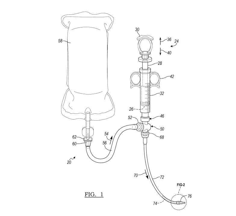
Fig. 1 is a plan view of an irrigation system, according to various
embodiments;
[0012]
Fig. 2 is a detailed end view of an irrigation nozzle, according to
various embodiments;
[0013] Fig. 3 is a schematic environmental view of an irrigation
site; and
[0014]
Fig. 4 is a plan view of an irrigation system, according to various
embodiments;
[0015]
Fig. 5 is a detailed view of an irrigation tip assembly, according to
various embodiments;
2
CA 03003638 2018-04-27
WO 2017/075058
PCT/US2016/058871
[0016]
Fig. 6 is a further detailed view of an irrigation tip assembly,
according to various embodiments; and
[0017] Fig. 7 is a plan view of an irrigation system, according to
various
embodiments.
[0018]
Corresponding reference numerals indicate corresponding parts
throughout the several views of the drawings.
DETAILED DESCRIPTION
[0019]
Example embodiments will now be described more fully with
reference to the accompanying drawings.
[0020]
With initial reference to Fig. 1, an irrigation system 20 is illustrated.
The irrigation system 20 is generally a manual irrigation system powered by a
user that holds a syringe assembly 24 in one or more hands to operate the
syringe assembly 24. The syringe assembly 24 may include a piston head 26
interconnected with a piston rod 28. The piston rod 28 may include various
features such as a thumb hole or loop 30 to assist in operation of the syringe
assembly 24 with one hand of a human user.
[0021] The syringe assembly 24 may be a manual pump that may include
various features such as further including finger or digit rings 42 to assist
in
manipulating the syringe assembly 24, in addition to the thumb hole or loop
30,
again with one hand of a human user. Further, a connection portion 46 may
include connection mechanisms such as a Luer-Loke syringe connection, twist
lock, press fit, or the like. Therefore, a mechanism may be interconnected
with
the syringe assembly 24 for use of the irrigation system20.
[0022] As is
generally understood by one skilled in the art, the syringe
assembly 24 may be operated to fill a syringe barrel 32 by moving the piston
head
26 with the piston rod 28 generally in the direction of arrow 36 and may be
emptied by moving the piston head 26 with the piston rod 28 generally in the
direction of arrow 40. It is understood, however, that the syringe assembly 24
may
also have a self-return or self-priming system. Self-return systems may
include a
spring (not illustrated) to bias the piston head 26 away from the connection
portion
46 generally in the direction of arrow 36. The user, to express the material
from
3
CA 03003638 2018-04-27
WO 2017/075058
PCT/US2016/058871
the syringe, would overcome the biasing force of the spring to express the
material and the biasing force would assist in moving or move the piston head
away from the connection portion 46 to refill the syringe barrel.
[0023]
Connected with the syringe assembly 24 at the connection portion
46 may be a valve assembly 50. The valve assembly 50 may include the dual
check valve 80187 sold by Qosina, having a place of business at Ronkonkoma,
NY. The valve assembly 50 may include various valve portions, including two
one-way valves. The two one-way valves may include a one-way valve assembly
52, which may be a first one-way valve assembly, that opens when negative
pressure is formed within the valve assembly 50. Negative pressure may be
produced when the piston head 26 moves generally in the direction of arrow 36
to
allow a flow of material through the one-way valve assembly 52 generally in
the
direction of arrow 54. The material may flow generally in the direction of
arrow 54
through a tubing 56. The tubing 56 may be a flexible tubing to connect with a
source container 58 holding or containing a volume or liquid, such as an
irrigant
liquid.
[0024]
The source container 58 may be a container, such as an IV bag or
other appropriate volume of an irrigation fluid. The irrigation fluid may be a
selected material such as saline. The irrigation fluid may further include
various
therapeutic reagents such as antibacterial, antimicrobial, anti-inflammatory,
analgesic, hemostatic, and wound healing components.
[0025]
The tubing 56 may be connected with a connector 60 to a
connection receptacle 62 of the irrigant volume container. The connector 60
and
the connection receptacle 62 can be any appropriate connection members, as is
generally understood in the art. The connection of the connector 60 with the
connection receptacle 62 may generally be an open connection such that fluid
will
generally flow from the source container 58 through the tubing 56 once the
connector 60 is connected with a connection receptacle 62. The one-way valve
assembly 52, however, may control flow of the fluid from the source container
58
to the syringe assembly 24, including within the syringe barrel 32.
[0026]
Accordingly, as noted above, when the piston head 26 generally
moves in the direction of arrow 36, the irrigant is drawn from the source
container
58 through the connection receptacle 62 and the connector 60 through the
tubing
4
CA 03003638 2018-04-27
WO 2017/075058
PCT/US2016/058871
56 and generally in the direction of arrow 54. The movement of the piston head
26 in the direction of arrow 36 may cause a negative pressure through the
connection portion 46 to the valve assembly 50 to open the one-way valve
assembly 52. Therefore, the syringe barrel 32 fills with the irrigant fluid.
[0027] Once a
selected volume of the irrigant is positioned within the
syringe barrel 32, however, movement of the piston head 26 in the direction of
arrow 36 may be ceased. The piston head 26 may then be moved in the direction
of arrow 40 to move the piston head 26 generally towards the connection
portion
46 to assist in removing or evacuating the irrigant material from the syringe
barrel
32.
[0028]
When the piston head 26 is moved generally in the direction of arrow
40, the pressure at the valve assembly 50 may be increased. The increased
pressure in the valve assembly 50 can close the one-way valve assembly 52 and
open a one-way valve assembly 68, which may be a second one-way valve
assembly. The increased pressure at the one-way valve assembly 68 may cause
the one-way valve assembly 68 to open to allow the irrigant to flow from the
syringe barrel 32 through the valve assembly 50 and generally in the direction
of
arrow 70 through a tubing 72. The tubing 72 may extend along a selected length
and may bend according to a selected configuration.
[0029] The tubing
72 may be formed of a material that may be rigid or
bendable. In various embodiments, the tubing 72 may be bent for use and may
maintain the selected bent configuration. Alternatively, or in addition
thereto, the
tubing 72 may only be flexible and a bendable support structure 74 may be
positioned at at least a region of the tubing 72 to assist in supporting and
holding
the tubing 72 in a selected shape. According to various embodiments, the
bendable support structure 74 may be a malleable tube, such as an aluminum
tube, fixed within the tubing 72. Various embodiments, may also include
malleable wires embedded in a wall of the tubing 72. Further, multiple tubes
may
be concentrically placed to support a bend. In still further various
embodiments, a
distal tube may be formed of a second material different from a proximal
portion of
the tubing 72 that may be malleable. It is understood, however, in various
embodiments the tubing 72 may be a single type flexible non-malleable tubing.
5
CA 03003638 2018-04-27
WO 2017/075058
PCT/US2016/058871
[0030]
The tubing 72 may be bent at a selected radius, such as near a tip
76 to assist in positioning the tip 76 at a selected location. For example,
the tip 76
may be selected to be positioned in a sinus cavity, as discussed further
herein,
and forming a radius or angle near the tip 76 may assist in positioning the
tip 76
within the selected sinus. The radius may be supported by the bendable support
structure 74 that may be different than the material of the tubing 72.
[0031]
With continued reference to Fig. 1 and additional reference to Fig. 2,
the tip 76 may be formed to cause a selected shape of a spray that exits the
tubing 72 and the tip 76. As illustrated in Fig. 2, a detailed view generally
along or
at the tip 76 of the tubing 72 is illustrated. The tip 76 may include a
selectively
shaped opening 80. The opening 80 may include a slit that has a first surface
82
and a second surface 84. The first and second surfaces 82, 84 may be angled
relative to one another and may include an elongated configuration such that a
fan-shaped spray emanates from the tip 76. The opening 80 may also include
sidewalls adjacent to the first and second surfaces 82, 84 to further direct
the
spray. The tip 76 may alternatively to the opening 80 and/or in additional to
the
opening 80 include one or more holes 85. The holes 85 may be selectively
shaped, such as circular, oval, discrete slits, etc.
[0032]
At the tip 76, the first surface 82 may be angled relative to the
second surface 84 to form a selected configuration of the spray, as noted
above,
which may be a fan shape. Further, due to the angle of the second surface 84,
the spray may be directional, such as spraying generally at the angle of the
second surface 84 and away from an axis 88 through the tip 76. This can allow
the tip 76 to be rotated around the axis 88, such as by rotating the syringe
assembly 24, to select a direction of the spray through the opening 80.
[0033] The tip 76, as discussed above may include one or more holes
85.
If a single one of the holes 85 is included the single hole may direct a
stream of
the fluid. The single hole may be positioned at any appropriate location
around or
along the tip 76. Alternatively, there may be many holes 85 positioned at
selected
locations on the tip 76. For example, the holes 85 may be formed as a ring
around an axis 88. The ring of holes may be partial or complete to spray in a
selected direction at the tip 76 relative to the axis 88.
6
CA 03003638 2018-04-27
WO 2017/075058
PCT/US2016/058871
[0034]
Visualization of the location and/or direction of the spray may be
made by direct endoscopic or direct visual inspection of the spray. Further, a
navigational marker, such as a radiopaque indicator 90 may be included to
indicate the location and/or direction of the spray from the opening 80. For
example, as illustrated in Fig. 2, a triangle or arrowhead may be the
radiopaque
indicator 90 that points towards the direction of the spray. Therefore, an
imaging
may be made to determine the location and/or direction of the spray from the
tip
76, such as through the opening 80 and/or the holes 85.
[0035]
Further, a cross-sectional area or volume of the opening 80 relative
to a cross-sectional area of an opening or lumen through the tubing 72 may be
selected at an appropriate ratio of about 1:1 to about 1:10,000, including
about 1:2
to about 1:100, including about 1:6. Further, more than one of the tips 76 may
be
provided on the tubing 72. Multiple tips may provide for a spray being
directed in
a plurality of directions at once. Further, the tips 76 may be selectable or
changeable during use. Different tips providing different rations may be used
to
provide different spray patterns and/or pressures. Accordingly, a kit may be
provided that includes the irrigation system 20 with one or more tips 76. The
tips
may be assembled during use. The kit may be provided in a container that
allows
sterilization of the kit prior to use. The ratio of the volume of the opening
80
relative to cross-sectional area of the lumen can allow for a selected
pressure to
be provided through the opening 80. Providing a selected pressure, such as a
pressure of about 1 pounds per square inch (PSI) to about 70 PSI may be
provided. The selected PSI may assist in a procedure, such as debridement of a
region. For example, debridement may include removing a biofilm, breaking an
agglomeration, or otherwise providing pressure to an area to assist in
removing
one or more selected materials (e.g. debris, bacteria, irritant or allergen),
or
clearing a selected area.
[0036]
With continuing reference to Figs. 1 and 2 and additional reference
to Fig. 3, the irrigation system 20 may be used to debride or irrigate a
selected
nasal passage or sinus cavity. As is generally understood by one skilled in
the
art, a subject, such as a human subject 100, may include or have a first nasal
passage 110 or a second nasal passage 112. Further, the human subject 100
may include one or more sinus cavities including schematically illustrated
sinus
7
CA 03003638 2018-04-27
WO 2017/075058
PCT/US2016/058871
cavities, including maxillary sinuses 114a and 114b and frontal sinuses 116a
and
116b.
[0037]
During a procedure, the tip 76 may be introduced through the first
nasal passage 110 and moved into the maxillary sinus 114a. The tip 76 may be
carried on the tubing 72 and may be manipulated into position via holding and
operating the syringe assembly 24. During use, the user may then move the
piston head 26 generally in the direction of arrow 36 to fill the syringe
barrel 32
and then generally in the direction of arrow 40 to express the irrigation
material
through the tubing 72 and out of the tip 76.
[0038] When
expressing the irrigation material out of the tubing 72 and tip
76, a spray 120 may be formed as the irrigation fluid impinges upon an
internal
surface of the maxillary sinus 114a. It is understood that the tip 76 may be
moved
through either or both of the first and second nasal passages 110, 112 into
any of
the selected sinus cavities, including either of the maxillary sinuses 114a or
114b,
or frontal sinuses 116a or 116b or other sinuses such as the sphenoid or
ethmoid
sinuses. Nevertheless, the user may operate the syringe assembly 24 to
irrigate
the sinus cavities and/or nasal passages.
[0039]
During operation, the user may continuously irrigate using a
reciprocating action of the piston head 26. By first moving the piston head 26
generally in the direction of arrow 36, the syringe barrel 32 may be filled
and then
expressing material by moving the piston head 26 generally in the direction of
arrow 40. As noted herein, the repeated movement of the piston head 26 in the
direction of the first arrow 36 then the second direction arrow 40 a
continuous
irrigation may be performed.
[0040] The
reciprocating motion of the piston head 26 may be manually
operated by the user and may not cause a continuously steady stream (e.g. the
continuous flow may be pulsatile) during the emptying of the source container
58.
However, due to the connection of the syringe assembly 24 to the source
container58 through the tubing 56 and the position of the valve assembly 50,
the
source container 58 may be emptied or continuously used until debridement or
irrigation is complete or the source container 58 is empty. Therefore, the
user
need not remove the syringe assembly 24 from the irrigation site to refill the
syringe assembly 24 during an irrigation procedure, but may maintain the tip
76 at
8
CA 03003638 2018-04-27
WO 2017/075058
PCT/US2016/058871
a selected irrigation position during an entire irrigation procedure while
manually
operating the syringe assembly 24 during the irrigation procedure.
[0041]
It is understood that the irrigation assembly, according to various
embodiments, as discussed herein, may be use to irrigate selected surfaces or
volumes. Fig. 3 is merely exemplary of irrigating a surface or cavity within a
human subject. It is understood, however, that other cavity within a subject
may
be irrigated. Further, devices, such as implants or treatment devices may have
the irrigant applied to their surfaces before, during, or after positioning
with in a
subject. For example, an implant may have its surface irrigated after
implantation
to assist in removing an infection, etc.
[0042]
An irrigation system 220, according to various embodiments, is
illustrated in Fig 4, Fig. 5, and Fig. 6. The irrigation system 220 is a
manual
irrigation system that is configured to be powered by a user. For example, a
user
may apply manual pressure to operate the irrigation system 220. Further, the
irrigation system 220 may include components similar to the irrigation system
20,
discussed above. Identical components to the irrigation system 20 will be
given
the same reference numeral in the irrigation system 220 and not discussed in
detail below.
[0043]
The irrigation system 220 may include a syringe system or assembly
224. The syringe assembly 224 may be operated by one or more hands of a user
as a manual pump to express or spray an irrigant from the syringe assembly
224.
The irrigant may be the same as that discussed above, and may be sprayed into
various portions of the human subject 100, as discussed above and illustrated
in
Fig. 3. It is understood, however, that the irrigation system 220 may be used
to
irrigate any selected volume and the irrigation of a human patient is not
required.
[0044]
The syringe assembly 224 may be similar to the BD CornwallTM
disposable syringe system, sold by Becton, Dickinson & Co., having a place of
business in Franklin Lakes, NJ, USA. The syringe assembly 224 may include a
syringe barrel 226 and a syringe plunger 228. As discussed herein, the syringe
barrel 226 may operate as a pump barrel having a volume and the syringe
plunger
228 may be a plunger for a pump. Connecting the syringe barrel 226 and the
syringe plunger 228 may be a spring member 232. The spring member 232 may
be held within a casing or handle 234. The spring member 232 may be any
9
CA 03003638 2018-04-27
WO 2017/075058
PCT/US2016/058871
appropriate biasing member or system to apply a bias force to the handle 234
and/or the syringe plunger 228.
[0045]
The spring member 232 may be formed of a selected material, such
as a metal or metal alloy, that causes it to be biased to an expanding or open
position. Thus, the spring member 232 may be a biasing member that biases the
handle 234 and/or the syringe plunger 228. In biasing the syringe plunger 228,
the spring member 232 may bias and/or draw the syringe plunger 228 generally
in
the direction of arrow 236 to move a plunger head 238 in a first direction in
the
syringe barrel 226. By moving the syringe plunger 228 in the direction of
arrow
236, a pressure in the syringe barrel 226 may be reduced so that it may be
filled
with a fluid from the source container58. The spring member 232, therefore,
biases the syringe assembly 224 to assist in filling the syringe barrel 226
and
generally towards a full position. The handle 234 may further include a
stopping
or an arresting strap 240 that connects to a stop member or portion 242. The
stop
member or portion 242 is configured to engage a fixed portion of the syringe
barrel 226 or is fixed to the syringe barrel 226. The arresting strap 240
engages
the stop member or portion 242 to limit travel of the handle 234 when biased
by
the spring member 232.
[0046]
The irrigant may be manually expressed from the syringe assembly
224 by the user grasping the handle 234 and squeezing or pressing a first
handle
member 234a towards the syringe barrel 226 and towards a second handle
member 234b generally in the direction of arrow 250, which may be opposite the
direction of the arrow 236. In squeezing the handle 234, the user moves the
syringe plunger 228 in a second direction in the syringe barrel 226, and
generally
in the direction of arrow 250. This forces a fluid out of the syringe barrel
226 and
through the valve assembly 50, connected to the syringe barrel 226. The
expressed material is directed, by the valve assembly 50, through the tubing
72.
[0047]
Once a selected material has been expressed or emptied from the
syringe barrel 226, the user may release or stop squeezing the handle 234.
Once
the handle 234 is released, the spring member 232 in applying the biasing
force,
will cause the handle 234, connected to the syringe plunger 228, to generally
move in the direction of arrow 236. The spring member 232 may be configured
and manufactured to overcome any force applied by the first handle member and
CA 03003638 2018-04-27
WO 2017/075058
PCT/US2016/058871
the second handle member 234a, 234b, alone, and friction of the syringe
plunger
228 within the syringe barrel 226. In this manner, the syringe barrel 226 may
be
refilled with an irrigant from the source container 58 as the spring member
232
biases the handle 234 in the direction of arrow 236 to move the syringe
plunger
228 in the direction of arrow 236. The spring member 232, therefore, may also
make continuous or extended irrigation easier and less stressful to a user.
The
biasing spring may provide all of the force necessary to refill the syringe
barrel
226. Thus, the user may only need to provide the force to express material
from
the irrigation system220. As noted herein, expressing material may be
performed
by the user squeezing the handle 234.
[0048]
The source container or source container 58 may be connected with
the syringe barrel 226 via or with tubing, such as flexible tubing 56. The
source
container 58 may hold any selected irrigation fluid, such as those discussed
above
including sterile saline or other materials that may include therapeutic
agents such
as antimicrobials, antibacterials, or the like. Further, the source container
58 may
be any appropriate container, such as an IV bag.
[0049]
The source container 58 may be connected with the tubing 56 using
the connector 60 at the connection receptacle 62 with the source container 58.
The tubing 56 and connector 60 and connection receptacle 62 may be
substantially similar to that discussed above. Further, as material exits the
source
container 58 it may flow in through the tubing generally in the direction of
the
arrow 54 through the valve assembly 50. The valve assembly 50 may be similar
or identical to the valve assembly discussed above including the check valve
80187 sold by Qosina. The valve assembly 50 may include two one-way valves,
as discussed above. Accordingly, the valve assembly 50 may allow material only
to flow from the source container 58 into the syringe barrel 226 and not from
the
syringe barrel 226 into the source container 58. Further, the valve assembly
50
may allow material to be expressed only from the syringe barrel 226 through
the
irrigation tubing 72 while not allowing material to move through the valve
assembly 50 from the irrigation tubing 72 either into the syringe barrel 226
or into
the source container tubing 56. Therefore, the valve assembly 50 allows
material
to be drawn from the source container 58 into the syringe barrel 226 and then
expressed and irrigated through the irrigation tubing 72 generally in the
direction
11
CA 03003638 2018-04-27
WO 2017/075058
PCT/US2016/058871
of arrow 70. The valve assembly 50, however, will generally not allow flow in
the
directions opposite of arrows 54 and 70.
[0050]
The valve assembly 50 allows the irrigation system220 to be used to
draw an irrigation material from the source container 58 into the syringe
barrel 226
and then express the irrigation material from the syringe barrel 226 through
the
tubing 72, in a manner similar to that discussed above. The irrigation
system220
may be operated by the user squeezing the handle 234 to empty the syringe
barrel 226 (at least a selected amount). The spring member 232 may then bias
the syringe plunger 228 out of the syringe barrel 226 generally in direction
of
arrow 236 to refill the syringe barrel 226 from the source container 58. This
operation allows for substantially continuous irrigation by reciprocating the
syringe
plunger 228 in the syringe barrel 226. The user squeezes the handle 234 to
express material and then releases the handle 234 to allow the spring member
232 to move the syringe plunger 228 to refill the syringe barrel 226 for the
user to
then express more fluid, if selected.
[0051]
The tubing 72 may be connected to a terminal irrigation assembly or
tip assembly 300. The terminal irrigation assembly 300, as illustrated in Fig.
4,
Fig. 5, and Fig. 6, may include a vacuum tube connection region 302 that may
include a connection member 304 having a proximal male connector 306 and a
distal male connector 308. The proximal male connector 306 may be received
within a female connector 309 of a vacuum source tube 311. The distal male
connector 308 may be received within a proximal connection portion 312 of an
irrigation tip holder 320. It is understood, however, that the irrigation tip
holder
320 need not be included as a separate or separable member.
[0052] The vacuum source tube 311 may be connected to a vacuum source
321. The vacuum source may be any appropriate source, such as a PM61 Power
Vac Aspirator, sold by Precision Medical, Inc., having a place of business in
Northampton, PA. The vacuum source may also be a non-portable system such
as a constant suction system, such as one generally available in hospitals as
a
central suction system.
[0053]
If selected, the irrigation tip holder 320 may include an external wall
322 that defines an internal cannula 324. The suction may be drawn through the
internal cannula 324 and the suction or vacuum source tube 311. The irrigation
12
CA 03003638 2018-04-27
WO 2017/075058
PCT/US2016/058871
tip holder 320 may be formed from a syringe barrel such as a syringe Luer-Loke
hypodermic syringe sold by Becton, Dickinson and Company Corporation, having
a place of business in Franklin Lakes, NJ. The syringe barrel may have the
vacuum tube connection region 302 positioned within a proximal end 326 of the
syringe barrel that defines the proximal connection portion 312. As discussed
herein, therefore, suction may be drawn through the irrigation tip holder 320
at a
selected time. The irrigation tip holder 320 may further include a Luer-loke
hypodermic syringe with a partial or half-twist connection at a distal end
connector
330. A Y-connector or Y-connection portion 340 may connect with the distal end
connector 330. As noted above, the irrigation tip holder 320 need not be
included
and the vacuum source tube 311 may be connected directly to the Y-connector
340.
[0054] The Y-connector 340, as discussed further herein, may
communicate with or have an irrigation tip tube 350 passed through at least a
portion of the Y-connector 340, including an "Y"-arm or extension 354
extending
from a central member 356 of the Y-connector 340. The central member 356 may
define a first, main, or central cannula 358 and the Y-arm or extension 354
may
also define a secondõ auxiliary, or extension cannula 360. The central cannula
358 may intersect with the extension cannula 360 and be in fluid
communication.
The Y-connector 340 may be connected at the distal end connector 330 to the
irrigation tip holder 320. As discussed herein, suction may draw material
through
the central cannula 358 and the internal cannula 324 through the vacuum source
tube 311.
[0055]
The Y-connector 340 connects at a connection region 352 with one
or more sheaths that are sheather so the sip tube 350. The tip tube 350 may be
sheathed or covered in one or more fixed shape sheaths or sleeves. The sheaths
may include a 70 curved sheath 370, a 120 curved sheath 372, and a 13
curved sheath 374. It is understood, however, that more sheaths may be
provided and that sheaths of other curvatures may be provided. Each of the
sheaths 370, 372, 374 may be passed over the tip tube 350. The tip tube 350
may be flexible enough that it will obtain or be held in the shape of the
sheath 370,
372, 374 when placed inside of the sheath 370, 372, 374. Each of the sheaths
370, 372, 374 may be selectively and/or separately connected to the connection
13
CA 03003638 2018-04-27
WO 2017/075058
PCT/US2016/058871
region 352. Each of the sheaths may include an outer diameter of about 1
millimeter (mm) to about 10 mm, including about 1 mm to about 6 mm, and
further
including about 3 mm to about 5 mm.
[0056] The tip 76 may extend from the tip tube 350.
In various
embodiments, the tip 76 may be formed separate from the tip tube 350 and
inserted into and connected to the tip tube 350. In various embodiments, the
tip
76 may be formed at a distal end of the tip tube 350. The tip tube 350 extends
from the tip 76 through a portion of the Y-connector 340 at the connection
region
352 and into the extension cannula 360 of the Y-arm or extension 354. The tip
tube 350 further extends through an extension arm connector 380 and a
directional control system that may include a direction control member (e.g. a
grip
or handle) 382 to a tip tube connector 400. The tip tube connector 400 may
connect with a female connector 310 of the tubing 72. When connected, as
material is expressed from the syringe barrel 226, the material may travel
past the
valve assembly 50 (in the general direction of arrow 70) through the tubing 72
and
through the tip tube 350 and the tip 76 to a selected location, such as within
a
sinus passage as discussed above. Therefore, material may be irrigated through
the tip 76 of the irrigation tip tube 350 from the syringe barrel 226.
[0057]
The tip tube 350 may be fixedly connected to the direction control
member 382 which may rotate within the extension arm connector 380. As the
direction control member 382 rotates, such as around an axis 410 in the
direction
of double headed arrow 412, the tip tube 350 may also rotate causing the tip
76 to
also rotate. As the tip 76 rotates it may be rotated around an axis 420 that
may be
defined by the tip tube 350 and the selected sheath positioned over the tip
tube
350, such as the sheath 370 as illustrated in Figs. 5 and 6.
[0058]
As discussed above, the tip 76 may include the opening 80 that
forms a fan or other selected shape of the spray of the material being
expressed
through the tip or from the tip 76. In rotating the direction control member
382
around the axis 410, which in turn rotates the tip 76 around the axis 420,
generally
in direction of the double headed arrow 424, allows the fan or other shaped
spray
to also be rotated around the axis 420. Therefore, if a substantially flat fan
is
expressed from the tip 76 and the fan rotates around the axis 420, the fan may
cover a surface generally defining a circle or disc shape around the axis 420.
14
CA 03003638 2018-04-27
WO 2017/075058
PCT/US2016/058871
[0059]
Further, the sheath 370 (as may all of the sheaths 370, 372, 374)
may include an opening or passage between an internal wall 430 and an outer
wall 434 of the tip tube 350. The sheath 370, in forming the passage, will
allow
the suction or vacuum formed from the vacuum source 321 to be drawn through
the sheath 370 and, in turn, through the central cannula 358 of the Y-
connector
340 and the internal cannula 324 of the irrigation tip holder 320 and then
through
the vacuum source tube 311. The suction may be passed the tip 76 and though
the selected sheath 370, 372, 374, generally in the direction of arrow 450.
[0060] As discussed above, the vacuum source 321 may be a constant
vacuum source providing a constant vacuum and suction through the terminal
irrigation assembly 300. Thus, suction may always be provided at or near the
tip
76 through the sheath, such as the sheath 370, even during expressing or
irrigation of a selected area. In providing constant suction or vacuum, the
irrigation material may not build up at a selected location and removed or
debrided
material may be withdrawn once it is loosened from a selected surface.
Therefore, the terminal irrigation assembly 300 may provide both a suction and
irrigation at or near the tip 76 of the terminal irrigation assembly 300.
[0061]
Accordingly, the irrigation system 220 may be operated to irrigate at
the tip 76 and vacuum or suction material near the tip 76 through the sheath
370
(or other appropriate sheath 370, 372, 374) connected to the connection region
352. A user may irrigate an area, such sinus or other selected volume, and
material once expressed from the tip 76 and/or debrided from a surface may be
removed with the suction.
[0062]
It is understood that the irrigation system 220 may be operated in
performing a procedure on a human, such as for irrigation of the nasal passage
or
sinus cavity. It is further understood, however, that irrigation system 220
may be
used in a non-human subject for irrigating, providing a selected material
(e.g., a
lubricant) or cleaning a selected volume of any appropriate object. For
example,
the irrigation system 220 may be used to provide a selected liquid to a
machine
system for a selected purpose, including those expressed above.
[0063]
In addition, the user may remove the syringe assembly 224 from the
Y-connector 340 and place a cap or other member 391 in its place. The cap 391
may be tethered to the Y-connector 340 or otherwise obtained to block the
CA 03003638 2018-04-27
WO 2017/075058
PCT/US2016/058871
irrigation passage of the Y-connector 340. When blocked, the vacuum source 321
would provide the only flow through the Y-connector 340 and the system may
operate in a suction only mode. Thus, the irrigation system 220 may be blocked
to allow only suction, for various purposes.
[0064] According
to various embodiments an irrigation system 220', as
illustrated in Fig. 7, may be altered relative to the irrigation system 220
illustrated
in Fig. 4 above. The irrigation system220' illustrated in Fig. 7 may include
the
syringe assembly 224 connected to the Y-connector 340 without the tubing 72
between the syringe assembly 224 and the Y-connector 340. The syringe
assembly 224 may be connected to the Y-connector 340 through the female
connector 310 and the direction control member 382. Therefore, the direction
control member 382 may be still operated to change direction of the tip 76 by
moving the tip tube connector 400, as discussed above.
[0065]
Further, as illustrated in Fig. 7, the irrigation system 220' may have
the syringe assembly 224 connected to the central member 356 rather than to
the
Y-arm or extension 354 as illustrated in Figs. 4, 5, and 6. It is understood
that this
is not required, but that the Y-connector 340 may be connected in either
manner
for the irrigation system 220, illustrated in Fig. 4, or the irrigation system
220',
illustrated in Fig 7. In the irrigation system 220', however, the cannula 358
through the central member 356 is not operated as the suction cannula, but is
the
irrigation cannula. Further, the extension cannula 360 in the Y-arm or
extension
354 is not the irrigation cannula, but is the suction cannula. Therefore, the
cannula in either the central member 356 or the Y-arm or extension 354 is
determined by which portion to which it is connected.
[0066] In this
manner, the irrigation system220' may be operated with a
substantially single hand (ass illustrated in Fig. 7) of the user or operator
without
requiring the user to hold the syringe assembly 224 in one hand and the
terminal
irrigation assembly 300 in a separate hand. The user, therefore, may be able
to
move the tip 76 with the sheath 370 by moving the syringe assembly 224 rigidly
connected to the sheath 370 through the Y-connector 340. The user may further
be able to operate or rotate the tip tube connector 400 with the direction
control
member 382, as discussed above. Nevertheless, the syringe assembly 224 may
be rigidly connected to the terminal irrigation assembly 300 to assist in
efficiently
16
CA 03003638 2018-04-27
WO 2017/075058
PCT/US2016/058871
operating the irrigation system220' without the need for the separate tubing
72.
The irrigation system220', however, may operate substantially similar to the
irrigation system 220 as described above without the tubing 72. That is, upon
squeezing the handle 234, the syringe plunger 228 may move in the direction of
arrow 250 to move the irrigation fluid generally in direction of arrow 70
through the
terminal irrigation assembly 300 and the tip 76 to irrigate a selected
location.
[0067]
Example embodiments are provided so that this disclosure will be
thorough, and will fully convey the scope to those who are skilled in the art.
Numerous specific details are set forth such as examples of specific
components,
devices, and methods, to provide a thorough understanding of embodiments of
the present disclosure. It will be apparent to those skilled in the art that
specific
details need not be employed, that example embodiments may be embodied in
many different forms and that neither should be construed to limit the scope
of the
disclosure. In some example embodiments, well-known processes, well-known
device structures, and well-known technologies are not described in detail.
[0068]
The foregoing description of the embodiments has been provided for
purposes of illustration and description. It is not intended to be exhaustive
or to
limit the disclosure. Individual elements or features of a particular
embodiment are
generally not limited to that particular embodiment, but, where applicable,
are
interchangeable and can be used in a selected embodiment, even if not
specifically shown or described. The same may also be varied in many ways.
Such variations are not to be regarded as a departure from the disclosure, and
all
such modifications are intended to be included within the scope of the
disclosure.
17