Note: Descriptions are shown in the official language in which they were submitted.
STORAGE BIN WITH LUGGAGE POSITIONING PROTRUSIONS
CROSS REFERENCE TO RELATED APPLICATIONS
[0001] This application claims the benefit of U.S. Provisional Application
No. 62/264,205, filed
December 7, 2015
FIELD OF THE INVENTION
[0002] The present invention relates generally to overhead storage bin
assemblies, and more
particularly to an assembly in an overhead storage bin assembly that helps
position luggage within
the bin.
BACKGROUND OF THE INVENTION
[0003] Commercial aircraft, such as the Airbus A320 or Boeing 737 are
typically constructed
from modular components, the size, weight and construction of which are
dictated by many
considerations, including fuselage dimensions, aesthetic and safety
considerations. Many of these
requirements are imposed by law or regulation. Aircraft components, such as
overhead stowage
compartments, seats, lavatories, galleys, lighting systems, etc. are all
required to function within
strictly confined spaces.
[0004] Manufacturers of aircraft are constantly refining interior aircraft
designs to achieve more
comfort and utility for passengers and crew within carrier-imposed restraints
on cost, weight,
maintenance down-time, and safety. Commercial passenger aircraft generally
include overhead
luggage storage bins mounted from the ceiling, walls or other structural
portion of the aircraft
over the passenger seats. These bins are designed to accommodate the size,
shape, and weight of
passenger carry-on luggage. Positioning of the luggage within the bin is
important in order to
maximize the volume within the bin that is used and to reduce hand loads
required for closing the
bin.
1
CA 3003753 2019-05-17
[0005] Other overhead storage bin assemblies are well known in the art. For
example, see U.S.
Patent Publication No. 2011/0253837 published October 20, 2011, U.S. Patent
No. 4,637,642
issued on January 20, 1987, U.S. Patent No. 5,567,028 issued on October 22,
1996, and U.S.
Patent No. 8,262.022 issued on September 11,2012.
BRIEF DESCRIPTION OF THE DRAWINGS
[0006] FIG. 1 is a cross-sectional side elevation of an aircraft storage
bin in accordance with a
preferred embodiment of the present invention;
[0007] FIG. 2 is an exploded perspective view of the interior of the bucket
of the aircraft storage
bin of FIG. 1 ;
[0008] FIG. 3 is an exploded perspective view of the exterior of the bucket
of the aircraft storage
bin of FIG. 1 ;
[0009] FIG. 4A is a cross-sectional side elevation of an aircraft storage
bin in the open position
and with a piece of luggage in the first position;
[0010] FIG. 4B is a cross-sectional side elevation of an aircraft storage
bin in the closed position
and with a piece of luggage in the first position;
[0011] FIG. 5 A is a cross-sectional side elevation of an aircraft storage
bin in the open position
and with a piece of luggage in the second position; and
[0012] FIG. 5 A is a cross-sectional side elevation of an aircraft storage
bin in the open position
and with a piece of luggage in the second position; and
[0013] Like numerals refer to like parts throughout the several views of
the drawings.
SUMMARY OF THE PREFERRED EMBODIMENTS
[0014] In accordance with a first aspect of the present invention there is
provided an aircraft
storage bin that includes an upper housing, and a bucket movable with respect
to the upper
2
CA 3003753 2019-05-17
CA 03003753 2018-04-30
WO 2017/099977
PCT/US2016/062890
housing between a closed position and an open position. The upper housing and
the bucket
cooperate to define a bin interior. The bucket includes a bottom and first and
second
opposing side walls. The bottom of the bucket includes an outer surface, an
inner surface, a
front edge, and first and second protrusions protruding into the bin interior.
The first
protrusion defines a first luggage engaging surface and the second protrusion
defines a
second luggage engaging surface. In a preferred embodiment, the first and
second
protrusions extend between the first and second side walls and at least one of
the first and
second protrusions is formed in the bottom. In another embodiment, the first
protrusion is
formed in the bottom and wherein the second protrusion is secured to the
bottom.
[0015] Preferably, the outer surface of the first protrusion defines a
channel that includes at
least a portion of a latch button assembly disposed therein. In a preferred
embodiment, first
and second cables extend outwardly from the latch button assembly and through
the
channel and the channel includes a cover. Preferably, the channel includes a
button
opening defined therethrough and the first protrusion includes a latch opening
defined
therethrough.
[0016] In a preferred embodiment, a first luggage zone is defined between
the first luggage
engaging surface and the back and a second luggage zone is defined between the
second
luggage engaging surface and the back. Preferably, the second protrusion
includes a
platform portion.
[0017] In accordance with another aspect of the present invention there is
provided an
aircraft storage bin that includes an upper housing, and a bucket movable with
respect to
the upper housing between a closed position and an open position. The upper
housing and
the bucket cooperate to define a bin interior. The bucket includes a bottom
and first and
second opposing side walls. The bottom includes an outer surface, an inner
surface, a front
edge, and first and second protrusions extending between the first and second
side walls
3
CA 03003753 2018-04-30
WO 2017/099977
PCT/US2016/062890
and protruding into the bin interior. The first protrusion defines a first
luggage engaging
surface and the second protrusion defines a second luggage engaging surface. A
first
luggage zone is defined between the first luggage engaging surface and the
back and a
second luggage zone is defined between the second luggage engaging surface and
the back.
At least the first protrusion is formed in the bottom and an outer surface of
the first
protrusion defines a channel that includes at least a portion of a latch
button assembly
disposed therein. First and second cables extend outwardly from the latch
button assembly
and through the channel. The channel includes a cover that has a button
opening defined
therethrough and the first protrusion includes a latch opening defined
therethrough.
DETAILED DESCRIPTION OF THE PREFERRED EMBODIMENTS
[0018] The following description and drawings are illustrative and are not
to be construed as
limiting. Numerous specific details are described to provide a thorough
understanding of
the disclosure. However, in certain instances, well-known or conventional
details are not
described in order to avoid obscuring the description. References to one or an
embodiment
in the present disclosure can be, but not necessarily are references to the
same
embodiment; and, such references mean at least one of the embodiments.
[00191 Reference in this specification to "one embodiment" or "an
embodiment" means that
a particular feature, structure, or characteristic described in connection
with the
embodiment is included in at least one embodiment of the-disclosure. The
appearances of
the phrase "in one embodiment" in various places in the specification are not
necessarily
all referring to the same embodiment, nor are separate or alternative
embodiments
mutually exclusive of other embodiments. Moreover, various features are
described which
may be exhibited by some embodiments and not by others. Similarly, various
requirements
are described which may be requirements for some embodiments but not other
embodiments.
4
CA 03003753 2018-04-30
WO 2017/099977
PCT/US2016/062890
[0020] The terms used in this specification generally have their ordinary
meanings in the art,
within the context of the disclosure, and in the specific context where each
term is used.
Certain terms that are used to describe the disclosure are discussed below, or
elsewhere in
the specification, to provide additional guidance to the practitioner
regarding the
description of the disclosure. For convenience, certain terms may be
highlighted, for
example using italics and/or quotation marks: The use of highlighting has no
influence on
the scope and meaning of a term; the scope and meaning of a term is the same,
in the same
context, whether or not it is highlighted.
[0021] It will be appreciated that the same thing can be said in more than
one way.
Consequently, alternative language and synonyms may be used for any one or
more of the
terms discussed herein. No special significance is to be placed upon whether
or not a term
is elaborated or discussed herein. Synonyms for certain terms are provided. A
recital of one
or more synonyms does not exclude the use of other synonyms. The use of
examples
anywhere in this specification including examples of any terms discussed
herein is
illustrative only, and is not intended to further limit the scope and meaning
of the
disclosure or of any exemplified term. Likewise, the disclosure is not limited
to various
embodiments given in this specification.
[0022] Without intent to further limit the scope of the disclosure,
examples of instruments,
apparatus, methods and their related results according to the embodiments of
the present
disclosure are given below. Note that titles or subtitles may be used in the
examples for
convenience of a reader, which in no way should limit the scope of the
disclosure. Unless
otherwise defined, all technical and scientific terms used herein have the
same meaning as
commonly understood by one of ordinary skill in the art to which this
disclosure pertains.
In the case of conflict, the present document, including definitions, will
control.
[0023] It will be appreciated that terms such as "front, ' ''back," "top,"
"bottom," "side," "short,"
"long, ""up," "down," "aft." "forward," "inboard," "outboard" and "below" used
herein are merely
for ease of description and refer to the orientation of the components as
shown in the figures. It
should be understood that any orientation of the components described herein
is within the scope
of the present invention.
[0024] Referring now to the drawings, wherein the showings are for purposes
of illustrating the
present invention and not for purposes of limiting the same, FIGS. 1 -16 show
a pivot bin
assembly 10. In particular, the invention can be used on commercial passenger
aircraft. However,
this is not a limitation on the present invention and the pivot bin assembly
can be used elsewhere.
[0025] The present invention is directed to an aircraft storage bin 10 that
includes an upper
housing 12 and a bucket 14 that is movable with respect to the upper housing
12. The bucket 14
may pivot, translate or otherwise move in any way with respect to the upper
housing 12 between a
closed position and an open position so that luggage 100 or other items can be
positioned in the
bin interior 16 that is defined by the bucket 14 and the upper housing 12. The
present invention
aircraft storage bin 10 employs a "clamshell design," such as the one
disclosed in U. S. Patent No.
8,955,805. In the "clam shell" configuration the side walls of the bucket 14
abut the side walls of
the upper housing. However, it will be appreciated by those of ordinary skill
in the art that the
bucket can have the shape of any bucket used in aircraft storage bins. For
example, the bucket can
have a C-shaped cross section with a top and sides that do not about the upper
housing, similar to
that taught in U. S. Patent Publication No. 2011/0139929. Furthermore, in a
preferred
embodiment, the storage bin 10 is used in a
6
CA 3003753 2019-05-17
CA 03003753 2018-04-30
WO 2017/099977
PCT/US2016/062890
passenger aircraft. However, this is not a limitation on the present invention
and the bin
can be used for storage in other places and situations.
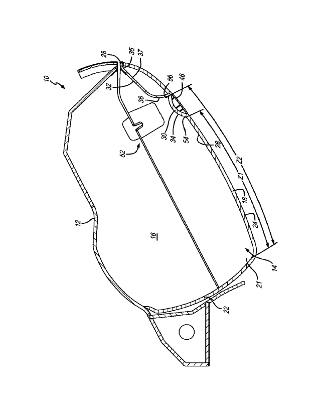
[0026[ As shown in FIGS. 1-5B, the bucket 14 generally includes a bottom
18, first and
second opposing sides 20 and 21 secured to and extending upwardly from the
bottom 18,
and a back 22. The bottom 18, first and second sides 20 and 21 and back 22 can
be a single
unitary piece or can be separate pieces secured or affixed together. The
bottom 18 includes
an outer surface 24, an inner surface 26, a front edge 28, and first and
second protrusions
30 and 32 protruding into the bin interior 16. As shown in FIG. 1, the first
protrusion 30
defines a first luggage engaging surface 34 and the second protrusion 32
defines a second
luggage engaging surface 36. In a preferred embodiment, the first and second
protrusions
30 and 32 extend or span the entire distance of the interior of the bucket
from the first side
wall 20 to the second side wall 21 (see FIG. 2). In another embodiment, the
first and
second protrusions 30 and 32 can extend part of the distance between the sides
or can by
broken up by indentations or openings. As shown in FIG. 1, in a preferred
embodiment, the
second protrusion 32 includes a front edge portion 35 that is generally flush
with the front
edge 28 of the bucket 14 and a platform portion 37 extending between the front
edge
portion 25 and the first luggage engaging surface 34. Luggage that is
different sized or
does not readily fit into the luggage zones described below can rest on the
platform portion
37. In a preferred embodiment, the second protrusion 32 is thick enough that
it provides
lateral support and strength to the bucket 14 and prevents the side walls and
bottom from
flexing side to side (aft to forward). This also helps prevent the bucket from
flexing during
flight and causing the latch to unhook.
[0027] As shown in FIG. 2, in a preferred embodiment, the first protrusion
30 is formed in
or is a part of the bottom 18 of the bucket 14 and the second protrusion 32 is
a separate
piece or component that is secured to or otherwise attached to the inner
surface 26 of the
7
bottom 18. In another embodiment, both of the first and second protrusions 30
and 32 can be
secured to the bottom 18. In a preferred embodiment, the first protrusion 30
includes a latch
opening 38 defined therethrough that is covered by a latch cover 40. The latch
cover and opening
38 provide access to a latch button assembly 42.
[0028] As shown in FIG. 3, in a preferred embodiment, the outer surface 30a
of the first
protrusion defines a channel 44 that at least partially receives or houses the
latch button assembly
42. The bucket 14 also includes a cover strip 46 that covers the latch button
assembly 42 on the
outside thereof. and includes a button opening 48 through which the button 50
of the latch button
assembly 42 extends or is accessible. The cover strip 46 partially defines the
channel 44 together
with the outer surface 30a of the first protrusion 30. In a preferred
embodiment, cables 53 extend
from the latch button assembly 42 through the channel 44 and to the latch
assemblies 52 located
in or on the sidewalls 20 and 21, It will be appreciated that the type of
latch button assembly and
button is not a limitation on the present invention. The button can be pushed
inwardly or pulled
outwardly to activate the latches. In the figures, the latches that secure the
bucket 14 to the upper
housing 12 are located in the sidewalls of the bucket 14 and the upper housing
12. However, in
another embodiment, the latch can be positioned such that it connects the
front edge of the bucket
to the front edge of the upper housing. In a preferred embodiment, the latch
system used with
storage bin 10 is the latch system taught in U. S. Patent No. 9,731,827 titled
Overhead Storage
Bin Latch System. However, this is not a limitation and other latch systems
can be used.
[0029] As shown in FIGS. 4A-5B, one of the advantages of the first and
second protrusions 30
and 32 is to position luggage 100 closer to the back 22 of the bucket 14 or
more
8
CA 3003753 2019-05-17
CA 03003753 2018-04-30
WO 2017/099977
PCT/US2016/062890
outboard (assuming a narrow body aircraft) than if the protrusions were not
present (or
further away from the front edge than if the protrusions were not present).
Positioning
luggage outboard (and away from the front edge of the bucket) moves the center
of gravity
of the luggage outboard and closer to the pivot point, thereby making it
easier to close the
bin or move the bucket 14 from the closed position to the open position. In
other words, a
bucket that includes the first and second protrusions requires lower hand
loads to close
than a bucket without the protrusions. Furthermore, by having two protrusions,
different
sized luggage can be positioned further outboard, as described below.
[0030] FIGS. 4A-4B show the bin 10 with a smaller piece of luggage 100
therein. As shown
in FIG. 4A, when the luggage 100 is placed in the bucket 14 the bottom inboard
corner 102
engages or rests against the first luggage engaging surface 34. It will be
appreciated that
the first luggage engaging surface 34 cooperates with the inner surface 26 of
the bottom 18
to form a first notch 54 that receives the bottom inboard corner 102 of
luggage 100.
Furthermore, a first luggage zone Z1 is defined between the first notch 54 or
the first
luggage engaging surface 34 and the back 22. As shown in FIG. 4B, when the
bucket 14 is
moved to the closed position, the luggage 100 stays within the first luggage
zone Zl. When
the bucket 14 is moved back to the open position, the first protrusion 30
(and, more
particularly, the first luggage engaging surface 34) maintains the luggage 100
in the first
luggage zone Z1, as shown in FIG. 4A.
[0031] FIGS. 5A-5B show the bin 10 with a larger piece of luggage 100
therein (i.e., a piece
of luggage that is too long to fit in the first luggage zone Z1). As shown in
FIG. 5A, when
the luggage 100 is placed in the bucket 14 the bottom inboard comer 102
engages or rests
against the second luggage engaging surface 36. It will be appreciated that
the second
luggage engaging surface 36 cooperates with the inner surface of the first
protrusion 30 to
form a second notch 56 that receives the bottom inboard comer 102 of luggage
100.
9
CA 03003753 2018-04-30
WO 2017/099977
PCT/US2016/062890
Furthermore, a second luggage zone Z2 is defined between the second notch 56
or the
second luggage engaging surface 36 and the back 22. As shown in FIG. 5B, when
the
bucket 14 is moved to the closed position, the luggage 100 stays within the
second luggage
zone Z2. When the bucket 14 is moved back to the open position, the second
protrusion 32
(and, more particularly, the second luggage engaging surface 36) maintains the
luggage
100 in the second luggage zone Z2, as shown in FIG. 5A.
[0032] It will be appreciated by those of ordinary skill in the art that
luggage smaller than a
first predetermined length or dimension (the distance or length between the
first luggage
engaging surface 34 and the back 22) fits in or is positioned in the first
luggage zone, and
luggage that is longer than the first predetermined length fits in or is
positioned in the
second luggage zone. Luggage that is longer than the distance between the
second luggage
engaging surface 36 and the back 22 rests on the platform portion 37 (referred
to herein as
the third luggage zone). Accordingly, the present invention also includes a
method of
positioning luggage in the bin interior. The method includes positioning a
first sized piece
of luggage in the first luggage zone and positioning a second sized luggage
that is longer
than the first sized luggage in the second luggage zone. Put differently, the
method
includes positioning the first sized luggage between the back and the first
luggage
engaging surface and positioning the second sized luggage between the back and
the
second luggage engaging surface (but where the lower inboard corner extends
beyond the
first luggage engaging surface).
[0033] Unless the context clearly requires otherwise, throughout the
description and the
claims, the words "comprise," "comprising," and the like are to be construed
in an
inclusive sense, as opposed to an exclusive or exhaustive sense; that is to
say, in the sense
of "including, but not limited to." As used herein, the terms "connected,"
"coupled," or any
variant thereof, means any connection or coupling, either direct or indirect,
between two or
more elements; the coupling of connection between the elements can be
physical, logical, or a
combination thereof. Additionally, the words "herein," "above," "below," and
words of similar
import. when used in this application, shall refer to this application as a
whole and not to any
particular portions of this application. Where the context permits, words in
the above Detailed
Description of the Preferred Embodiments using the singular or plural number
may also include
the plural or singular number respectively. The word "or" in reference to a
list of two or more
items, covers all of the following interpretations of the word: any of the
items in the list, all of the
items in the list, and any combination of the items in the list.
[0034] The above-detailed description of embodiments of the disclosure is
not intended to be
exhaustive or to limit the teachings to the precise form disclosed above.
While specific
embodiments of and examples for the disclosure are described above for
illustrative purposes,
various equivalent modifications are possible within the scope of the
disclosure, as those skilled in
the relevant art will recognize. Further, any specific numbers noted herein
are only examples:
alternative implementations may employ differing values, measurements or
ranges.
[0035] The teachings of the disclosure provided herein can be applied to
other systems, not
necessarily the system described above. The elements and acts of the various
embodiments
described above can be combined to provide further embodiments. Any
measurements or
dimensions described or used herein are merely exemplary and not a limitation
on the present
invention. Other measurements or dimensions are within the scope of the
invention.
[0036] Aspects of the disclosure can be modified, if necessary, to employ
the systems,
11
CA 3003753 2019-05-17
CA 03003753 2018-04-30
WO 2017/099977
PCT/US2016/062890
functions, and concepts of the various references described above to provide
yet further
embodiments of the disclosure.
[0037] These and other changes can be made to the disclosure in light of
the above
Detailed Description of the Preferred Embodiments. While the above description
describes
certain embodiments of the disclosure, and describes the best mode
contemplated, no
matter how detailed the above appears in text, the teachings can be practiced
in many
ways. Details of the system may vary considerably in its implementation
details, while
still being encompassed by the subject matter disclosed herein. As noted
above, particular
terminology used when describing certain features or aspects of the disclosure
should not
be taken to imply that the terminology is being redefined herein to be
restricted to any
specific characteristics, features or aspects of the disclosure with which
that terminology is
associated. In general, the terms used in the following claims should not be
construed to
limit the disclosures to the specific embodiments disclosed in the
specification unless the
above Detailed Description of the Preferred Embodiments section explicitly
defines such
terms. Accordingly, the actual scope of the disclosure encompasses not only
the disclosed
embodiments, but also all equivalent ways of practicing or implementing the
disclosure
under the claims.
[0038] 'While certain aspects of the disclosure are presented below in
certain claim forms,
the inventors contemplate the various aspects of the disclosure in any number
of claim
forms. For example, while only one aspect of the disclosure is recited as a
means-plus-
function claim under 35 U.S.C. 112, 1116, other aspects may likewise be
embodied as a
means-plus-function claim, or in other forms, such as being embodied in a
computer-
readable medium. (Any claims intended to be treated under 35 U.S.C. 112, 116
will
include the words "means foe). Accordingly, the applicant reserves the right
to add
12
CA 03003753 2018-04-30
WO 2017/099977
PCT[US2016/062890
additional claims after filing the application to pursue such additional claim
forms for other
aspects of the disclosure.
[0039] Accordingly, although exemplary embodiments of the invention have
been shown
and described, it is to be understood that all the terms used herein are
descriptive rather
than limiting, and that many changes, modifications, and substitutions may be
made by one
having ordinary skill in the art without departing from the spirit and scope
of the invention.
13