Note: Descriptions are shown in the official language in which they were submitted.
CA 03003782 2018-05-01
WO 2017/198338 PCT/EP2017/000604
COMPACT INTERLOCKED ELECTRICAL SOCKET
The present invention relates to a compact interlocked electrical socket.
The present invention relates in particular to an industrial socket that is
compliant
with the EN60309-1 EN60309-2 standard, which is provided with a circuit
breaker and a
mechanical interlock, in compliance with the EN 60309-4 standard; however, it
is evident
to the person skilled in the art that the present invention can be applied
advantageously
also to sockets provided according to other standards or outside of the
standards.
As is known, in order to ensure the safety of the operators and the integrity
of all
apparatuses with high absorption levels, an interlocked socket incorporates a
locking
device, of a mechanical or electrical type or a combination thereof, which is
connected to
an electric circuit breaker, which is constituted very often by a rotary
switching
apparatus, in order to ensure that the plug cannot be inserted or removed in
the
presence of voltage.
Conventional interlocked sockets generally have considerably larger dimensions
than simple sockets having similar electrical characteristics, in order to be
able to
accommodate the breaker of the electric circuit, the member for actuating it
and the
device for the mechanical locking of the plug.
GB208081 discloses a plug connector combined with an electric switch. Two
contact carrying discs are coupled together on inserting the plug which latter
is turned to
close the circuit and retained in this position by a detent engaging a pin of
the plug; upon
withdrawing the plug the lower disc is released and opens the circuit and the
detent and
upper disc are then released in turn. The plug has three pins, one longer than
the others.
The pins enter bushed holes in an upper disc carrying contact arms in
connection with
the bushes and normally pressed into two spring jaws on a second disc. The pin
enters a
hole in the disc and when the plug is turned both discs are carried around so
that contact
blades connected to the contact jaws on the disc are inserted into terminal
jaws on the
base and close the circuit. Springs controlling each disc are strained in this
movement
and a spring controlled detent on a part and arranged between the discs
engages the
pin and locks it and the discs against rotation.
The aim of the present invention is to provide an interlocked electrical
socket that
CONFIRMATION COPY
CA 03003782 2018-05-01
WO 2017/198338 PCT/EP2017/000604
2
has an extremely more compact structure compared to the interlocked sockets of
the
prior art.
Within the scope of this aim, an object of the invention is to provide a
compact
interlocked electrical socket that can be used as an inline socket.
Another object of the invention is to provide a compact interlocked electrical
socket that can be mounted on a wall or on an electrical panel, occupying an
extremely
reduced space with respect to a conventional interlocked socket.
A further object of the present invention is to provide a compact interlocked
electrical socket that is capable of complying with the most widespread rules
and
standards.
Another object is to provide a compact interlocked electrical socket that is
easy
and simple to use.
Another object of the present invention is to provide a socket which, by
virtue of
its particular constructive characteristics, is capable of giving the greatest
assurances of
reliability and safety in use.
Another object of the present invention is to provide a structure that can be
provided easily by using commonly commercially available elements and
materials and
is furthermore competitive from an economic standpoint.
This aim and these and other objects which will become better apparent
hereinafter are achieved by a compact interlocked electrical socket as claimed
in the
appended claims.
Further characteristics and advantages will become better apparent from the
description of preferred but not exclusive embodiments of the invention,
illustrated by
way of non-limiting example in the accompanying drawings, wherein:
Figure 1 is a perspective view of the compact interlocked electrical socket
according to the present invention;
Figure 2 is a perspective view of the switching member of the breaker;
Figure 3 is a perspective view of the opposite side, with respect to the
preceding
figure, of the switching member;
Figure 4 is a perspective view of three terminal-receptacle contact chains,
shown
CA 03003782 2018-05-01
WO 2017/198338 PCT/EP2017/000604
3
in cross-section at the neutral contact chain;
Figure 5 is another perspective view of three terminal-receptacle contact
chains,
shown in cross-section at the ground contact chain;
Figure 6 is a perspective view of three terminal-receptacle contact chains,
shown
in cross-section at the phase contact chain;
Figure 7 is a longitudinally sectional view of the socket;
Figure 8 is a transverse sectional plan view of the socket in the closed
breaker
position;
Figure 9 is a view, similar to the preceding one, of the socket in the open
breaker
position;
Figure 10 is a plan view, taken in transverse cross-section in the cam disk
region,
which shows the switching springs in the compressed position;
Figure 11 is a view, similar to the preceding one, of the switching springs in
the
extended position;
Figure 12 is a perspective view of the cam disk;
Figure 13 is a perspective view of the opposite side, with respect to the
preceding
figure, of the cam disk;
Figure 14 is a plan view of the cam disk;
Figure 15 is a perspective view showing five receptacles and the respective
fixed
contacts;
Figure 16 is a schematic perspective view of the arrangement of the five
receptacles and of the respective fixed contacts of the preceding figure with
respect to
the cam disk;
Figure 17 is a perspective view of the central body of the socket;
Figure 18 is a plan view of the central body of the socket.
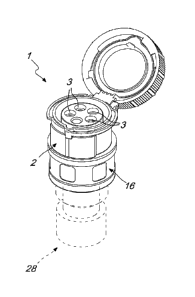
With reference to the cited figures, the compact interlocked electrical socket
according to the invention, globally designated by the reference numeral 1,
includes a
containment body 2 having a plurality of seats 3 for respective receptacles
adapted to
receive the pins of a plug, which is not shown in the figures.
CA 03003782 2018-05-01
WO 2017/198338 PCT/EP2017/000604
4
The seats 3 are provided in a cylindrical part 4 which is accommodated in the
containment body 2 in which a central body 5 is also engaged which acts as a
support
for a plurality of contact chains 6.
Each contact chain 6 includes a receptacle 7, having a corresponding
downstream fixed contact 8, and a terminal 9, having a respective upstream
fixed
contact 10.
The fixed contacts 8 and 10 are placed in mutual electrical contact by means
of a
movable contact 11.
The socket also includes a contact chain 61 for ground connection, which is
constituted by a receptacle 71 which is connected to a terminal 91 by means of
a blade
89 without discontinuity.
In each contact chain 6, the upstream fixed context 10 is connected to the
power
source and the downstream fixed contact 8 is connected to the load.
The movable contact 11 is pressed by a spring 12 in contrast with a movable
mechanical device and can be brought into contact alternately with the fixed
contacts 8
and 10 or spaced from them.
In the embodiment shown in the figures, in each contact chain 6, the upstream
fixed contact 10 is connected to the respective terminal 9, to which a power
supply
cable, not shown in the figures, is wired, while the downstream contact 8 is
connected to
the receptacle 7, i.e., to the female contact of the socket 1.
The upstream contacts 10 and the downstream contacts 8 are arranged along a
circumference.
The poles can be two, three or four, in addition to the ground, which is a
through
ground and is not disconnected.
The contact chains 6 of the various poles allow an advantageous execution of
the
closure and opening of the contacts by means of the movement of the movable
contacts
11.
Each movable contact 11 slides in a seat which makes the movable contact 11
move exclusively in a radial direction.
Each movable contact 11 is accommodated in a contact holder 13, which has the
CA 03003782 2018-05-01
WO 2017/198338 PCT/EP2017/000604
triple purpose of sliding along the seat, accommodating the spring 12 and
sliding against
a cam 14.
The movable contact 11 is kept pressed by the spring 12, which pushes it
toward
the fixed contacts 8 and 10.
5 The contrast spring 12 is calibrated so that when the contact is closed
it provides
the correct contact pressure between the movable contacts 11 and each fixed
contact 8,
10.
The opening operation is performed by the cams 14 provided on a cam disk 15.
The cam disk 15 rotates through a preset angle. The rotation of the cam disk
15,
which is limited by stroke limiters constituted by mechanical abutments,
causes the back
and forth translation of each contact holder 13 and with it of the respective
movable
contact 11. The term "forward" means that the
Figures 8 shows the cam disk 15 in the closed breaker position, in which the
contacts 11 are at the outward stroke limit; figure 9 shows the open breaker
position,
wherein the contacts 11 are at the stroke limit, toward the center.
The rotary motion for the actuation of the cam disk 15 is transmitted by an
external member which is constituted by a switching ring 16 which is held and
rotated.
The switching ring 16 contributes to constitute the enclosure of the socket
and
ensures the hermetic tightness, "IP rating", with an appropriate gasket
system.
Transmission of the motion between the switching ring 16, which is actuated by
hand, and the internal cam disk 15 can occur in two manners.
The simplest manner is that the two components are mutually integrally
coupled;
in this case the motion of the ring coincides with the motion of the internal
cams.
A second manner, which is more advantageous from a functional standpoint,
allows a so-called "independent switching" of the breaker in which there is no
relation
between the speed of the external switching, imposed by the hand, and the
speed of
movement of the contacts.
This second manner is the preferred embodiment of the present invention.
The switching ring 16 is provided with pusher members 17 which, when the ring
rotates, begin to compress two switching springs 18 which are accommodated in
the
CA 03003782 2018-05-01
WO 2017/198338 PCT/EP2017/000604
6
cam disk 15, which is initially coupled and unable to rotate.
The rotation of the switching ring 16, in view of the constraint of the cam
disk 15,
compresses progressively the switching springs 18.
The rotation of the cam disk 15 is prevented by a system of lugs 19, which
engage slots 20 provided in the central body 5, which is a fixed part of the
socket 1.
A pair constituted by a lug 19 and a slot 20 locks the cam disk 15 in a "0"
position, i.e., in the open contact position, while the second pair
constituted by the lug 19
and the slot 20 blocks the cam disk 15 in the "1" position, i.e., in the
closed contact
position.
The rotation of the switching ring 16, in the absence of the rotation of the
cam
disk 15, produces a progressive compression of the switching springs 18 until,
when a
given rotation angle has been reached, brackets 21 formed within the switching
ring 12
extract the lug 19 of the cam disk 15 from the corresponding slot 20.
At this point the cam disk 15, which is no longer constrained and pressed by
the
switching springs 18 at their point of maximum compression, rotates at a speed
that is
determined by forces and frictions but not by the hand of the operator, the
movement of
which has by now ended.
Pushed by the switching springs 18, the cam disk 15 rotates rapidly until it
arrives
at a mechanical stop.
The rotation of the cam disk 15, as described above, actuates the movable
contacts 11 by means of the cams 14.
In its final position, the second lug 19 engages the second slot 20. This
engagement prevents the rotation of the cam disk 15 in the opposite direction
when one
proceeds with the reverse switching.
The opening and closing switching is perfectly symmetrical.
Figures 10 and 11 show the switching springs 18 in the rest position / maximum
extension position (Figure 11) and in the compression position (Figure 10).
According to the present invention, the socket 1 also has a mechanical
socket/plug interlock, which has the dual function of preventing the actuation
of the
breaker in ON mode, if the plug is not inserted, and of preventing the
extraction of the
CA 03003782 2018-05-01
WO 2017/198338 PCT/EP2017/000604
7
plug if the breaker is in the ON mode.
As in conventional interlocked sockets, the interlock system makes the
following
sequences mandatory: inserting the plug and then operating the breaker to the
ON
position, in order to perform the electrical connection, and operating the
breaker in the
OFF position and extracting the pin, in order to break the electrical
connection.
The interlock system includes a slider 22 with a return spring 23 which is
arranged in the interspace between the cylindrical part 4 and the enclosure 2.
When the plug is extracted, the slider 22 is in the position in which the
return
spring 23 is extended.
As can be seen in Figure 7, in this position the internal head 24 of the
slider 22
engages a contrast member 25 of the switching ring 16, preventing its rotation
and
consequently the actuation of the breaker to the ON mode.
When the plug is inserted, its annular part 100, shown in dashes, presses
against
the slider 22, making it shift and compressing the return spring 23. Once the
shifting has
been completed, the internal head 25 disengages from the contrast member 25 of
the
switching ring 16, allowing its rotation and consequently the actuation of the
breaker to
the ON mode.
The interlock system also includes a hook 26, which is formed in the switching
ring 16 and is adapted to interact with a lug 101 provided on the plug, which
has
standardized dimensions and positions.
As described above, when the plug is inserted it is possible to rotate the
switching ring 16 to the breaker ON position. This rotation moves the hook 26
to a
position that traps the lug 101, as visible in Figure 7.
The switching ring 16 contributes to form the enclosure of the socket, which
must
protect the electrical contacts from the penetration of liquids and solids
("IP" rating). This
function is obtained by means of gaskets 27 which are arranged between the
switching
ring 16 and the core of the socket.
In the use of the interlocked socket as an inline socket, the socket assembly
is
associated with a grip 28, shown with broken lines in Figure 1.
The socket assembly, without the grip 28, can be mounted on a wall or on an
8
electrical panel by means of adapted systems of flanges and sliders.
In practice it has been found that the invention achieves the intended aims
and objects,
an interlocked electrical socket having being provided which is extremely more
compact than
traditional interlocked sockets and at the same time is easy to use.
This application claims the priority of Italian Patent Application No.
UA2016A003614
(corresponding to No. 102016000051784), filed on May 19, 2016.
Date Recue/Date Received 2020-05-27