Note: Descriptions are shown in the official language in which they were submitted.
CA 03004240 2018-05-03
TECHNIQUES FOR BENCHMARKING PAIRING STRATEGIES IN A CONTACT
CENTER SYSTEM
FIELD OF THE DISCLOSURE
This disclosure generally relates to contact centers and, more particularly,
to techniques
for benchmarking pairing strategies in a contact center system.
BACKGROUND OF THE DISCLOSURE
A typical contact center algorithmically assigns contacts arriving at the
contact center
to agents available to handle those contacts. At times, the contact center may
have agents
available and waiting for assignment to inbound or outbound contacts (e.g.,
telephone calls,
Internet chat sessions, email) or outbound contacts. At other times, the
contact center may have
contacts waiting in one or more queues for an agent to become available for
assigntnent.
1
CA 03004240 2018-05-03
WO 2017/182879 PCT/I132017/000570
In some typical contact centers, contacts are assigned to agents ordered based
on time
of arrival, and agents receive contacts ordered based on the time when those
agents became
available. This strategy may be referred to as a "first-in, first-out",
"FIFO", or "round-robin"
strategy.
Some contact centers may use a "performance based routing" or "PBR" approach
to
ordering the queue of available agents or, occasionally, contacts. PBR
ordering strategies
attempt to maximize the expected outcome of each contact--agent interaction
but do so
typically without regard for utilizing agents in a contact center uniformly.
When a contact center changes from using one type of pairing strategy (e.g.,
FIFO) to
another type of pairing strategy (e.g., PBR), overall contact center
performance will continue
to vary over time. It can be difficult to measure the amount of performance
change
attributable to using a new pairing strategy because there may be other
factors that account
for some of the increased or decreased performance over time.
In view of the foregoing, it may be understood that there is a need for a
system that
enables benchmarking of alternative routing strategies to measure changes in
performance
attributable to the alternative routing strategies.
SUMMARY OF THE DISCLOSURE
Techniques for benchmarking pairing strategies in a contact center system are
disclosed. In one particular embodiment, the techniques may be realized as a
method for
benchmarking pairing strategies in a contact center system comprising:
cycling, by at least
one processor configured for contact center operations, among at least two
pairing strategies;
and determining, by the at least one processor, a difference in performance
between the at
least two pairing strategies, wherein at least one contact was paired in a
sequence of contact
interactions to reach a final outcome during a final contact interaction of
the sequence of
2
CA 03004240 2018-05-03
WO 2017/182879 PCT/1B2017/000570
contact interactions.
In accordance with other aspects of this particular embodiment, a final
outcome
indicator for each of the sequence of contact interactions may indicate the
final outcome
determined from the final contact interaction of the sequence of contact
interactions.
In accordance with other aspects of this particular embodiment, a pairing
strategy
indicator for each of the sequence of contact interactions may indicate which
of the at least
two pairing strategies was used for pairing each of the sequence of contact
interactions.
In accordance with other aspects of this particular embodiment, an iteration
indicator
for each of the sequence of contact interactions may indicate a sequence
iteration number in
which each of the sequence of contact interactions occurred.
In accordance with other aspects of this particular embodiment, determining
the
difference in performance may further comprise: determining, by the at least
one processor,
an intermediate measure of performance for each set of contact interactions
indicated by a
same sequence iteration number; and determining, by the at least one
processor, an overall
difference in performance based on a combination of the intermediate measure
of
performance for each set of contact interactions for all sequence iteration
numbers.
In accordance with other aspects of this particular embodiment, the
combination is a
weighted average of the intermediate measure of performance for each set of
contact
interactions.
In accordance with other aspects of this particular embodiment, the method may
further comprise: determining, by the at least one processor, each arrival
time of the at least
one contact; and selecting, by the at least one processor, one of the at least
two pairing
strategies for each arrival time of the at least one contact based on each
arrival time and
irrespective of any prior pairings for the at least one contact.
In another particular embodiment, the techniques may be realized as a system
for
3
CA 03004240 2018-05-03
WO 2017/182879 PCT/I132017/000570
benchmarking pairing strategies in a contact center system comprising at least
one processor
configured for contact center operations, wherein the at least one processor
is configured to
perform the above-described method
In another particular embodiment, the techniques may be realized as an article
of
manufacture for benchmarking pairing strategies in a contact center system
comprising: a
non-transitory processor readable medium; and instructions stored on the
medium; wherein
the instructions are configured to be readable from the medium by at least one
processor
configured for contact center operations and thereby cause the at least one
processor to
operate so as to perform the above-described method.
The present disclosure will now be described in more detail with reference to
particular embodiments thereof as shown in the accompanying drawings. While
the present
disclosure is described below with reference to particular embodiments, it
should be
understood that the present disclosure is not limited thereto. Those of
ordinary skill in the art
having access to the teachings herein will recognize additional
implementations,
1.5 modifications, and embodiments, as well as other fields of use,
which are within the scope of
the present disclosure as described herein, and with respect to which the
present disclosure
may be of significant utility.
BRIEF DESCRIPTION OF THE DRAWINGS
In order to facilitate a fuller understanding of the present disclosure,
reference is now
made to the accompanying drawings, in which like elements are referenced with
like
numerals. These drawings should not be construed as limiting the present
disclosure, but are
intended to be illustrative only.
FIG. lA shows a schematic representation of a benchmarking sequence according
to
embodiments of the present disclosure.
4
CA 03004240 2018-05-03
WO 2017/182879 PCT/1B2017/000570
FIG. 1B shows a schematic representation of benchmarking sequence according to
embodiments of the present disclosure.
FIG. 2A shows a schematic representation of benchmarking sequence according to
embodiments of the present disclosure.
FIG. 2B shows a schematic representation of benchmarking sequence according to
embodiments of the present disclosure.
FIG. 3A shows a schematic representation of benchmarking sequence according to
embodiments of the present disclosure.
FIG. 3B shows a schematic representation of benchmarking sequence according to
embodiments of the present disclosure.
FIG. 3C shows a block diagram of a contact center system according to
embodiments
of the present disclosure.
FIG. 3D shows a block diagram of a behavioral pairing module according to
embodiments of the present disclosure.
FIG. 4 shows a block diagram of a contact center according to embodiments of
the
present disclosure.
FIG. 5 shows a flow diagram of a benchmarking method according to embodiments
of
the present disclosure.
FIG. 6 depicts a block diagram of a benchmarking module according to
embodiments
of the present disclosure.
FIG. 7A shows a schematic representation of benchmarking sequence according to
embodiments of the present disclosure.
FIG. 7B shows a schematic representation of benchmarking sequence according to
embodiments of the present disclosure.
FIG. 8 shows a flow diagram of a benchmarking method according to embodiments
of
5
CA 03004240 2018-05-03
WO 2017/182879 PCT/1132017/000570
the present disclosure.
DETAILED DESCRIPTION
A typical contact center algorithmically assigns contacts arriving at the
contact center
to agents available to handle those contacts. At times, the contact center may
have agents
available and waiting for assignment to inbound or outbound contacts (e.g.,
telephone calls,
Internet chat sessions, email) or outbound contacts. At other times, the
contact center may
have contacts waiting in one or more queues for an agent to become available
for assignment.
In some typical contact centers, contacts are assigned to agents ordered based
on time
of arrival, and agents receive contacts ordered based on the time when those
agents became
available. This strategy may be referred to as a "first-in, first-out",
"FIFO", or "round-robin"
strategy. For example, a longest-available agent pairing strategy preferably
selects the
available agent who has been available for the longest time.
Some contact centers may use a "performance based routing" or "PBR" approach
to
ordering the queue of available agents or, occasionally, contacts. PBR
ordering strategies
attempt to maximize the expected outcome of each contact-agent interaction but
do so
typically without regard for utilizing agents in a contact center uniformly.
Some variants of
PBR may include a highest-performing-agent pairing strategy, preferably
selecting the
available agent with the highest performance, or a highest-performing-agent-
for-contact-type
pairing strategy, preferably selecting the available agent with the highest
performance for the
type of contact being paired.
For yet another example, some contact centers may use a "behavioral pairing"
or
"BP" strategy, under which contacts and agents may be deliberately
(preferentially) paired in
a fashion that enables the assignment of subsequent contact-agent pairs such
that when the
benefits of all the assignments under a BP strategy are totaled they may
exceed those of FIFO
6
CA 03004240 2018-05-03
and PBR strategies. BP is designed to encourage balanced utilization of agents
within a skill
queue while nevertheless simultaneously improving overall contact center
performance beyond
what FIFO or PBR methods will allow. This is a remarkable achievement inasmuch
as BP acts
on the same calls and same agents as FIFO or PBR methods, utilizes agents
approximately
evenly as FIFO provides, and yet improves overall contact center performance.
BP is described
in, e.g., U.S. Patent Application No. 14/871,658, filed September 30, 2015.
Additional
information about these and other features regarding the pairing or matching
modules
(sometimes also referred to as "SATMAP", "routing system", "routing engine",
etc.) is
described in, for example, U.S. Patent No. 8,879,715.
Some contact centers may use a variety of other possible pairing strategies.
For
example, in a longest-available agent pairing strategy, an agent may be
selected who has been
waiting (idle) the longest time since the agent's most recent contact
interaction (e.g., call) has
ended. In a least-occupied agent pairing strategy, an agent may be selected
who has the lowest
ratio of contact interaction time to waiting or idle time (e.g., time spent on
calls versus time
spent off calls). In a fewest-contact-interactions-taken-by-agent pairing
strategy, an agent may
be selected who has the fewest total contact interactions or calls. In a
randomly-selected-agent
pairing strategy, an available agent may be selected at random (e.g., using a
pseudorandom
number generator). In a sequentially-labeled-agent pairing strategy, agents
may be labeled
sequentially, and the available agent with the next label in sequence may be
selected.
In situations where multiple contacts are waiting in a queue, and an agent
becomes
available for connection to one of the contacts in the queue, a variety of
pairing strategies may
be used. For example, in a FIFO or longest-waiting-contact pairing strategy,
the agent may be
preferably paired with the contact that has been waiting in queue the longest
(e.g., the
7
CA 03004240 2018-05-03
WO 2017/182879 PCT/1132017/000570
contact at the head of the queue). In a randomly-selected-contact pairing
strategy, the agent
may be paired with a contact selected at random from among all or a subset of
the contacts in
the queue. In a priority-based routing or highest-priority-contact pairing
strategy, the agent
may be paired with a higher-priority contact even if a lower-priority contact
has been waiting
in the queue longer.
Contact centers may measure performance based on a variety of metrics. For
example,
a contact center may measure performance based on one or more of sales
revenue, sales
conversion rates, customer retention rates, average handle time, customer
satisfaction (based
on, e.g., customer surveys), etc. Regardless of what metric or combination of
metrics a
contact center uses to measure performance, or what pairing strategy (e.g.,
FIFO, PBR, BP) a
contact center uses, performance may vary over time. For example, year-over-
year contact
center performance may vary as a company shrinks or grows over time or
introduces new
products or contact center campaigns. Month-to-month contact center
performance may vary
as a company goes through sales cycles, such as a busy holiday season selling
period, or a
heavy period of technical support requests following a new product or upgrade
rollout. Day-
to-day contact center performance may vary if, for example, customers are more
likely to call
during a weekend than on a weekday, or more likely to call on a Monday than a
Friday.
Intraday contact center performance may also vary. For example, customers may
be more
likely to call at when a contact center first opens (e.g., 8:00 AM), or during
a lunch break
(e.g., 12:00 PM), or in the evening after typical business hours (e.g., 6:00
PM), than at other
times during the day. Intra-hour contact center performance may also vary. For
example,
more urgent, high-value contacts may be more likely to arrive the minute the
contact center
opens (e.g., 9:00 or 9:01) than even a little later (e.g., 9:05). Contact
center performance may
also vary depending on the number and caliber of agents working at a given
time. For
8
CA 03004240 2018-05-03
WO 2017/182879 PCT/1132017/000570
example, the 9:00-5:00 PM shift of agents may perform, on average, better than
the 5:00-
9:00 AM shift of agents.
These examples of variability at certain times of day or over larger time
periods can
make it difficult to attribute changes in performance over a given time period
to a particular
pairing strategy. For example, if a contact center used FIFO routing for one
year with an
average performance of 20% sales conversion rate, then switched to PBR in the
second year
with an average performance of 30% sales conversion rate, the apparent change
in
performance is a 500/o improvement. However, this contact center may not have
a reliable
way to know what the average performance in the second year would have been
had it kept
the contact center using FIFO routing instead of PBR. In real-world
situations, at least some
of the 50% gain in performance in the second year may be attributable to other
factors or
variables that were not controlled or measured. For example, the contact
center may have
retrained its agents or hired higher-performing agents, or the company may
have introduced
an improved product with better reception in the marketplace. Consequently,
contact centers
may struggle to analyze the internal rate of return or return on investment
from switching to a
different to a different pairing strategy due to challenges associated with
measuring
performance gain attributable to the new pairing strategy.
In some embodiments, a contact center may switch (or "cycle") periodically
among at
least two different pairing strategies (e.g., between FIFO and PBR; between
PBR and BP;
among FIFO, PBR, and BP). Additionally, the outcome of each contact¨agent
interaction
may be recorded along with an identification of which pairing strategy (e.g.,
FIFO, PBR, or
BP) had been used to assign that particular contact¨agent pair. By tracking
which interactions
produced which results, the contact center may measure the performance
attributable to a first
strategy (e.g., FIFO) and the performance attributable to a second strategy
(e.g., PBR). In this
way, the relative performance of one strategy may be benchmarked against the
other. The
9
CA 03004240 2018-05-03
WO 2017/182879 PCT/IB2017/000570
contact center may, over many periods of switching between different pairing
strategies,
more reliably attribute performance gain to one strategy or the other.
Several benchmarking techniques may achieve precisely measurable performance
gain by reducing noise from confounding variables and eliminating bias in
favor of one
pairing strategy or another. In some embodiments, benchmarking techniques may
be time-
based ("epoch benchmarking"). In other embodiments, benchmarking techniques
may
involve randomization or counting ("inline benchmarking"). In other
embodiments,
benchmarking techniques may be a hybrid of epoch and inline benchmarking.
In epoch benchmarking, as explained in detail below, the switching frequency
(or
period duration) can affect the accuracy and fairness (e.g., statistical
purity) of the
benchmark. For example, assume the period is two years, switching each year
between two
different strategies. In this case, the contact center may use FIFO in the
first year at a 20%
conversion rate and PBR in the second year at a 30% conversion rate, and
measure the gain
as 50%. However, this period is too large to eliminate or otherwise control
for expected
variability in performance. Even shorter periods such as two months, switching
between
strategies each month, may be susceptible to similar effects. For example, if
FIFO is used in
November, and PBR is used December, some performance improvement in December
may
be attributable to increased holiday sales in December rather than the PBR
itself.
In some embodiments, to reduce or minimize the effects of performance
variability
over time, the period may be much shorter (e.g., less than a day, less than an
hour, less than
twenty minutes). FIG. IA shows a benchmarking period of ten units (e.g., ten
minutes). In
FIG. 1A, the horizontal axis represents time, and the vertical axis represents
whether a first
pairing strategy ("1") or a second pairing strategy ("0") is used. For the
first five minutes
(e.g., 9:00-9:05 AM), the first pairing strategy (e.g., BP) may be used. After
five minutes, the
contact center may switch to the second pairing strategy (e.g., FIFO or PBR)
for the
CA 03004240 2018-05-03
WO 2017/182879 PCT/I132017/000570
remaining five minutes of the ten-minute period (9:05-9:10 AM). At 9:10 AM,
the second
period may begin, switching back to the first pairing strategy (not shown in
FIG. IA). If the
period is 30 minutes (i.e., each unit of time in FIG. IA is equal to three
minutes), the first
pairing strategy may be used for the first 15 minutes, and the second pairing
strategy may be
used for the second 15 minutes.
With short, intra-hour periods (10 minutes, 20 minutes, 30 minutes, etc.), the
benchmark is less likely to be biased in favor of one pairing strategy or
another based on
long-term variability (e.g., year-over-year growth, month-to-month sales
cycles). However,
other factors of performance variability may persist. For example, if the
contact center always
applies the period shown in FIG. IA when it opens in the morning, the contact
center will
always use the first strategy (BP) for the first five minutes. As explained
above, the contacts
who arrive at a contact center the moment it opens may be of a different type,
urgency, value,
or distribution of type/urgency/value than the contacts that arrive at other
times of the hour or
the day. Consequently, the benchmark may be biased in favor of the pairing
strategy used at
the beginning of the day (e.g., 9:00 AM) each day.
In some embodiments, to reduce or minimize the effects of performance
variability
over even short periods of time, the order in which pairing strategies are
used within each
period may change. For example, as shown in FIG. 1B, the order in which
pairing strategies
are used has been reversed from the order shown in FIG. IA. Specifically, the
contact center
may start with the second pairing strategy (e.g., FIFO or PBR) for the first
five minutes, then
switch to the first pairing strategy (BP) for the following five minutes.
In some embodiments, to help ensure trust and fairness in the benchmarking
system,
the benchmarlcing schedule may be established and published or otherwise
shared with
contact center management ahead or other users of time. In some embodiments,
contact
center management or other users may be given direct, real-time control over
the
11
CA 03004240 2018-05-03
WO 2017/182879 PCT/1B2017/000570
benchmarking schedule, such as using a computer program interface to control
the cycle
duration and the ordering of pairing strategies.
Embodiments of the present disclosure may use any of a variety of techniques
for
varying the order in which the pairing strategies are used within each period.
For example,
the contact center may alternate each hour (or each day or each month) between
starting with
the first ordering shown in FIG. IA and starting with the second ordering
shown in FIG. 1B.
In other embodiments, each period may randomly select an ordering (e.g..
approximately
50% of the periods in a given day used the ordering shown in FIG. 1A, and
approximately
50% of the periods in a given day use the ordering shown in FIG. 1B, with a
uniform and
random distribution of orderings among the periods).
In the examples of FIGS. 1 A and 1B, each pairing strategy is used for the
same
amount of time within each period (e.g., five minutes each). In these
examples, the "duty
cycle" is 50%. However, notwithstanding other variables affecting performance,
some
pairing strategies are expected to perform better than others. For example, BP
is expected to
1 5 perform better than FIFO. Consequently, a contact center may wish to
use BP for a greater
proportion of time than FIFO¨so that more pairings are made using the higher-
performing
pairing strategy. Thus, the contact center may prefer a higher duty cycle
(e.g., 60%, 70%,
80%, 90%, etc.) representing more time (or proportion of contacts) paired
using the higher-
performing pairing strategy. FIG. 2A shows an example of a ten-minute period
with an 80%
duty cycle. For the first eight minutes (e.g., 9:00-9:08 AM), the first
pairing strategy (e.g.,
BP) may be used. After the first eight minutes, the contact center may switch
to the second
pairing strategy (e.g., FIFO) for the remaining two minutes of the period
(9:08-9:10) before
switching back to the first pairing strategy again (not shown). If, for
another example, a
thirty-minute period is used, the first pairing strategy may be used for the
first twenty-four
12
CA 03004240 2018-05-03
WO 2017/182879 PCT/I132017/000570
minutes (e.g., 9:00-9:24 AM), and the second pairing strategy may be used for
the next six
minutes (e.g., 9:24-9:30 AM).
As shown in FIG. 2B, the contact center may proceed through six ten-minute
periods
over the course of an hour. In this example, each ten-minute period has an 80%
duty cycle
.. favoring the first pairing strategy, and the ordering within each period
starts with the favored
first pairing strategy. Over the hour, the contact center may switch pairing
strategies twelve
times (e.g., at 9:08, 9:10, 9:18, 9:20, 9:28, 9:30, 9:38, 9:40, 9:48, 9:50,
9:58, and 10:00).
Within the hour, the first pairing strategy was used a total of 800/o of the
time (48 minutes),
and the second pairing strategy was used the other 20% of the time (12
minutes). For a thirty-
.. minute period with an 80% duty cycle (not shown), over the hour, the
contact center may
switch pairing strategies four times (e.g., at 9:24, 9:30, 9:48, and 10:00),
and the total remains
48 minutes using the first pairing strategy and 12 minute using the second
pairing strategy.
In some embodiments, as in the example of FIG. 1B, the order in which the
pairing
strategies are used within a period may change (not shown), even as the duty
cycle
.. (percentage of time within the period that a given strategy is used)
remains the same.
Nevertheless, for periods which are factors or multiples of 60 minutes (e.g.,
10 minutes, 30
minutes), periods may always or frequently align to boundaries at the top of
each hour (e.g.,
new periods begin at 9:00, 10:00, 11:00, etc.), regardless of the ordering of
pairing strategies
to be used for the period at the beginning of a given hour.
In some embodiments, as explained below with references to FIGS. 3A-D,
choosing a
period such as 11 minutes, 37 minutes, some prime or other numbers that do not
factor into
60-minute intervals, can increase the number of periods required before a
particular pattern
repeats. Instead, the alignment of periods may drift through hours, days,
weeks, etc. before
repeating. The duration of a cycle through each pairing strategy may align
infrequently with
to the hours of a day, days of a week, weeks of a month or year, etc.
13
CA 03004240 2018-05-03
WO 2017/182879 PCT/I132017/000570
FIG. 3A shows an example of a single non-factor period of 11 minutes and
approximately a 73% duty cycle, with the first eight minutes using a first
pairing strategy and
the last three minutes using a second pairing strategy. FIG. 3B illustrates
six consecutive
cycles. For example, at the top of the first hour on the first day of the week
(e.g., Monday at
9:00 AM), the first period may begin, aligned on the top of the hour, the
first hour of the day,
and the first day of the week. The first period may last from 9:00-9:11 AM,
followed by the
second period from 9:11-9:22 AM, and so on, as illustrated in FIG. 3B and
Table I below.
The sixth period begins at 9:55 and ends at 10:06. The top of the second hour
(10:00 AM),
occurs during the sixth cycle and is not aligned with the beginning of a
period. FIG. 3C
shows the same six periods as FIG. 3B, with the horizontal axis marking time
on ten-minute
intervals to illustrate the intentional intra-hour misalignment further.
Table I
Period # Time Period Begins
1 9:00
9:11
3 9:22
4 9:33
5 9:44
6 9:55
7 10.06
As shown in FIG. 3D and Table II below, the alignment of periods with respect
to the
nearest hour continues to drift throughout a day, using an example of a
contact center open
from 9:00 AM to 5:00 PM (9:00-17:00 hours). The first period of the first hour
(9:00 AM) is
14
CA 03004240 2018-05-03
WO 2017/182879 PCT/I132017/000570
aligned with the top of the hour (9:00 AM). The first period of the second
hour (10:00 AM)
begins at 10:06 AM, six minutes after the top of the hour. The first period of
the third hour
(11:00 AM) bens at 11:01 AM, one minute after the top of the hour. It would
take 60
periods over 11 hours for the first period of an hour to once again align with
the top of the
hour. As shown in Table II, a contact center that is open from 9-5 would not
be aligned on
the hour again until 12:00 PM the following day (1.375 eight-hour days later).
Table II
Hour Time of First Period of Hour
1 9:00
2 10:06
3 11:01
4 12:07
5 13:02
6 14:08
7 15:03
8 16:09
(next day)
9 9:04
10:10
11 11:05
12 12:00
Table III below shows the sequence of days and times at which a new period
begins at
10 the top of the hour. For example, assuming five-day weeks Monday¨Friday
with eight-hour
CA 03004240 2018-05-03
WO 2017/182879 PCT/I132017/000570
days from 9-5, the sequence would proceed from aligning on Monday at 9:00 AM,
to
Tuesday at 12:00 PM, to Wednesday at 3:00 PM (15:00), to Friday at 10:00 AM,
and so on.
As shown in Table III, it would take 2.2 weeks for a contact center that is
open five days per
week for eight hours per day to be aligned at the beginning of a day (e.g.,
Tuesday at
9:00 AM over two weeks later).
Table HI
Day Next Time Period Starts at I op of Hour
Monday 9:00
Tuesday 12:00
Wednesday 15:00
Friday 10:00
(next week)
Monday 13:00
Tuesday 16:00
Thursday 11:00
Fri day 14:00
(next week)
Tuesday 9:00
Table IV below shows the sequence of days of the week on which a new period
begins at the top of that day of the week. In this example, assuming five-day
weeks Monday-
Friday with eight-hour days, the sequence would proceed from aligning with the
beginning of
the day on Monday in week 1, Tuesday in week 3, Wednesday in week 5, and so
on. As
16
CA 03004240 2018-05-03
WO 2017/182879 PCT/1B2017/000570
shown in Table IV, it would take 11 weeks for this contact center to be
aligned at the
beginning of a Monday again.
Table IV
Week Next Day Cycle Starts at Top of Day
1 Monday
3 Tuesday
Wednesday
7 Thursday
9 Friday
12 Monday
5 Thus,
as FIGS. 3A-3D and Tables I-IV have illustrated, selecting a non-factor period
for an hour/day/week/etc. boundary may be effective for enabling the alignment
of periods to
"drift" through natural time boundaries over weeks/months/years. Because the
alignment of
periods drifts, it is less likely for a pattern to arise that confounds
measuring relative
performance of multiple pairing strategies. In some embodiments, selection of
a non-factor
period may be combined with other techniques for reducing the effect of
confounding
variables on performance, such as randomizing or otherwise changing the
ordering of pairing
strategies within each period or a set of periods
In some embodiments, the contact center may determine which pairing strategy
to use
based on the time at which a pairing request is made for a contact. For
example, assume a
contact center is benchmarking BP and FIFO using the example of FIG IA (ten-
minute
periods with a 50% duty cycle, starting with BP in the first half and FIFO in
the second half).
If the contact center requests a pairing at 9:04 AM, the time of the pairing
falls in the first
17
CA 03004240 2018-05-03
WO 2017/182879 PCT/I132017/000570
half of a period, so the BP strategy may be used. If the contact center
requests a pairing at
9:06 AM, the time of the pairing falls in the second half of the period, so
the FIFO strategy
may be used.
In other embodiments, the contact center may determine which pairing strategy
to use
based on the time at which a contact arrives. For example, assume a contact
center is
benchmarking BP and FIFO as in the preceding example. If the first contact
arrives at
9:04 AM, the time of arrival falls in the first half of a period, so the BP
strategy may be used
for the contact. Even if the first contact must wait in a queue for two
minutes, and the pairing
is not requested until 9:06 AM, the pairing may still be made using the BP
strategy.
Moreover, if a second contact arrives at 9:05 AM, while the first contact is
still waiting in
queue, the second contact may be designated for FIFO pairing. Consequently, at
9:06 AM,
contact choice under behavioral pairing may be limited to only the contacts in
queue who
arrived during the BP portion of the period and, in this example, only the
first contact to
arrive would be available.
In embodiments for epoch-based benchmarking in which a contact arrives on a
boundary between periods, or on a boundary between switching pairing
strategies within a
period, the system may have predetermined tie-breaking strategies. For
example, the
boundary may be defined as "at or before" an aforementioned time, or "on or
after" an
aforementioned time, etc. For example, if a period is defined to be associated
with strategy
"A" from 9:00-9:08 and strategy B from 9:08-9:10, it may mean that a contact
must arrive
on or after 9:00 but before 9:08 (e.g., 9:07.99) to be considered within the
first part of the
period. Alternatively, it may mean that a contact must arrive after 9:00 but
at or before
9:08.00 to be considered within the first part of the period.
In some embodiments, inline benchmarking techniques may be used, in which
pairing
strategies may be selected on a contact-by-contact basis. For example, assume
that
18
CA 03004240 2018-05-03
WO 2017/182879 PCT/I132017/000570
approximately 50% of contacts arriving at a contact center should be paired
using a first
pairing method (e.g., FIFO), and the other 50% of contacts should be paired
using a second
pairing method (e.g., BP).
In some embodiments, each contact may be randomly designated for pairing using
one method or the other with a 50% probability. In other embodiments, contacts
may be
sequentially designated according to a particular period. For example, the
first five (or ten, or
twenty, etc.) contacts may be designated for a FIFO strategy, and the next
five (or ten, or
twenty, etc.) may be designated for a BP strategy. Other percentages and
proportions may
also be used, such as 60% (or 80%, etc.) paired with a BP strategy and the
other 40% (or
20%, etc.) paired with a FIFO strategy.
From time to time, a contact may return to a contact center (e.g., call back)
multiple
times. In particular, some contacts may require multiple "touches" (e.g.,
multiple interactions
with one or more contact center agents) to resolve an issue. In these cases,
it may be desirable
to ensure that a contact is paired using the same pairing strategy each time
the contact returns
to the contact center. If the same pairing strategy is used for each touch,
then the
benchmarking technique will ensure that this single pairing strategy is
associated with the
final outcome (e.g., resolution) of the multiple contact¨agent interactions.
In other situations,
it may be desirable to switch pairing strategies each time a contact returns
to the contact
center, so that each pairing strategy may have an equal chance to be used
during the pairing
that resolves the contact's needs and produces the final outcome. In yet other
situations, it
may be desirable to select pairing strategies without regard to whether a
contact has contacted
the contact center about the same issue multiple times.
In some embodiments, the determination of whether a repeat contact should be
designated for the same (or different) pairing strategy may depend on other
factors. For
example, there may be a time limit, such that the contact must return to the
contact center
19
CA 03004240 2018-05-03
WO 2017/182879 PCT/1132017/000570
within a specified time period for prior pairing strategies to be considered
(e.g., within an
hour, within a day, within a week). In other embodiments, the pairing strategy
used in the
first interaction may be considered regardless of how much time has passed
since the first
interaction.
For another example, repeat contact may be limited to specific skill queues or
customer needs. Consider a contact who called a contact center and requested
to speak to a
customer service agent regarding the contact's bill. The contact hangs up and
then calls back
a few minutes later and requests to speak to a technical support agent
regarding the contact's
technical difficulties. In this case, the second call may be considered a new
issue rather than a
second "touch" regarding the billing issue. In this second call, it may be
determined that the
pairing strategy used in the first call is irrelevant to the second call. En
other embodiments, the
pairing strategy used in the first call may be considered regardless of why
the contact has
returned to the contact center.
One approach to considering prior pairing for inline benchmarking techniques
is
depicted in FIG. 4. FIG. 4 shows a flow diagram of benchmarking method 400
according to
embodiments of the present disclosure. Benchmarking method 400 may begin at
block 410.
At block 410, an identifier of a contact (e.g., caller) may be identified or
otherwise
determined. In this example, a caller's "Billing Telephone Number" or "BTN"
may be
identified. This example assumes that a caller uses the same BTN for each
call. In other
embodiments, other identifiers of the contact (e.g., a customer identification
number, Internet
Protocol (IP) address) may be used instead. Having identified the caller's BTN
(or other
contact identifier), benchmarking method 400 may proceed to block 420.
At block 420, a pseudorandom number generator (PRNG) may be seeded with the
BTN (or other contact identifier). Having seeded the PRNG with the BTN,
benchmarking
method 400 may proceed to block 430.
CA 03004240 2018-05-03
WO 2017/182879 PCT/1B2017/000570
At block 430, a pseudorandom number may be generated for the contact using the
seeded PRNG. Because the seed will be the same for a given contact each time
the contact
returns to the contact center, the generated pseudorandom number will also be
the same each
time for the given contact. Having generated the pseudorandom number,
benchmarking
method 400 may proceed to block 440.
At block 440, a pairing strategy (e.g., BP or FIFO) may be selected for the
given
contact based on the generated pseudorandom number. For example, if 50% of
contacts
should be paired using BP, and the other 50% should be paired using FIFO, the
PRNG may
be configured to generate either a 1 or a 0. If the generated pseudorandom
number is a 1, the
contact may be designated for BP pairing. If the generated pseudorandom number
is 0, the
contact may be designated for FIFO pairing.
In this way, the contact will always be paired using the same strategy each
time the
contact returns to the contact center. The PRNG will be seeded with the same
seed (e.g., the
contact's BIN) each time, so the PRNG will generate the same pseudorandom
number for
the contact each time. Thus, benchmarking method 400 may select the same
pairing strategy
for the contact each time. In this way, it is possible to account for prior
pairings without
relying on a database or other storage means to determine whether or how a
contact has been
previously paired. In this way, benchmarking method 400 is stateless with
respect to whether
or how a contact has been previously paired. Having selected a pairing
strategy for the
contact, benchmarking method 400 may proceed to block 450.
At block 450, the contact may be paired to an available agent using the
selected
pairing strategy. When a contact has been paired with an available agent,
components of the
contact center system (e.g., switches, routers) may connect the contact to the
agent.
Following (or during) the contact¨agent interaction, the agent may create a
record of the
outcome of the interaction. For example, in a sales queue, the agent may
create an order for
21
CA 03004240 2018-05-03
WO 2017/182879 PCT/I132017/000570
the contact. In a technical support queue, the agent may create or modify a
service ticket. The
contact center system may also record information about the interaction, such
as the time and
duration of a call, the BTN or other identifier of the contact, the agent
identifier, and other
data. At this point, benchmarking method may proceed to block 460.
At block 460, an identifier of the selected pairing strategy may be associated
with the
record of the contact¨agent interaction created at block 450. In some
embodiments, this may
happen simultaneously with the creation of the record. For example, when the
contact center
system records the time and duration of a call, it may also record whether the
call had been
paired using a BP or FIFO pairing strategy. In other embodiments, another
module may
create a separate record of the pairing. This module may record the time of
the pairing, the
contact and agent identifiers, the pairing strategy used (e.g., BP or FIFO),
and any other data
that may be helpful for later matching the pairing record with the record of
the caller--agent
interaction outcome. At some later time, the pairing records may be matched
with the caller¨
agent interaction records so that the pairing strategy information may be
associated with the
outcome in one record or the other (or both). Following block 460,
benchmarking method
400 may end. In some embodiments, benchmarking method 400 may return to block
410,
waiting for another contact to arrive.
Another approach to considering prior pairing in combination with epoch
benchmarking techniques is depicted in FIG. 5. This type of technique may be
considered
"hybrid inline¨epoch benchmarking." FIG. 5 shows a flow diagram of
benchmarking method
500 according to embodiments of the present disclosure. Benchmarking method
500 may
begin at block 510.
At block 510, a contact (e.g., "contact n") arrives at the contact center at a
particular
time t. Benchmarking method 500 may proceed to block 520.
22
CA 03004240 2018-05-03
WO 2017/182879 PCT/1132017/000570
At block 520, it may be determined whether the contact has been previously
paired;
i.e., whether this contact is returning to the contact center for a subsequent
touch or
interaction. This decision may be made using a variety of techniques. For
example, the
benchmarking system may look up the contact's records using a contact
identifier (e.g., BTN
or customer ID) in a database to determine whether and when the contact had
previously
contacted the contact center. Using a suitable technique, the benchmarking
system may
determine that the contact had been previously paired and, in some
embodiments, whether
and how the prior pairing should influence the current pairing.
In some embodiments, the benchmarking system may preferably pair a contact
using
the same pairing strategy every time the contact returns to the contact
center. Thus, if contact
n was previously paired using pairing strategy "A" (e.g., BP), benchmarking
method 500 may
proceed to block 560 for subsequent pairing using pairing strategy A again.
Similarly, if
contact n was previously paired using pairing strategy "B") (e.g., FIFO),
benchmarking
method 500 may proceed to block 570 for subsequent pairing using pairing
strategy B again
However, if it is determined at block 520 that contact,: has not been
previously paired
(or, in some embodiments, any prior pairing should not influence the current
pairing),
benchmarking method 500 may proceed to using epoch benchmarking at block 550.
At block 550, time may be used to determine which pairing strategy to use for
contact
n. In this example, arrival time t may be used. If contact n arrived during a
time period when
the benchmarking system is pairing using strategy A, benchmarking method 500
may
proceed to block 560 for subsequent pairing using strategy A. Similarly, if
contact n arrived
during a time period when the benchmarking system is pairing using strategy B,
benchmarking method 500 may proceed to block 570 for subsequent pairing using
strategy B.
At blocks 560 and 570, contacts may be paired to available agents using
pairing
strategies A or B, respectively. In some embodiments, more than two pairing
strategies may
23
CA 03004240 2018-05-03
WO 2017/182879 PCT/I132017/000570
be used (e.g., prior pairings using A, B, C, etc. or epoch benchmarking within
time periods
using A, B, C, etc.). Once paired, the contact may be routed or otherwise
connected to the
available agent within the contact center system. As described above with
respect to
benchmarking method 400 (FIG. 4), the agent may create a record of the
contact¨agent
interaction, and the contact center system may also create or modify this
record.
Benchmarking method may proceed to block 580.
At block 580, an identifier to the selected pairing strategy (e.g., A or B)
may be
associated with the record created at block 560 or 570. As described above
with respect to
benchmarking method 400, this association may occur simultaneously with the
creation of
the contact¨agent interaction record, or it may be matched at a later time
with other records
created by a benchmarking module or other module. Following block 580,
benchmarking
method 500 may end. In some embodiments, benchmarking method 500 may return to
block
510, waiting for another contact to arrive.
By associating the pairing strategy with the outcome as in, for example,
benchmarking methods 400 and 500, the outcomes associated with each pairing
strategy may
be measured (e.g., averaged, accumulated), and the relative performance of
each pairing
strategy may be measured (e.g., the relative overall performance gain
attributable to pairing
using BP instead of pairing using FIFO). This benchmarking data may be used
for a variety
of purposes. For example, the data may be used to assess the strength of one
pairing module
.. over another. For another example, the data may be used to improve the
strength of a BP
module by providing "BP on" and "BP off' (e.g., FIFO) contact¨agent
interaction records to
enhance the artificial intelligence in the system. For another example, the
data may be used
for billing. Because the value added by one pairing strategy over another may
be measured
accurately and fairly, this benchmarking data may be used in a pay-for-
performance business
model, in which a client pays a pairing strategy vendor a percentage of the
actual measured
24
CA 03004240 2018-05-03
WO 2017/182879 PCT/1B2017/000570
value added by using the vendor's pairing strategy (e.g., when BP is on as
opposed to when
BP is off).
Specifically, in some embodiments, associated outcome data may be used to
determine an economic value or gain associated with using one pairing strategy
instead of
another. In some embodiments, the economic value or gain may be used to
determine
compensation for a vendor or other service provider providing a module or
modules for the
higher-performing pairing strategy creating the economic value. For example,
if a contact
center benchmarks BP against FIFO and determines that, for a given time period
(e.g., a day,
a week, a month, etc.), that BP performed 5% better than FIFO on average over
the time
period, the BP vendor may receive compensation corresponding to the 5% value
added by BP
(e.g., a percentage of the 5% additional sales revenue, or a percentage of the
5% additional
cost savings, etc.). Under such a business model, a contact center owner may
forgo capital
expenditure or vendor fees, only paying a vendor for periods of time in which
the vendor
demonstrates value added to the contact center's performance
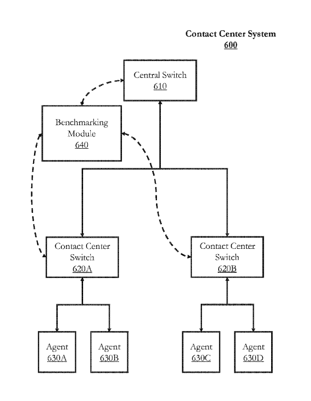
FIG. 6 shows a block diagram of a contact center system 600 according to
embodiments of the present disclosure. The description herein describes
network elements,
computers, and/or components of a system and method for simulating contact
center systems
that may include one or more modules. As used herein, the term "module" may be
understood to refer to computing software, firmware, hardware, and/or various
combinations
thereof. Modules, however, are not to be interpreted as software which is not
implemented on
hardware, firmware, or recorded on a processor readable recordable storage
medium (i.e.,
modules are not software per se). It is noted that the modules are exemplary.
The modules
may be combined, integrated, separated, and/or duplicated to support various
applications.
Also, a function described herein as being performed at a particular module
may be
performed at one or more other modules and/or by one or more other devices
instead of or in
CA 03004240 2018-05-03
WO 2017/182879 PCT/I132017/000570
addition to the function performed at the particular module. Further, the
modules may be
implemented across multiple devices and/or other components local or remote to
one another.
Additionally, the modules may be moved from one device and added to another
device,
and/or may be included in both devices.
As shown in FIG. 6, the contact center system 600 may include a central switch
610.
The central switch 610 may receive incoming contacts (e.g., callers) or
support outbound
connections to contacts via a telecommunications network (not shown). The
central switch
610 may include contact routing hardware and software for helping to route
contacts among
one or more contact centers, or to one or more PBX/ACDs or other queuing or
switching
.. components within a contact center.
The central switch 610 may not be necessary if there is only one contact
center, or if
there is only one PBVACD routing component, in the contact center system 600.
If more
than one contact center is part of the contact center system 600, each contact
center may
include at least one contact center switch (e.g., contact center switches 620A
and 620B). The
contact center switches 620A and 620B may be communicatively coupled to the
central
switch 610.
Each contact center switch for each contact center may be communicatively
coupled
to a plurality (or "pool") of agents. Each contact center switch may support a
certain number
of agents (or "seats") to be logged in at one time. At any given time, a
logged-in agent may
be available and waiting to be connected to a contact, or the logged-in agent
may be
unavailable for any of a number of reasons, such as being connected to another
contact,
performing certain post-call functions such as logging information about the
call, or taking a
break.
In the example of FIG. 6, the central switch 610 routes contacts to one of two
contact
centers via contact center switch 620A and contact center switch 620B,
respectively. Each of
26
CA 03004240 2018-05-03
WO 2017/182879 PCT/I132017/000570
the contact center switches 620A and 620B are shown with two agents each.
Agents 630A
and 630B may be logged into contact center switch 620A, and agents 630C and
630D may be
logged into contact center switch 620B.
The contact center system 600 may also be communicatively coupled to an
integrated
service from, for example, a third party vendor. In the example of FIG. 6,
benchmarking
module 640 may be communicatively coupled to one or more switches in the
switch system
of the contact center system 600, such as central switch 610, contact center
switch 620A, or
contact center switch 620B. In some embodiments, switches of the contact
center system 600
may be communicatively coupled to multiple benchmarking modules. In some
embodiments,
benchmarking module 640 may be embedded within a component of a contact center
system
(e.g., embedded in or otherwise integrated with a switch). The benchmarking
module 640
may receive information from a switch (e.g., contact center switch 620A) about
agents logged
into the switch (e.g., agents 630A and 630B) and about incoming contacts via
another switch
(e.g., central switch 610) or, in some embodiments, from a network (e.g., the
Internet or a
telecommunications network) (not shown).
A contact center may include multiple pairing modules (e.g., a BP module and a
FIFO
module) (not shown), and one or more pairing modules may be provided by one or
more
different vendors. In some embodiments, one or more pairing modules may be
components of
benchmarking module 640 or one or more switches such as central switch 610 or
contact
center switches 620A and 620B. In some embodiments, a benchmarking module may
determine which pairing module may handle pairing for a particular contact.
For example, the
benchmarking module may alternate between enabling pairing via the BP module
and
enabling pairing with the FIFO module. In other embodiments, one pairing
module (e.g., the
BP module) may be configured to emulate other pairing strategies. For example,
a
benchmarking module, or a benchmarking component integrated with BP components
in the
27
CA 03004240 2018-05-03
WO 2017/182879 PCT/I132017/000570
BP module, may determine whether the BP module may use BP pairing or emulated
FIFO
pairing for a particular contact. In this case, "BP on" may refer to times
when the BP module
is applying the BP pairing strategy, and "BP oft" may refer to other times
when the BP
module is applying a different pairing strategy (e.g., FIFO).
In some embodiments, regardless of whether pairing strategies are handled by
separate modules, or if some pairing strategies are emulated within a single
pairing module,
the single pairing module may be configured to monitor and store information
about pairings
made under any or all pairing strategies. For example, a BP module may observe
and record
data about FIFO pairings made by a FIFO module, or the BP module may observe
and record
data about emulated FIFO pairings made by a BP module operating in FIFO
emulation mode.
Embodiments of the present disclosure are not limited to benchmarking only two
pairing strategies. Instead, benchmarking may be performed for two or more
pairing
strategies. FIGS. 7A and 7B depict examples of benchmarking systems for three
pairing
strategies (e.g., benchmarking FIFO, PBR, and BP)
FIG. 7A shows a schematic representation of benchmarking sequence according to
embodiments of the present disclosure. In this epoch benchmarking example, a
period is 15
units of time, and each pairing strategy is used for one-third of the time (5
units). FIG. 7A
shows two complete periods, cycling among pairing strategies "2", "1", and "0"
twice over
30 units of time. For example, from 9:00-9:10 AM, FIFO may be used; from 9:10-
9:20 AM,
PBR may be used; and from 9:20-9:30 AM, BP may be used. This pattern of FIFO-
PBR-BP
repeats in the second period.
FIG. 7B shows a schematic representation of benchmarking sequence according to
embodiments of the present disclosure. In this epoch benchmarking example, a
complete
period is 30 time units. A preferred pairing strategy "2" (e.g., BP) is used
two-thirds of the
time, and other pairing strategies "1" and "0" (e.g., FIFO and PBR) are used
one-sixth of the
28
CA 03004240 2018-05-03
WO 2017/182879 PCT/I132017/000570
time each. In this example, each time strategy "2" turns off, pairing
strategies "1" and "0"
alternately turn on. For example, the pattern may be BP-FIFO-BP-PBR. In
addition to the
examples of FIGS. 7A and 7B, many other patterns for switching among multiple
pairing
strategies are possible.
In some embodiments, contact center management or other users may prefer a
"stabilization period" or other neutral zone. For example, consider a contact
center
benchmarking BP and FIFO pairing strategies. When the system transitions from
BP to FIFO
(or vice versa), contact center management may be concerned that the effects
of one pairing
strategy may somehow influence the performance of another pairing strategy. To
alleviate
these concerns about fairness, a stabilization period may be added.
One technique for implementing a stabilization period may be to exclude
contact¨
agent interaction outcomes for the first portion of contacts after switching
pairing strategies.
For example, assume a contact center is benchmarking BP and FIFO with a 50%
duty cycle
over 30-minute periods. In the aforementioned embodiments (e.g., FIGS. IA and
1B), BP
would be on for 15 minutes, followed by FIFO for 15 minutes, and all of the
contact¨agent
interactions in the 30-minute period would be included in the benchmarking
measurement.
With a stabilization period, BP would be on for, e.g., 10 minutes. After 10
minutes, the
system would switch to FIFO. However, the first, e.g., 10 minutes would be
considered a
stabilization period, and FIFO pairings made during this period would be
excluded from the
benchmark. The last 10 minutes of the period would continue pairing using
FIFO, and these
FIFO pairings would be included in the benchmark.
This pattern is illustrated in FIG. 7A. In this example, instead of depicting
switching
among three pairing strategies "2", "1", and "0", the "1" may represent the
stabilization
period. Pairing strategy "2" (e.g., BP) may be on for the first five time
units. After five time
units, BP may be switched off, and the other pairing strategy (e.g., FIFO) may
be used for the
29
CA 03004240 2018-05-03
WO 2017/182879 PCTAB2017/000570
remaining ten time units. The next five units ("1") may be excluded as being
part of the
stabilization period, and the five time units after that ("0") may be included
as being part of
the FIFO benchmarking period.
In some embodiments, the stabilization period may be longer or shorter. In
some
.. embodiments, a stabilization period may be used in a FIFO-to-BP transition
instead of, or in
addition to, a BP-to-FIFO transition (or any transition between two different
pairing
strategies).
As noted above, some contacts may require multiple "touches" (e.g., multiple
interactions with one or more contact center agents) to resolve the contact's
needs. For
example, an individual may call or otherwise contact a mortgage bank several
times. The first
call may be merely introductory or informational in nature, the second call
may be to evaluate
different loan offers, and the third call may be to close (accept) or decline
a loan offer.
Similarly, some technical support and customer service requests may require
more than one
contact interaction to resolve.
In some situations, it may be desirable to select pairing strategies without
regard to
whether a contact has contacted the contact center about the same issue
multiple times.
Instead, the benchmarking technique may be configured to account for each
pairing strategy.
For example, each pairing strategy may be credited in a manner that fairly
accounts for the
extent to which it may have contributed to the series of contact interactions
that resulted in a
final outcome or resolution of the contact's needs.
FIG. 8 shows a flow diagram of benchmarking method 800 according to
embodiments
of the present disclosure. Benchmarking method 800 may begin at block 810.
At block 810, a contact (e.g., "contact n") arrives at the contact center at a
particular
time t and a particular iteration i. For example, if this time is the first
time contact n has
.. contacted the contact center about this particular need, it will be
designated the first iteration
CA 03004240 2018-05-03
WO 2017/182879 PCT/M2017/000570
(i.e., 1), or this time may be the second (i = 2), third (i = 3), ...1h
time calling.
Benchmarking method 800 may proceed to block 820.
At block 820, time may be used to determine which pairing strategy to use for
contact
it. In these embodiments, even if this is a subsequent arrival such that 1> 1,
the pairing
strategy selected for any prior pairing need not influence the current
pairing. In this example,
arrival time t may be used. If contact n arrived during a time period when the
benchmarking
system is pairing using strategy A, benchmarking method 800 may proceed to
block 830 for
subsequent pairing using strategy A. Similarly, if contact ti arrived during a
time period when
the benchmarking system is pairing using strategy B, benchmarking method 800
may proceed
to block 840 for subsequent pairing using strategy B. In some embodiments,
pairing strategy
A may be a behavioral pairing strategy (behavioral pairing "ON"), and pairing
strategy B
may be a different pairing strategy such as FIFO or performance-based routing
(behavioral
pairing "OFF").
At blocks 830 and 840, contacts may be paired to available agents using
pairing
strategies A or B, respectively. In some embodiments, more than two pairing
strategies may
be used. Once paired, the contact may be routed or otherwise connected to the
available agent
within the contact center system. As described above with respect to
benchmarking methods
400 (FIG. 4) and 500 (FIG. 5), the agent may create a record of the
contact¨agent interaction,
and the contact center system may also create or modify this record.
Benchmarking method
may proceed to block 850.
At block 850, an identifier to the selected pairing strategy (e.g., A or B)
may be
associated with an identifier of the current iteration i for the contact n
within the record (or
set of records) created at block 830 or 840. As described above with respect
to benchmarking
methods 400 and 500, this association may occur simultaneously with the
creation of the
31
CA 03004240 2018-05-03
WO 2017/182879 PCT/1B2017/000570
contact-agent interaction record, or it may be matched at a later time with
other records
created by a benchmarking module or other module.
In some embodiments, benchmarking method 800 may proceed to block 860. At
block 860, it may be determined whether the needs of contact n have been
resolved. If the
needs of contact n have not yet been resolved, or in other embodiments where
the outcome of
a given call may be matched at a later time, benchmarking method 800 may end
or return to
block 810 for the next contact to arrive. If the needs of contact n have been
resolved,
benchmarking method 800 may proceed to block 870.
At block 870, the final outcome (e.g., a mortgage loan was closed or declined,
a sale
.. was completed or canceled) may be associated with the record or records for
each of the i
iterations for contact n. Table V shows an example set of records for four
contacts W, X, Y,
and Z, who each contacted the contact center system three times before
reaching a final
resolution. In real-world scenarios, there may be many more contacts, and the
number of
contact interactions needed to resolve an individual contact's needs may vary
from one
contact to the next, ranging from just one contact interaction to three or
even more.
Table V
Iteration i Contact W Contact X Contact Y Contact Z
A B A
2 B B A A
3 A A
Outcome Sale Sale Sale No Sale
As shown in Table V, and as described above with respect to block 850, the
identifiers for the contact (W, X, Y, or Z) and the iteration (1, 2, or 3) are
associated with the
32
CA 03004240 2018-05-03
WO 2017/182879 PCT/1132017/000570
selected pairing strategy used for the given contact interaction (A or B). For
contact W,
iteration I was paired with strategy A, iteration 2 was paired with strategy
B, and iteration 3
was paired with strategy A. For contact X, iteration 1 was paired with
strategy B, iteration 2
was paired with strategy B, and iteration 3 was paired with strategy A. For
contact Y,
iteration 1 was paired with strategy A, iteration 2 was paired with strategy
A, and iteration 3
was paired with strategy B. For contact Z, iteration 1 was paired with
strategy B, iteration 2
was paired with strategy A, and iteration 3 was paired with strategy B.
Also shown in Table V, and as described above with respect to block 870, the
final
outcome for the contact may be associated with the records for each iteration.
Contacts W, X,
and Y completed sales. Contact Z did not complete a sale. In some embodiments,
a "no sale"
determination may be made if the contact explicitly states that it does not
intend to complete
a sale. In other embodiments, the contact center system may make a "no sale"
determination
after a predetermined number of iterations have occurred without completing a
sale, or after a
predetermined amount of time has passed since the most recent iteration
without completing
a sale. In some situations, such as when a contact has resolved a technical
support or
customer service need, the final resolution may be a customer satisfaction
survey result or
score.
Following block 870, benchmarking method 800 may end In some embodiments,
benchmarking method 800 may return to block 810, waiting for another contact
to arrive
(e.g., a different contact, or contact n with a new need).
On a continuous, hourly, daily, weekly, etc. basis, a difference in
performance among
pairing strategies may be determined. In some embodiments, the performance
difference may
be stratified for each iteration (the performance difference for all contact
interactions of
iteration i = 1; all contact interactions of iteration i = 2; etc.). Although
a final resolution may
not have been reached after the first contact interaction (when i = 1), the
benchmark for the
33
CA 03004240 2018-05-03
WO 2017/182879 PCT/I132017/000570
first stratum may be measured using the final outcome, which was previously
associated with
that first contact interaction either at block 870 or matched at a later time
with other contact
center system records.
Using the example shown in Table V, for the benchmark for the first stratum
(1= 1),
two contacts (W and Y) were paired using strategy A for the first iteration,
and both had final
outcomes resulting in a sale, achieving a conversion rate of 100%. The other
two contacts (X
and Z) were paired using strategy B for the first iteration, and only one (X)
had a final
outcome resulting in a sale, achieving a conversation rate of 50%.
Similarly, for the benchmark for the second stratum (i = 2), two contacts (Y
and Z)
were paired using strategy A for the second iteration, and only one (Y) had a
final outcome
resulting in a sale, achieving a conversation rate of 50%. The other two
contacts (W and X)
were paired using strategy B for the second iteration, and both had final
outcomes resulting in
a sale, achieving a conversion rate of 100%.
Finally, for the benchmark for the third stratum (i = 3), two contacts (NV and
X) were
paired using strategy A for the third iteration, and both had final outcomes
resulting in a sale,
achieving a conversion rate of 100%. The other two contacts (Y and Z) were
paired using
strategy B for the third iteration, and only one (Y) had a final outcome
resulting in a sale,
achieving a conversion rate of 50%.
These strata and conversion rates are shown in Table VI below:
Table VI
Iteration/Stratum i Strategy A Strategy B
1 100% 50%
2 50% 100%
3 100% 50%
34
CA 03004240 2018-05-03
WO 2017/182879 PCT/I132017/000570
After determining performances or performance differences between each pairing
strategy for each iteration (based on the final outcomes), the performance
differences may be
combined. In some embodiments, the performance differences may be averaged. In
the
example of Table V, the average conversion rate for strategy A is
approximately 83%, and
the average conversion rate for strategy B is approximately 67%. Strategy A
performed
almost 24% better than strategy B. In some embodiments, the performance
differences may
be normalized based on the total number of contact interactions for each
strategy for each
iteration.
In some embodiments, some iterations may be weighted more or less than other
iterations. For example, it may be determined (by, e.g., contact center system
administrators
or other business leaders) that the first contact interaction is the most
critical to determining
whether or to what extent a desirable final outcome will be achieved. In other
situations, it
may be determined that the final contact interaction is the most critical. In
these situations,
the more critical strata may be weighted more heavily than less critical
strata in the final
benchmarking result.
At this point it should be noted that behavioral pairing in a contact center
system in
accordance with the present disclosure as described above may involve the
processing of
input data and the generation of output data to some extent. This input data
processing and
output data generation may be implemented in hardware or software. For
example, specific
electronic components may be employed in a behavioral pairing module or
similar or related
circuitry for implementing the functions associated with behavioral pairing in
a contact center
system in accordance with the present disclosure as described above.
Alternatively, one or
more processors operating in accordance with instructions may implement the
functions
associated with behavioral pairing in a contact center system in accordance
with the present
CA 03004240 2018-05-03
WO 2017/182879 PCT/1B2017/000570
disclosure as described above. If such is the case, it is within the scope of
the present
disclosure that such instructions may be stored on one or more non-transitory
processor
readable storage media (e.g., a magnetic disk or other storage medium), or
transmitted to one
or more processors via one or more signals embodied in one or more carrier
waves.
The present disclosure is not to be limited in scope by the specific
embodiments
described herein. Indeed, other various embodiments of and modifications to
the present
disclosure, in addition to those described herein, will be apparent to those
of ordinary skill in
the art from the foregoing description and accompanying drawings. Thus, such
other
embodiments and modifications are intended to fall within the scope of the
present
disclosure. Further, although the present disclosure has been described herein
in the context
of at least one particular implementation in at least one particular
environment for at least one
particular purpose, those of ordinary skill in the art will recognize that its
usefulness is not
limited thereto and that the present disclosure may be beneficially
implemented in any
number of environments for any number of purposes. Accordingly, the claims set
forth below
should be construed in view of the full breadth and spirit of the present
disclosure as
described herein.
36