Note: Descriptions are shown in the official language in which they were submitted.
CA 03004428 2018-05-04
WO 2017/077345 PCT/GB2016/053479
1
Circulation Subassembly
This invention relates to circulation subassemblies employed in the oil and
gas drilling industry.
BACKGROUND
It is known to provide circulation subassemblies (circsubs) in drill pipes in
the oil and gas
industry. Such circsubs allow drilling fluid that is pumped down the drill
pipe to bypass the
bottom hole assembly (BHA) by providing an opening that can selectively allow
fluid
communication between the bore of the drill pipe and the annulus between the
drill pipe and the
well bore. This may be useful if an operator wishes to clean part of the
annulus with drilling fluid
at high flow rate. It may also be useful for introducing lost circulation
material (LCM) to seal the
well bore and prevent loss of drilling fluid. It is undesirable to introduce
LCM around the BHA, as
this may cause the BHA to become stuck.
Known circsubs may be actuated by a variety of different methods, including by
passing a dart
or a ball down the bore of the drill pipe. However, this method has the
disadvantage that the
darts or balls can often only be passed down the bore of the drill string when
drilling fluid is able
to flow down the drill pipe.
Some circsubs only allow partial bypass of the BHA. That is, they selectively
allow or prevent
fluid communication between the bore of the drill pipe and the annulus between
the drill pipe
and the well bore, but they cannot prevent fluid communication between the
bore of the drill
pipe above the circsub and the BHA. It is desirable to provide the possibility
of both full bypass
in which fluid communication between the bore of the drill pipe and the BHA is
prevented but
fluid communication between the bore of the drill pipe and the annulus is
allowed and partial
bypass. However, this increases complexity.
A known circsub, which is available from Drilling Systems International (DS!)
under the trade
name PBLO Sub, is operable to provide full bypass of a BHA. It is placed in
the full bypass
condition by passing a vinyl ball down the bore of the drill pipe. The tool
can be returned to the
flow through condition by inserting deactivation balls to block the bypass
holes and increasing
the pressure to a predetermined value, which causes the vinyl ball to shear
and move through
the circsub to a catcher assembly. The deactivation balls also move through
the circsub to the
catcher assembly. A disadvantage of this arrangement is that transitions
between conditions
can only be made when drilling fluid is able to flow through the circsub, and
the number of
transitions that are possible before the circsub must be removed from the well
bore is limited by
the space available to store used balls.
The present invention seeks to at least partially mitigate the problems
identified with the prior
art.
CA 03004428 2018-05-04
WO 2017/077345 PCT/GB2016/053479
2
BRIEF SUMMARY OF THE DISCLOSURE
In accordance with an aspect of the present invention there is provided a
circulation
subassembly (circsub) for incorporation in a drill pipe, the circsub
comprising a piston movable
within a bore of the circsub in a first direction by pressure of fluid within
said bore, the piston
having:
a first position corresponding to a flow through condition of the circsub in
which the circsub
allows fluid to flow through a bore of the circsub and does not allow fluid
flow from the bore of
the circsub through bypass orifices in the circsub into an annulus located
outside the drill pipe;
a second position corresponding to a partial bypass condition of the circsub
in which the
circsub allows fluid to flow through the bore of the circsub and allows fluid
communication
through said bypass orifices from the bore of the circsub into the annulus;
and
a third position corresponding to a full bypass condition of the circsub in
which the circsub
does not allow fluid to flow through the bore of the circsub and allows fluid
communication
through said bypass orifices from the bore of the circsub into the annulus,
wherein the circsub further comprises biasing means for biasing the piston in
a second direction
opposite to the first direction, and a selectively adjustable abutment for
limiting the movement of
the piston in said first direction to each of said first, second and third
positions.
It will be understood that the piston may be substantially hollow, and at
least part of the bore of
the circsub may be a bore of the piston. An outer surface of the piston may be
in contact with
an inner surface of an outer body of the circsub.
A circsub produced in accordance with this aspect may allow an operator to
change between
the flow through, partial bypass and full bypass conditions without inserting
a dart or a ball into
the drill pipe. Accordingly, transitions between conditions may be made when
flow in the drill
pipe or the annulus is blocked, and a large number of transitions may be
possible without the
need for the circsub to return to the surface.
In accordance with another aspect of the invention there is provided a
circulation subassembly
(circsub) for incorporation in a drill pipe, the circsub comprising a piston
movable within a bore
of the circsub in a first direction by pressure of fluid within said bore, the
piston having:
a position corresponding to a flow through condition of the circsub in which
the circsub allows
fluid to flow through a bore of the circsub and does not allow fluid flow from
the bore of the
circsub through bypass orifices in the circsub into an annulus located outside
the drill pipe; and
a position corresponding to a full bypass condition of the circsub in which
the circsub
does not allow fluid to flow through the bore of the circsub and allows fluid
communication
through said bypass orifices from the bore of the circsub into the annulus,
wherein the circsub
CA 03004428 2018-05-04
WO 2017/077345 PCT/GB2016/053479
3
further comprises biasing means for biasing the piston in a second direction
opposite to the first
direction, and a selectively adjustable abutment for limiting the movement of
the piston in said
first direction to each of said positions.
In an embodiment the circsub further comprises an electronic controller and an
actuator
operable to move the adjustable abutment, the controller being operable:
in response to receipt of a first signal, to control the actuator to move the
adjustable
abutment so as to stop movement of the piston when the piston is in the first
position;
in response to receipt of a second signal, to control the actuator to move the
adjustable abutment so as to stop movement of the piston when the piston is in
the second
position; and
in response to receipt of a third signal, to control the actuator to move the
adjustable
abutment so as to stop movement of the piston when the piston is in the third
position.
In some embodiments the controller may be electrically powered by a power
source that is
separate from surface level when the circulation subassembly is in use in a
drill pipe. For
example, one or more batteries may be used to power the controller.
In an embodiment the adjustable abutment is configured to be automatically
moved once the
pressure falls below a threshold value. Optionally, the circsub further
comprises a barrel cam
and follower which causes relative rotation between the adjustable abutment
and the piston
when the pressure of fluid in the circsub rises and falls below the threshold
value.
Optionally, the adjustable abutment comprises a first castellated surface and
a second
castellated surface, one of which is defined on the piston, wherein the
actuator may be
configured to move the first castellated surface relative to the second
castellated surface,
thereby to effect the transitions between the flow through condition, the
partial bypass condition
and the full bypass condition. Preferably, the adjustable abutment comprises a
sleeve on which
the first castellated surface is defined, wherein movement of the castellated
surface comprises
rotation of the sleeve.
In some embodiments the actuator may comprise a motor configured to rotate the
sleeve.
Alternatively, the actuator may comprise one or more controllable valves
operable to move the
adjustable abutment by allowing or preventing flow of pressurised fluid into
one or more
actuation channels.
The biasing means may comprise a spring.
CA 03004428 2018-05-04
WO 2017/077345 PCT/GB2016/053479
4
In some embodiments the circsub further comprises a first sensor in
communication with the
controller, the first sensor being configured to detect mechanical signals
transmitted through the
drill pipe from surface level,
wherein the first, second and third signals correspond to predetermined
mechanical
signals being detectable by said first sensor.
Optionally, the first sensor may comprise one or more accelerometers. Use of
mechanical
signals may obviate the need for an electrical connection between the circsub
and a user
interface located at surface level. Furthermore, in embodiments where the
actuator and the
controller are powered by a power source that is separate from surface level
when the circsub is
in use it may be unnecessary to provide any electrical connection between the
circsub and
components located at surface level.
Further optionally, the first signal may correspond to a first predetermined
mechanical signal
being received when the circsub is in the full bypass condition, the second
signal corresponds
to a second predetermined mechanical signal being received when the circsub is
in the flow
through condition and the third signal corresponds to a third predetermined
mechanical signal
being received when the circsub is in the partial bypass condition, optionally
wherein the first,
second and third predetermined mechanical signals are the same as each other.
Accordingly,
the first controller may only be required to recognize a single predetermined
signal, and the
condition to which the controller changes the circsub in response to detecting
the predetermined
signal may depend on the condition of the circsub when the signal is received.
Optionally, the circsub further comprises a pressure sensor in communication
with the
controller, the pressure sensor being configured to detect a pressure in the
bore of the circsub,
wherein the controller is configured to prevent transitions between the flow
through, partial
bypass and full bypass conditions when the pressure measured by the prssure
sensor is above
a first threshold value. This may prevent the controller from attempting to
actuate a change in
condition of the circsub before the operator has reduced the pressure to the
level at which
transitions are expected to take place.
In some embodiments the circsub further comprises a proximity sensor in
communication with
the controller, the proximity sensor being configured to detect a position of
a piston of the
circsub, wherein the controller is configured to prevent transitions between
the flow through,
partial bypass and full bypass conditions in dependence on the position of the
piston. This may
prevent the controller from attempting to actuate a change in condition of the
circsub when the
castellated surfaces abut each other.
CA 03004428 2018-05-04
WO 2017/077345 PCT/GB2016/053479
In some embodiments the circsub may comprise a valve having an open condition
in which flow
through the bore of the circsub is allowed and a closed condition in which
flow through the bore
of the circsub is substantially prevented, wherein the valve is configured to
assume the open
5 condition when the circsub is in the flow through condition or the
partial bypass condition and to
assume the closed condition when the circsub is in the full bypass condition.
Optionally, the
valve may be a ball valve. Optionally, the valve may completely prevent flow
through the bore
of the circsub when it is in the closed condition.
In some embodiments the valve is located within the circsub by a frangible
abutment, wherein
the frangible abutment is configured to break when the valve is in the closed
condition and the
pressure in the bore of the circsub is greater than a second threshold value,
the valve being
configured to move within the circsub to a position at which drilling fluid
may flow around the
valve when the frangible abutment breaks. This may prevent, or at least delay,
a requirement for
the circsub to return to surface level if the mechanism that actuates the ball
valve fails while the
circsub is in use.
The frangible abutment may be a frangible shear ring.
In some embodiments, the valve is a ball valve and grooves are provided on an
inner surface of
the bore of the circsub, said grooves being configured to facilitate movement
of drilling fluid
around the ball valve when the ball valve has moved to the position at which
drilling fluid may
flow around the ball valve in response to the frangible abutment breaking.
In some embodiments the circsub comprises a conduit between the bore of the
circsub and the
annulus, the conduit being closed when the circsub is in the flow through
condition, opened to a
first extent when the circsub is in the partial bypass condition and opened to
a second extent
when the circsub is in the full bypass condition, wherein opening the conduit
to the second
extent provides a lower resistance to flow between the bore of the circsub and
the annulus than
opening the conduit to the first extent.
According to another embodiment said bypass orifices comprise a first set of
one or more
bypass orifices, a second set of one or more bypass orifices and a third set
of one or more
bypass orifices, wherein:
when the piston is in the second position the first set of bypass orifices and
not the second
set of bypass orifices are aligned with the third set of bypass orifices,
thereby allowing fluid
communication between the bore and the annulus;
CA 03004428 2018-05-04
WO 2017/077345 PCT/GB2016/053479
6
when the piston is in the third position the second set of bypass orifices and
not the first
set of bypass orifices are aligned with the third set of bypass orifices,
thereby allowing fluid
communication between the bore and the annulus. This allows the resistance to
flow between
the bore and the annulus to be independently tuned for the partial bypass and
full bypass
positions.
Optionally, the resistance to flow from the bore to the annulus when the
piston is in the partial
bypass position may be greater than the resistance to flow from the bore to
the annulus when
the piston is in the full bypass position. This may be achieved, for example,
by making the area
available for flow through the first set of orifices smaller than the area
available for flow through
the second set of orifices.
An advantage of the above arrangement is that a clear pressure pulse may be
observable
when the piston arrives at the third position and the second and third sets of
orifices align with
one another. It will be understood that it may only be possible for fluid in
the bore to flow into
the annulus via the bypass orifices when either the first or second set of
orifices is aligned with
the third set of orifices.
Within the scope of this application two sets of orifices are considered to be
"aligned" with one
another if they at least partially overlap so that a fluid path is provided
through the aligned
orifices. Optionally, one or more seals may be provided to prevent fluid
communication
between the first and/or second sets of orifices and the third set of orifices
when the first and/or
second sets of orifices are not aligned with the third set of orifices.
Another advantage of the above embodiment is that the first and second sets of
orifices may
not be aligned with the third set of orifices for at least a portion of the
movement of the piston
from the partial bypass position to the full bypass position. This may reduce
the amount of fluid
power required to move the piston from the partial bypass position to the full
bypass position,
as it obviates the requirement to pump fluid into the annulus while the piston
moves from the
.. partial bypass position to the full bypass position.
In an embodiment the first and second sets of orifices may be located in the
piston and the
third set of orifices may be located in an outer body of the circsub.
Alternatively, the first and
second sets of orifices may be located in the outer body of the circsub and
the third set of
orifices may be located in the piston.
Some of the orifices may alternatively be referred to as nozzles.
CA 03004428 2018-05-04
WO 2017/077345 PCT/GB2016/053479
7
In an embodiment the valve is configured to assume the closed condition when
the piston is at
an intermediate position between the partial bypass position and the full
bypass position. This
prevents fluid from flowing down the bore when the piston is between the
intermediate position
and the full bypass position, which may reduce the amount of fluid power
required to move the
piston from the partial bypass position to the full bypass position, because
it prevents flow
through the bore when the piston is between the intermediate position and the
full bypass
position.
In another embodiment said bypass orifices comprise one or more bypass
orifices located in
said piston and one or more bypass orifices located in an outer body of the
circsub, wherein the
bypass orifices located in said piston at least partially overlap the bypass
orifices in the outer
body when the piston is in said second and third positions.
According to another aspect of the present invention there is provided a
circulation
subassembly (circsub) for incorporation in a drill pipe, the circsub having:
a flow through condition in which the circsub allows fluid to flow through a
bore of
the circsub and does not allow fluid communication between the bore of the
circsub and an
annulus located outside the drill pipe;
a partial bypass condition in which the circsub allows fluid to flow through
the bore of
the circsub and allows fluid communication between the bore of the circsub and
the annulus;
and
a full bypass condition in which the circsub does not allow fluid to flow
through the
bore of the circsub and allows fluid communication between the bore of the
circsub and the
annulus,
wherein the circsub comprises a controller and an actuator, the controller
being operable:
to control the actuator to transition the circsub to the flow through
condition in
response to receipt of a first signal;
to control the actuator to transition the circsub to the partial bypass
condition in
response to receipt of a second signal; and
to control the actuator to transition the circsub to the full bypass condition
in
response to receipt of a third signal. The controller may comprise a processor
connected to and
electronic memory.
According to another aspect of the present invention there is provided a
method of operating a
circsub as described above, wherein transitions between the flow through,
partial bypass and
full bypass conditions are effected by sequentially:
CA 03004428 2018-05-04
WO 2017/077345 PCT/GB2016/053479
8
reducing the pressure of fluid within said bore to a value at which the piston
no
longer abuts the adjustable abutment;
moving the selectively adjustable abutment; and
increasing the pressure to a value at which further movement of the piston is
limited
by the piston abutting the adjustable abutment.
According to another aspect of the present invention there is provided a valve
assembly for
controlling flow of fluid through a bore of a piston, the assembly comprising
a valve having a first
condition and a second condition, an actuation assembly for changing the valve
between the
first condition and the second condition, the piston, and a sleeve in which
the piston is located,
wherein:
the piston is movable to a first position, a second position and a third
position
relative to the sleeve, the second position being between the first and third
positions;
when the piston is moved from the second position to the third position the
actuation assembly
causes the valve to change from the first condition to the second condition;
when the piston is moved from the third position to the second position the
actuation
assembly causes the valve to change from the second condition to the first
condition; and
the actuation assembly does not change the condition of the valve when piston
is moved from
the second position to the first posit
In an embodiment the first condition is an open condition in which the valve
allows fluid to flow
through the bore of the piston and the second condition is a closed condition
in which the valve
does not allow fluid to flow through the bore of the piston.
Optionally the valve is a ball valve.
In an embodiment the movement of the piston relative to the sleeve comprises
translation.
In an embodiment the actuation assembly may comprise a control arm and a key,
wherein:
movement of the control arm relative to the piston causes the valve to change
between the first condition to the second condition;
when the piston is in the first position or the second position the key is
located
between a recess in the control arm and a recess in the piston, thereby
preventing relative
movement between the control arm and the piston;
movement of piston from the second position to the third position causes the
key to
move within the recess in the control arm to a position in which the key is
located between the
recess in the control arm and a recess in the sleeve and subsequently causes
the control arm to
CA 03004428 2018-05-04
WO 2017/077345 PCT/GB2016/053479
9
move relative to the piston; and
movement of piston from the third position to the second position causes the
control
arm to move relative to the piston and subsequently causes the key to move
within the recess in
the control arm to a position in which the key is located between the recess
in the control arm
and the recess in the piston.
The key may have one or more cam surfaces, which cam surfaces are configured
to cause the
key to move within the recess in the control arm when the piston is moved
between the second
position and the third position.
In an embodiment there is provided a circsub as described above comprising a
valve assembly
as described above.
BRIEF INTRODUCTION OF THE DRAWINGS
An embodiment of the invention is further described hereinafter, by way of
example, with
reference to the accompanying drawings, in which:
Figure 1 shows a cross section of a circsub in an embodiment of the present
invention when the circsub is in a flow through condition;
Figure 2 shows a cross section of a circsub in an embodiment of the present
invention when the circsub is in a partial bypass condition;
Figure 3 shows a cross section of a circsub in an embodiment of the present
invention when the circsub is in a full bypass condition;
Figure 4 shows an enlarged version of a portion of the cross section shown in
figure 3;
Figure 5 shows a circsub in an embodiment of the present invention when the
circsub is in a flow through condition;
Figure 6 shows a partial cutaway of a circsub in an embodiment of the present
invention when the circsub is in a flow through condition;
Figure 7 shows a partial cutaway of a circsub in an embodiment of the present
invention when the circsub is in a partial bypass condition;
Figure 8 shows a partial cutaway of a circsub in an embodiment of the present
invention when the circsub is in a full bypass condition;
Figure 9 shows a circsub in an embodiment of the present invention when the
circsub is in a flow through condition;
Figures 10a-c show cross sections through a sliding control arm of a circsub
in an
embodiment of the present invention;
CA 03004428 2018-05-04
WO 2017/077345 PCT/GB2016/053479
Figure 11 shows a controller for controlling an actuator of a circsub in an
embodiment of the present invention;
Figure 12 shows a cross section of a circsub in another embodiment of the
present invention when the circsub is in a flow through condition;
5 Figure 13 shows a cross section of a circsub in another embodiment
of the
present invention when the circsub is in a flow through condition;
Figure 14 shows a cross section of the circsub shown in figure 13 when the
circsub is in a partial bypass condition;
Figure 15 shows a cross section of the circsub shown in figure 13 when the
10 circsub is in an intermediate position between the partial bypass
condition and
the full bypass condition;
Figure 16 shows a cross section of the circsub shown in figure 13 when the
circsub is in a full bypass condition; and
Figure 17 shows another cross section of the circsub shown in figure 13 when
the
circsub is in the intermediate position between the partial bypass condition
and
the full bypass condition.
DETAILED DESCRIPTION
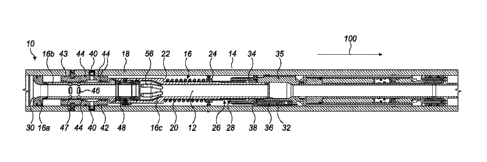
Figure 1 shows a cross sectional view of circsub 10 which is incorporated into
a drill string,
which comprises a drill pipe above the circsub 10 (not shown) and a bottom
hole assembly (not
shown) located below the circsub 10. Further drill pipe and other
subassemblies may be located
between the circsub and the BHA. The drill string shown in figure 1 is
drilling a horizontal well
bore in the direction indicated by arrow 100. Accordingly, the "bottom" of the
well bore being
drilled in figure 1 is actually the rightmost portion of it.
Circsub 10 comprises a piston 16 (which is formed in three parts 16a, 16b, 16c
that are rigidly
connected together) that is able to slide axially inside drill pipe portion
18. Spring 20 is arranged
to engage shoulder 22 of piston 16 and abutment 24, which is rigidly attached
to drill pipe
portion 18. Spring 20 therefore biases piston 16 up the drill string (i.e. in
the opposite direction
to that indicated by arrow 100). When the circsub 10 is in use high pressure
drilling fluid is
typically located in bore 12. The axial force due to the fluid pressure acting
on upper end 30 of
piston 16 is greater than that acting on lower end 32 of piston 16. This is
because the axial
component of the surface area of upper end 30, which is sealingly received
within the bore of
the drill pipe portion 18, is greater than that of lower end 32, which is
sealingly received within a
motor housing 35, itself fixed in, and sealed to, the drill pipe portion 18.
Accordingly, the
pressure of the fluid located in bore 12 acts to oppose spring 2.
As best illustrated in figure 5, if the fluid pressure in bore 12 is
sufficient to overcome spring 20
then axial movement of the piston 16 in the direction of arrow 100 is limited
by abutment of
CA 03004428 2018-05-04
WO 2017/077345 PCT/GB2016/053479
11
castellated surfaces 26 on the piston with corresponding castellated surfaces
28 on sleeve 34,
which is connected to the motor housing 35, as described further below. The
stiffness of spring
20 may be selected so that in normal drilling use the force due to the
pressure of the drilling
fluid is sufficient to overcome the force applied by the spring.
Sleeve 34 has a circumferentially disposed toothed rack (not easily visible in
the drawings) that
is engaged by a pinion 38 of a motor 36 (which may have an integral gearbox).
Motor 36 is
operable to rotate sleeve 34 about the piston 16, thereby to change the
angular position of
engagement between the castellated surfaces 26, 28. In this respect, it is
pointed out that the
piston 16, while being free to move axially, is angularly fixed in the drill
pipe portion 18. Motor
36 is powered by suitable batteries (not shown) located in circsub 10, and is
controlled by
controller 80 (see figure 11), which controller may also be powered by
batteries located in the
circsub 10. As will be understood by the skilled person, the batteries used to
power motor 36
and controller 80 must capable of operating in the conditions of temperature
and pressure that
are likely to be encountered when drilling down hole.
In the condition illustrated in figure 1 the sleeve 34 is in a first
rotational position that does not
allow castellated surfaces 26, 28 to interdigitate at all. This causes the
castellated surfaces 26,
28 to abut one another before apertures 46, 47 in the piston 16 align with the
inlet of nozzle 40.
Accordingly, fluid is not able to pass from the bore 12 to the annulus 14,
which is a space
defined between the outer surface of the circsub 12 and the inner surface of
the well bore (not
shown). Nozzle 40 is located on sleeve 43, which is bolted to drill pipe
portion 18. Annular seals
44 are provided around nozzle 40 to prevent leakage of fluid when apertures
46, 47 are not
aligned with the inlet of nozzle 40. A ball valve 48 is provided further down
the circsub than
apertures 46, 47. In the configuration shown in figure 1 the ball valve 48 is
in an open condition.
The condition illustrated in figure 1 is therefore a flow through condition,
which allows drilling
fluid to flow through the bore 12, and does not allow fluid communication
between the bore 12
and the annulus 14.
Figure 2 shows a cross sectional view of the circsub 10 illustrated in figure
1 in a partial bypass
condition which allows drilling fluid to flow through the bore 12, but also
allows some drilling fluid
to pass from the bore 12 to the annulus 14.
In the condition illustrated in figure 2 the sleeve 34 has been rotated to a
second position, which
allows castellated surfaces 26, 28 to partially interdigitate. Accordingly,
the movement of piston
16 is limited at an axial position that is further down the drill pipe than
was the case in the flow
through condition illustrated in figure 1. This allows aperture 46 (but not
aperture 47) to align
with the inlet of nozzles 40. When apertures 46 align with nozzles 40 they
provide a conduit
between the bore 12 and the annulus 14, so when apertures 46 are aligned with
the inlet of
nozzles 40 some of the drilling fluid located in the bore 12 is allowed to
flow into the annulus 14.
CA 03004428 2018-05-04
WO 2017/077345 PCT/GB2016/053479
12
In the condition illustrated in figure 2 ball valve 48 remains open, so that
fluid can still flow
through the bore 12. As will be understood by the skilled person, the degree
of opening
provided when apertures 46 align with the inlet of nozzles 40 may be selected
to provide a
desired flow split ratio between the flow in the bore 12 and flow into the
annulus 14 when the
circsub 10 is in the partial bypass condition.
Figure 3 shows a cross sectional view of the circsub 10 illustrated in figures
1 and 2 in a full
bypass condition which prevents drilling fluid from flowing through the bore
12 and allows all of
the drilling fluid that flows into the circsub to flow into the annulus 14 via
nozzles 40.
In the condition illustrated in figure 3 the sleeve 34 is rotated to a third
position that allows the
castellated surfaces 26, 28 to fully interdigitate. Accordingly, movement of
the piston 16 is
limited at an axial position that is further down the drill pipe than that
shown in figures 1 and 2.
This allows both of apertures 46, 47 to align with the inlet of nozzles 40,
thereby providing a
conduit having an increased surface area compared to the conduit formed by
apertures 46 and
nozzles 40 in the partial bypass condition shown in figure 3. This allows flow
of drilling fluid from
the bore 12 to the annulus 14 with a lower resistance than the partial bypass
condition shown in
figure 2. In addition to aligning apertures 46, 47 with the inlet of nozzles
40, movement of the
piston to the position illustrated in figure 3 also causes the ball valve 48
to rotate through 90
degrees to a closed position, thereby preventing flow of fluid through the
bore 12. The
mechanism by which the ball valve 48 is rotated is described in further detail
below, especially
with reference to figures 6-10.
Figure 4 shows an enlarged view of the upper portion of the circsub 10 when it
is in the full
bypass condition. As can be seen in figure 4, the axial position of the ball
valve is limited by
frangible shear ring 50, which engages shoulder 52 on the inner surface of
piston 16 and lower
shoulder 54 of the casing of the ball valve 48. In the event that the ball
valve 48 becomes stuck
in the closed position, or if a blockage prevents a release of fluid pressure
that would cause the
ball valve to open (because the piston 16 would be biased towards an uppermost
position
thereof by spring 20, and the ball valve is caused to open when the piston 16
is in the
uppermost position), an operator may cause the shear ring 50 to break by
increasing the
pressure of the drilling fluid to a predetermined level above the normal
operating pressure. This
causes the ball valve 48 to move in a downward direction (i.e. the direction
illustrated by arrow
100) within the piston 16 causing the ball valve 48 to be located in the
region of piston 16 that
has grooves 56 on the inner surface thereof (see figure 3). Upper shoulder 58
of the ball valve
cage catches shoulder 52 on the inner surface of the piston. Accordingly,
drilling fluid may flow
through the cage 58 and around the closed ball valve 48, via grooves 56. This
may obviate the
need to remove the drill pipe from the well bore if the ball valve 48 becomes
stuck in the closed
condition.
CA 03004428 2018-05-04
WO 2017/077345 PCT/GB2016/053479
13
Turning to figure 5, and as mentioned above, a view of circsub 10 when it is
in the flow through
condition is shown, with drill pipe portion 18 not shown, so as to make the
operation of other
components visible. When the circsub is in the flow through condition the
sleeve 34 is rotated to
a first position thereof under the control of motor 36. As can be seen in
figure 5, when the
sleeve 34 is at the first rotational position thereof axial movement of the
piston within the drill
string is limited by abutment of first portion 26a of castellated surface 26
with land 28a of
castellated surface 28 (castellated surface 28 being located on the sleeve 34,
which is axially
fixed relative to the drill pipe portion 18). This abutment prevents the
apertures 46, 47 from
aligning with the inlet of nozzles 40.
If an operator wishes to select the partial bypass condition then they reduce
the pressure of the
drilling fluid located in bore 12 to a level at which it does not overcome the
spring 20. This
causes the piston 16 to move in an axially upward direction, so that
castellated surfaces 26, 28
no longer abut one another. Once the castellated surfaces 26, 28 no longer
abut one another
the operator may send a partial bypass signal to controller 80. The controller
80 may comprise a
computer readable storage device having machine-readable instructions stored
thereon, and a
microprocessor. When the controller receives the partial bypass signal it
controls the motor 36
to rotate sleeve 34 so that land 28a aligns with second portion 26b of
castellated surface 26.
When the pressure in the drilling fluid is increased to its normal operating
level so that the force
applied by spring 20 is overcome the axial movement of the piston 16 is
limited by abutment of
the second portion 26b of castellated surface 26 with land 28a, as shown in
figure 2. When
second portion 26b abuts land 28a apertures 46 align with the inlet of nozzles
40, thereby
allowing some drilling fluid to flow from the bore 12 to the annulus 14.
If an operator wishes to select the full bypass condition, or to re-select the
flow through
condition, then the procedure is similar to that for selecting the partial
bypass condition, but the
signal that is sent by the operator after the pressure in the bore 12 has been
reduced is a full
bypass signal or a flow through signal. Upon receipt of a flow through signal
the controller
controls the motor so that land 28a realigns with first portion 26a of
castellated surface 26. Upon
receipt of a full bypass signal the controller controls the motor to rotate
sleeve 34 to a position in
which a third portion of castellated surface 26 is aligned with land 28a. The
third portion of
castellated surface 26 is not shown in figure 5, but it will be understood
that when land 28a is
aligned with the third portion of castellated surface 26 the castellated
surfaces 26, 28 fully
interdigitate, as shown in figure 3, so that sufficient axial movement of the
piston 16 to align
both of apertures 46, 47 with the inlet of nozzles 40.
In addition to aligning apertures 46,47 with the inlet of nozzles 40, axial
movement of the piston
16 to the position shown in figure 3 also causes the ball valve to rotate
through 90 degrees from
the open position shown in figure 2 to the closed position shown in figure 3,
and as described
further below.
CA 03004428 2018-05-04
WO 2017/077345 PCT/GB2016/053479
14
The present invention therefore allows an operator to change the condition of
a circsub between
a flow through condition, a partial bypass condition and a full bypass
condition simply by
reducing the pressure in the drilling fluid and subsequently sending a signal
to the controller to
control the motor to rotate the sleeve 34 to the position corresponding to the
desired condition.
A particular advantage of this method is that it can be actuated relatively
quickly, because
castellated surfaces 26, 28 do not abut one another when the pressure is
reduced, so the
resistance to rotation of sleeve 34 is relatively low. Accordingly, the sleeve
34 may be rotated by
a relatively small torque, so motor 36 may be provided with a gearbox having
only a relatively
low gear ratio, which decreases the time required to rotate sleeve 34.
Figures 6-9 shows the operation of the ball valve 48. Figure 6 shows the
configuration of the
ball valve when the circsub is in use and the flow through condition is
selected. Ball valve 48 is
therefore open and allows flow of drilling fluid through bore 12. Ball valve
48 is controlled by a
linkage mechanism 60, which comprises a rotatable control arm 60a and a
sliding arm 60b.
Figure 7 shows the configuration of the ball valve 48 when the circsub is in
the partial bypass
condition. The ball valve shown in figure 7 remains open, as was the case in
figure 6. Indeed,
the only difference between figures 6 and 7 is the gradual compression of the
return spring 20
as the piston moves rightwardly in the drawings.
Although the transition from the flow through condition to the partial bypass
condition causes
piston 16 to translate within drill pipe portion 18, there is no action on the
sliding control arm 60b
and it is secured to the piston by keys 64. The keys 64 (actually, there may
be just one, single
component bearing the keys 64) are mounted for transverse sliding motion in
the arm 60b
through a passage therethrough not visible in figures 6 to 8. The keys 64 are
received within
recesses 66 in an outer portion of the piston 16. They are prevented, by means
described
below, from transverse movement in the passage. Accordingly, the linkage
mechanism 60
cannot move relative to piston 16, so valve 48 remains in its open condition.
Figure 8 shows the configuration of the ball valve when the circsub is in the
full bypass
condition. In this position, sliding control arm has translated along slot 62,
which in turn has
caused rotating control arm 60b to rotate through 90 degrees. This causes the
ball valve 48 to
rotate through 90 degrees, thereby closing the ball valve. As can be seen in
figure 8, keys 64
have translated out of recesses 66 in the piston 16 and into recesses 72 in a
sleeve 70 (not
shown in figure 8, but visible in figures 4, 9 and 10a-c). Sleeve 70 partially
surrounds the piston
16 and is rigidly attached to the drill pipe portion 18 (not shown in figures
6-9). As the piston 16
translates between its position in the partial bypass condition shown in
figure 2 and its position
in the full bypass position shown in figure 3, recesses 66 and 72 align with
one another, thereby
allowing the keys 64 to move from recesses 66 into recesses 72. At the same
time, end 71 of
the control arm is engaged by an internal shoulder (not visible in the
drawings) in the sleeve 70.
Continued movement of the piston causes the sliding control arm 60b to move
relative to the
CA 03004428 2018-05-04
WO 2017/077345 PCT/GB2016/053479
piston. Cam surfaces 64a on the keys 64 bear against corresponding cam
surfaces 66a in the
recesses 66 to translate the keys sideways, out of engagement with recesses 66
and instead
into engagement with recesses 72 in the sleeve, thereby securing the control
arm 60b to the
sleeve 70 rather than to the piston 16, thereby enabling relative movement
between the sliding
5 control arm 60b and the piston 16.
Figure 10a shows a cross section of the sliding control arm 60b and the keys
64 in the flow
through condition, along the line A-A in figure 6. As can be seen in figure
10a, key 64 is located
inside cross passage 63 in sliding control arm 60b. It extends into recess 66.
Accordingly, in the
configuration shown in figure 10a the sliding control arm 60b can move
relative to sleeve 70, but
10 is fixed relative to piston 16. Figure 10b shows a cross section along
the same portion of the
sliding control arm 60b, along the line B-B in figure 7, after the piston has
moved inside the
sleeve 70 to a position at which recesses 72 are aligned with recesses 66.
This occurs either
when the piston 16 is in the partial bypass position illustrated in figure 2,
or when it is in
transition from the full bypass position back to the flow through condition.
As can be seen in
15 figure 10b, key 64 has space to move across from recess 66 into recess
72, but has not yet
moved out of recess 66.
Movement of the piston 16 into the full bypass position illustrated in figure
3, causes the end 71
of the sliding control arm 60b to abut the shoulder in the sleeve 70 and
ultimately cause the key
64 to move from recess 66 into recess 72, because the angled leading edges 64a
(shown in
figures 6 and 7) act as cams against the recess faces 66a and force the key 64
into recess 72
as the control arm is moved along the groove 62. Once the keys 64 are moved
into the
recesses 72, the ends of the cams 64a rub along wall 62a of the groove 62, so
that the sleeve
70 and control arm 60b act as one and close the valve 48 on continued movement
of the piston.
When the piston moves from the full bypass position illustrated in figure 3 to
the partial bypass
position illustrated in figure 2, the keys 64 locked in the sleeve recesses 72
pull the control arm
back along the groove 62 until the ball valve is fully open. At this point,
the ends of the cams 64
align again with the recesses 66. Thus the angled leading edges 64b (shown in
figure 8) act as
cams against corresponding surfaces of the recesses 72 to force key 64 from
recess 72 into
recess 66. Thereafter, the control arm is locked to the piston and continued
movement of the
piston to the flow through position does not affect the ball valve further.
Thus, the arrangement of the ball valve allows the ball valve to be
automatically opened or
closed when the piston moves between the partial bypass and the full bypass
positions, with no
change to the state of the ball valve when the piston moves between the flow
through and
partial bypass positions.
Figure 11 shows a controller 80 for controlling motor 36. The controller 80
comprises electronic
memory 82, which has computer readable instructions stored thereon, and
microprocessor 84.
CA 03004428 2018-05-04
WO 2017/077345 PCT/GB2016/053479
16
In some embodiments the controller 80 may be operable to receive signals by
various known
methods, including receipt of electronic signals from a user interface that is
located at surface
level when the circsub is in operation.
In the embodiment shown in figure 11 the controller 80 is connected to a
plurality of sensors 86,
88, 90, which sensors are located in the circsub 10. Sensor 86 is a proximity
sensor to detect
the position of piston 16 relative to sleeve 34. The controller 80 is
configured to only initiate
rotation of motor 36, thereby rotating the sleeve 34, when the piston 16 is in
a position that
would not cause castellated surfaces 26 to come into contact with castellated
surfaces 28 as
the sleeve 34 is rotated.
Sensor 88 is a pressure sensor configured to sense the pressure within the
bore 12. The
controller 80 is configured to only initiate rotation of sleeve 34 when the
detected pressure is
sufficiently low that the spring 20 is able to move the piston 16 to a
position at which castellated
surfaces 26 would not come into contact with castellated surfaces 28 during
rotation of the
sleeve 34.
The sensor array may additionally include a temperature sensor (not shown) to
determine
whether the temperature is within the range that it is safe to change the
condition of the circsub
10, and may be used to shut down the microprocessors if temperatures exceed a
predetermined threshold above which they may be damaged by continued
operation.
Additionally, the controller could be used to control certain temperature
dependent
characteristics of electronic devices such as motor 36 or the batteries that
power it based on the
measured temperature.
Sensor 90 comprises a plurality of accelerometers, which accelerometers are
configured to
monitor acceleration in the circsub 10 along three mutually perpendicular
axes. The
accelerometers 90 may provide an indication of whether the drill pipe is
currently drilling, and
the controller may be configured not to initiate rotation of sleeve 34 whilst
the drill pipe is drilling.
The accelerometers may also be used to detect mechanical signals that may be
sent down the
drill pipe by an operator, which may allow the condition of the circsub 10 to
be changed without
the necessity for an electrical connection to the surface. For example, when
the outputs from
the proximity sensor 86, the pressure sensor 88 and optionally the temperature
sensor all
indicate that movement of the sleeve 34 is possible, the controller 80 may
enter a "listening
mode" in which it is operable to receive three different predetermined
mechanical signals via
accelerometers 90, which mechanical signals each indicate a condition of the
circsub 10 that
the operator wishes to transition to. The mechanical signals may, for example,
comprise
sequences of rotation of the drill pipe at predetermined rotational velocities
for predetermined
time periods. The sequences may comprise sequences of axial movements of the
drill pipe. In
some embodiments, the controller 80 may be connected to a compression sensor,
and the
CA 03004428 2018-05-04
WO 2017/077345 PCT/GB2016/053479
17
signals may comprise sequences of compressions of the drill string. In some
embodiments the
circsub 10 to be operable by at least two different types of mechanical signal
that are measured
by different sensors, thereby providing some redundancy in the operation of
the circsub 10.
Although the embodiments described above include a motor 36 to rotate sleeve
34, it will be
understood that other actuators would also be suitable. For example,
hydraulics may be used to
actuate the rotation of sleeve 34 by providing one or more valves that are
controllable by the
controller 80 instead of motor 36. Such valves may be solenoid valves that are
operable to allow
or prevent flow of pressurised fluid into one or more actuation channels. The
pressurised fluid
may be drilling fluid from bore 12.
Figure 12 shows a circsub 10' in an alternative embodiment of the present
invention. Many of
the components of circsub 10' are similar to the components of the circsub
shown in figures 1-
11. Similar components will be indicated by the same reference numerals with a
superscript
dash ( ).
Circsub 10' is shown in a "flow through" condition thereof in figure 12, with
ball valve 48' open
and apertures 46', 47' in the piston 16' not aligned with apertures 40' in the
drill pipe portion
18'. The direction of flow of drilling fluid through the bore 12' of circsub
10' is indicated by arrow
100 and the piston 16 comprises two parts 16a' and 16b' that are rigidly
connected together.
Movement of the piston 16 is controlled in a similar manner to the piston 16
illustrated in figures
1-11. Spring 20' biases the piston in an upward direction within drill pipe
portion 18, but when
the circsub 10' is in use the drilling fluid located in bore 12' causes
hydraulic pressure to act on
the upper surface of piston 16 and surface 53, thereby biasing the piston 16'
down the drill pipe
portion 18. It will be noted that apertures 49 have been provided in piston 16
to allow drilling
fluid to access cavity 51, which is partly defined by surface 53. The
stiffness of the spring 20' is
chosen so that the force applied by the spring 20' is overcome by the force
due to hydraulic
pressure when the drilling fluid located in bore 12' is at the operating
pressure used when
drilling. In the configuration shown in figure 12 the piston 16' is prevented
from moving any
further down drill pipe portion 18' by the abutment of castellated surfaces
26', 28'.
The circsub 10' may be changed to a partial bypass condition by rotating
sleeve 34' via motor
36' and pinion 38' so that castellated surfaces 26', 28' may partially
interdigitate. The pressure
of the drilling fluid in the bore 12' is reduced before rotating sleeve 34',
so that spring 20' forces
the piston 16' up the drill pipe portion 18 to a position in which castellated
surfaces 26', 28' no
longer abut one another. Rotation of sleeve 34' allows piston 16' to move
sufficiently to allow
apertures 46' (but not apertures 47') to align with the inlet of apertures
40', thereby forming a
conduit between the bore 12' and the annulus 14' located outside the drill
pipe portion 18'. In
this condition ball valve 48' remains open, so drilling fluid may still flow
through bore 12'.
The circsub 10' may be changed to a full bypass condition by rotating sleeve
34' to a position in
CA 03004428 2018-05-04
WO 2017/077345 PCT/GB2016/053479
18
which castellated surfaces 26', 28' fully interdigitate. When the circsub 10'
is in this condition
and the pressure of the drilling fluid in the bore 12' is increased
sufficiently to overcome spring
20' apertures 46' and 47' align with the inlet of apertures 40', and a lever
mechanism that is
actuated by movement of the piston 16' causes ball valve 48' to close, thereby
preventing flow
of drilling fluid through bore 12.
The ball valve 48' is located by a frangible shear ring 50', and is configured
to move down the
drill pipe so that it is located within grooves 56' if the frangible shear
ring brakes. This allows
drilling to continue if the mechanism of the ball valve sticks.
An advantage of the embodiment shown in figures 1-11 over the embodiment shown
in figure
12 is that the distance between the ball valve 48, 48' and the apertures 46,
47, 46', 47' that
allow drilling fluid to flow from the bore 12, 12' when the circsubs are in
the full bypass condition
is reduced in the embodiment shown in figures 1-11. The full bypass condition
may be used
when an operator wishes to pump lost circulation material (LCM) into the
annulus, for example
to stop drilling fluid from being lost into the formation through cracks in
the well bore. Before the
circsub is taken out of the full bypass condition drilling fluid without LCM
may be pumped
through the bore 12 to prevent the BHA from being exposed to excessive amounts
of LCM
when the ball valve is opened. However, this may not remove LCM from the space
between the
ball valve 48, 48' and the apertures 46, 47, 46', 47'. Accordingly, it is
desirable for the apertures
to be as close to the ball valve as possible so that the space that cannot be
cleared of LCM is
as small as possible.
Figures 13-17 show a circsub in another embodiment of the present invention.
Many of the
components of the circsub shown in figures 13-17 are the same as those shown
in figures 1-11.
Similar components will be indicated by the same reference numerals with a
superscript double
dash ( " ).
Figure 13 shows circsub 10" in a flow through condition, with ball valve 48"
open and piston
16" positioned within drill pipe portion 18" such that none of apertures 146,
147 are located
within annular seals 44". Fluid communication between the bore 12" and the
annulus 14" is
therefore not allowed. Accordingly, when in the configuration shown in figure
13 circsub 10"
only allows fluid to flow directly through bore 12".
.. Figure 14 shows circsub 10" in a partial bypass condition, in which ball
valve 48" is open and
apertures 146 are located between annular seals 44" and are aligned with
nozzle 40". A
transition between the flow through condition shown in figure 13 and the
partial bypass
condition shown in figure 14 may be actuated in a similar manner to the
corresponding
transition in the embodiment shown in figures 1-11. Specifically, the pressure
within annulus
12" may be reduced so that spring 20" moves piston 16" up drill string portion
18". This
moves castellated surface 26" which is attached to piston 16" (not shown in
figure 14 but
CA 03004428 2018-05-04
WO 2017/077345 PCT/GB2016/053479
19
visible in figure 17) out of engagement with a corresponding castellated
surface 28", which is
attached to a rotatable sleeve (also visible in figure 17) that is axially
fixed within drill pipe
portion 18". The rotatable sleeve may then be rotated to a position that
allows the castellated
surfaces 26", 28" to partially interdigitate so that downward movement (i.e.
movement in the
direction indicated by arrow 100) of the piston 16" relative to drill pipe
portion 18" is limited to
the position shown in figure 14. The rotation of the rotatable sleeve may be
controlled by an
electric motor 36" and controller similar to that shown in figure 11.
Figure 16 shows circsub 10" in a full bypass condition, in which ball valve
48" is closed and
apertures 147 are aligned with nozzles 40". Accordingly flow through the
annulus 12" is
prevented and all of the fluid that arrives at the upper portion of the
circsub 10" flows into the
annulus via apertures 147 and nozzles 40". It will be understood that
apertures 147 provide a
lower resistance to fluid flow than apertures 146 in the embodiment
illustrated in figures 13-17.
This causes the resistance to flow between the bore 12" and the annulus 14" to
be lower in the
full bypass condition, in which apertures 147 align with nozzles 40", than it
is in the partial
bypass condition, in which apertures 146 align with nozzles 40". It will be
understood that the
resistance to flow between the bore 12" and the annulus 14" when the circsub
10" is in the
partial bypass condition may be tuned to produce a desired flow split between
flow in the
annulus and flow through bore 12".
A transition between the partial bypass condition and the full bypass
condition may be actuated
in a similar way to the corresponding transition in the embodiment shown in
figures 1-11.
Figures 15 and 17 show circsub 10" in an intermediate position between the
partial bypass
condition shown in figure 14 and the full bypass condition shown in figure 16.
In the position
shown in figures 15 and 17 the ball valve 48" is closed and apertures 146, 147
are located
outside annular seals 44" and are not aligned with nozzles 40". Accordingly,
fluid cannot flow
through bore 12" and fluid communication between the bore 12" and the annulus
14" is
prevented. Pumping further fluid into the circsub 10" therefore causes the
piston to move in the
direction illustrated by arrow 100. Accordingly, the amount of fluid power
required to move
piston 16" between the partial bypass and full bypass conditions is reduced,
because there is
no requirement to drive flow in the annulus 14" or through the bore 12" as the
piston 16" is
moving between the partial bypass and full bypass conditions.
It will be understood that figure 15 merely shows the piston 16" as it moves
between the partial
bypass and flow through conditions, not at a stable configuration.
Accordingly, no engagement
of the castellated surfaces 26", 28" occurs at the intermediate position, as
best seen in figure
17.
An additional benefit of the arrangement shown in figures 13-17 is that a
clear pressure pulse
can be observed by the operator when the piston 16" arrives at the full bypass
condition and
CA 03004428 2018-05-04
WO 2017/077345 PCT/GB2016/053479
the apertures 147 align with the nozzles 40". Accordingly, an operator may
have increased
confidence that the tool has changed condition and the probability that the
operator starts
pumping lost circulation material (LCM) before the tool is in the full bypass
condition is reduced.
This may be important, because the bottom hole assembly (BHA) may be damaged
if it comes
5 .. into contact with LCM.
The ball valve is arranged to become fully closed at the intermediate position
illustrated in
figures 15 and 17. Accordingly, the position of the linkage mechanism 60",
which is arranged to
operate in a similar manner to the linkage mechanism 60 illustrated in figures
6-10, is selected
to ensure that the closure of the ball valve is completed at the intermediate
position illustrated in
10 figures 15 and 17, rather than at the full bypass position illustrated
in figure 16.
In the embodiments described above a selectively adjustable abutment is
provided by a
rotatable sleeve having a castellated surface with three different abutment
positions. However, it
will be understood that a castellated surface having only two positions, one
corresponding to a
flow through condition and one corresponding to a full bypass condition, could
also be provided.
15 Furthermore, a selectively adjustable abutment that defines more than
three positions, for
example a castellated surface having more than three different abutment
positions, could also
be provided. This may allow a circsub of the present invention to have a
plurality of partial
bypass conditions, with the conduit that connects the bore of the circsub to
the annulus open to
a different extent in each of the plurality of partial bypass conditions.
Indeed, a cam surface
20 could be provided instead of a castellated surface, with the two extreme
positions of the cam
surface corresponding to the full bypass condition and the flow through
condition respectively,
and the intermediate positions corresponding to partial bypass conditions. In
this way the extent
to which the conduit between the annulus and the bore is open can be
controlled by controlling
the position of the cam surface. Accordingly, the degree of opening of the
conduit may be
substantially continuously variable.
Although the above embodiments allow a user to effect changes in the condition
of the circsub
by sending mechanical signals to an electronic controller once the pressure
within the circsub is
reduced below a threshold value, it will be understood that other ways of
effecting transitions
would also be suitable. In a modified embodiment compared to that shown in
figures 1-11, the
sleeve 34 may be rotated through a predetermined angle by a barrel cam
whenever the
pressure in the bore 12 is reduced sufficiently for piston 16 to be moved up
the drill pipe portion
to its uppermost position. In this way the circsub may be cycled between
conditions by
repeatedly decreasing the pressure below the threshold value and increasing
the pressure
above the threshold value. A down-hole tool in which a castellated surface is
rotated through a
predetermined angle each time the pressure in the bore is reduced below a
threshold value is
disclosed in EP1161615 B1.
- 21 -
Within the context of present application the terms "up", "down", "upper",
"lower", "top", "bottom"
and variations thereof are relative to the direction of drilling. Accordingly,
it will be understood
that the "bottom" of a drill string is the part of the drill string that is
located furthest into the earth,
at which a drilling tool (often referred to as a bottom hole assembly) is
likely to be located, and
the "top" of a drill string is the portion that is located at the surface.
This convention applies to
horizontal well bores and well bores with an upward component as well as well
bores with a
downward component and vertical well bores.
Throughout the description and claims of this specification, the words
"comprise" and "contain"
and variations of them mean "including but not limited to", and they are not
intended to (and do
.. not) exclude other moieties, additives, components, integers or steps.
Throughout the
description and claims of this specification, the singular encompasses the
plural unless the
context otherwise requires. In particular, where the indefinite article is
used, the specification is
to be understood as contemplating plurality as well as singularity, unless the
context requires
otherwise.
Features, integers, characteristics, compounds, chemical moieties or groups
described in
conjunction with a particular aspect, embodiment or example of the invention
are to be
understood to be applicable to any other aspect, embodiment or example
described herein
unless incompatible therewith. All of the features disclosed in this
specification (including any
accompanying claims, abstract and drawings), and/or all of the steps of any
method or process
so disclosed, may be combined in any combination, except combinations where at
least some
of such features and/or steps are mutually exclusive. The invention is not
restricted to the
details of any foregoing embodiments. The invention extends to any novel one,
or any novel
combination, of the features disclosed in this specification (including any
accompanying claims,
abstract and drawings), or to any novel one, or any novel combination, of the
steps of any
method or process so disclosed.
Date Recue/Date Received 2022-03-14