Note: Descriptions are shown in the official language in which they were submitted.
CA 03004429 2018-05-04
WO 2017/083544
PCT/US2016/061367
SYSTEM FOR HYDROTHERMAL TREATMENT OF WET
BIOMASS
CROSS REFERENCE TO RELATED APPLICATION
[0001] This application claims the priority benefit of the earlier
filing date of U.S.
Provisional Application No. 62/253,436, filed November 10, 2015, which is
hereby
incorporated by reference in its entirety.
FIELD
[0002] This disclosure relates to wet biomass, and in particular, to
systems and
methods of continuous hydrothermal carbonization of wet biomass, such as
manure.
ACKNOWLEDGMENT OF GOVERNMENT SUPPORT
[0003] This invention was made with government support under grant
numbers
2010-38502-21839 and 2013-38502-21427 awarded by United States Department of
Agriculture (USDA) through Western Sun Grant Initiative. The government has
certain
rights in the invention.
BACKGROUND
[0004] The dairy industry faces many challenges to stay profitable, two
of which
include disposal of manure, and costs of electricity. According to the EPA
(EPA, 2013), a
dairy of 800 cows must find use for, or dispose of, about 48 tons/day of
manure. Many
dairies have access to farm land, upon which the manure can be spread as
valuable
fertilizer, although many do not. Those without such access often store manure
on site or
compost, which can create odor problems and the risk of leaching contaminants
into the
ground water. At the same time, a modern dairy consumes a significant amount
of energy
for hot water, cooling milk, ventilation, and lighting. It is estimated that
the same 800-
head dairy might consume about 800 thousand kWh per year (equivalent to 91 kW
operating 24/7) at an annual cost of perhaps $80,000 (at 100 per kWh)
(Commercial
Energy Adviser, 2008). There exists a need in the art for a system that can be
used to
address these two problems faced by the dairy industry.
1
CA 03004429 2018-05-04
WO 2017/083544
PCT/US2016/061367
SUMMARY
[0005] Hydrothermal carbonization (HTC or wet torrefaction) is a
treatment
process which converts moist feedstocks into homogenized, carbon rich, and
energy dense
solid fuel, called hydrochar. One advantage of HTC compared to other
thermochemical
treatment processes is the use of residual moisture as reaction medium and
catalyst. Thus,
there is no need for expensive drying prior to HTC treatment. Thermodynamic
properties
of water change greatly in the subcritical region from 180-280 C, and as a
result,
subcritical water behaves as a non-polar solvent and mild acid and base
catalyst
simultaneously. Biomass, when subjected to HTC, releases oxygen-containing
volatiles
and hydrochar becomes highly hydrophobic. Although HTC offers a solution to
process
diverse biomass feedstocks, the requirements of high pressure and high
temperature make
the process complex and costly to design and operate. The lab-scale batch
process has
already been demonstrated in various laboratories around the world, but batch
process is
not cost-effective for industrial-scale deployment. The batch process requires
loading,
heating, cooling, and unloading in sequence for each batch, thus, heat
recovery is
compromised and scale-up is not feasible. A continuous process would offer a
relatively
smaller footprint, higher energy recovery hence efficiency and economics of
scale. An
effective HTC process should contain a continuous feeding and product
recovery, and also
should be able to operate continuously with precise temperature and pressure
control.
[0006] Disclosed herein is a continuous HTC reactor system designed,
commissioned, and operated with various feedstocks including glucose,
cellulose, and
dairy manure. The throughput of an exemplary reactor system was maintained at
5 gal/h,
while the reaction time was maintained at 5 minutes. The maximum temperature
and
pressure were tested for this study was 250 C and 40 bar. Both solid and
liquid product
were tested for their physico-chemical properties and compared with the
corresponding
products from batch process produced in a Parr reactor. It was found that
temperature and
pressure were stable during operation and products were relatively similar to
that of batch
process.
[0007] Based upon these findings, disclosed herein are systems and
methods for
hydrothermal carbonization (HTC) which solves two of the problems faced by the
dairy
industry-(e.g., disposal of manure and costs of electricity) synergistically
by conversion of
manure to power. In particular, a system for continuous hydrothermal
carbonization is
disclosed which uses both inlet flow rate and outlet flow rate simultaneously
to regulate
2
CA 03004429 2018-05-04
WO 2017/083544
PCT/US2016/061367
the reaction time for continuous production. It is contemplated that the
disclosed system
can be used to process not only manure, but also any other wet wastes, such as
sludge,
food wastes, algae, etc. from household to industry.
[0008] The foregoing and other features and advantages of the disclosure
will
become more apparent from the following detailed description, which proceeds
with
reference to the accompanying figures.
BRIEF DESCRIPTION OF THE DRAWINGS
[0009] FIGS. 1A-1F illustrate an exemplary continuous HTC system for
hydrochar production from dairy manure, in accordance with embodiments herein.
FIG.
1A illustrates exemplary HTC system 100, in accordance with embodiments
herein. FIG.
1B illustrates the high pressure feeding system of HTC system 100, in
accordance with
embodiments herein. FIG. 1C illustrates high temperature achievement in HTC
system
100, in accordance with embodiments herein. FIG. 1D illustrates a glycol
cooling section
of HTC system 100, in accordance with embodiments herein. FIG. 1E illustrates
steam
injection, pressure release, and safety devices of HTC system 100, in
accordance with
embodiments herein. FIG. 1F illustrates a product collection section of HTC
system 100,
in accordance with embodiments herein. FIG. 1G illustrates a diaphragm pump
with
recycle loop of HTC system 100, in accordance with embodiments herein. FIG. 1H
illustrates a double pipe heat exchanger of a continuous HTC system, in
accordance with
embodiments herein.
[00010] FIG. 11 is a schematic illustrating process simulation using a
continuous
HTC reactor.
[00011] FIG. 1J is an image of a LabVIEW interface of a continuous HTC
reactor,
in accordance with embodiments herein.
[00012] FIG. 2 is a schematic of an exemplary continuous HTC system, in
accordance with embodiments herein.
[00013] FIG. 3 is a pressure-temperature diagram for subcritical water,
in
accordance with embodiments herein.
[00014] FIG. 4 is a schematic illustrating in and out streams of HTC, in
accordance
with embodiments herein.
[00015] FIGS. 5A-5D illustrate major units of an exemplary continuous HTC
prototype, in accordance with embodiments herein.
3
CA 03004429 2018-05-04
WO 2017/083544
PCT/US2016/061367
[00016] FIGS. 6A-6C provide process data from a sample run. FIG. 6A
illustrates
temperature versus time, FIG. 6B pressure versus time, and FIG. 6C heater
power and
flow rate versus time of continuous HTC system.
[00017] FIG. 7 is a schematic illustrating hydrothermal carbonization
complex
reaction mechanism.
[00018] FIG. 8 is a schematic illustrating possible products using a
disclosed HTC
system and methods.
DETAILED DESCRIPTION
[00019] In the following detailed description, reference is made to the
accompanying drawings which form a part hereof, and in which are shown by way
of
illustration embodiments that may be practiced. It is to be understood that
other
embodiments may be utilized and structural or logical changes may be made
without
departing from the scope. Therefore, the following detailed description is not
to be taken
in a limiting sense, and the scope of embodiments is defined by the appended
claims and
their equivalents.
[00020] Various operations may be described as multiple discrete
operations in turn,
in a manner that may be helpful in understanding embodiments; however, the
order of
description should not be construed to imply that these operations are order
dependent.
[00021] The description may use perspective-based descriptions such as
up/down,
back/front, and top/bottom. Such descriptions are merely used to facilitate
the discussion
and are not intended to restrict the application of disclosed embodiments.
[00022] The terms "coupled" and "connected," along with their
derivatives, may be
used. It should be understood that these terms are not intended as synonyms
for each other.
Rather, in particular embodiments, "connected" may be used to indicate that
two or more
elements are in direct physical contact with each other. "Coupled" may mean
that two or
more elements are in direct physical contact. However, "coupled" may also mean
that two
or more elements are not in direct contact with each other, but yet still
cooperate or
interact with each other.
[00023] For the purposes of the description, a phrase in the form "A/B"
or in the
form "A and/or B" means (A), (B), or (A and B). For the purposes of the
description, a
phrase in the form "at least one of A, B, and C" means (A), (B), (C), (A and
B), (A and C),
(B and C), or (A, B and C). For the purposes of the description, a phrase in
the form
4
CA 03004429 2018-05-04
WO 2017/083544
PCT/US2016/061367
"(A)B" means (B) or (AB) that is, A is an optional element.
[00024] The description may use the terms "embodiment" or "embodiments,"
which may each refer to one or more of the same or different embodiments.
Furthermore,
the terms "comprising," "including," "having," and the like, as used with
respect to
embodiments, are synonymous, and are generally intended as "open" terms (e.g.,
the term
"including" should be interpreted as "including but not limited to," the term
"having"
should be interpreted as "having at least," the term "includes" should be
interpreted as
"includes but is not limited to," etc.).
[00025] With respect to the use of any plural and/or singular terms
herein, those
having skill in the art can translate from the plural to the singular and/or
from the singular
to the plural as is appropriate to the context and/or application. The various
singular/plural
permutations may be expressly set forth herein for sake of clarity.
[00026] Suitable methods and materials for the practice of the disclosed
embodiments are described below. In addition, any appropriate method or
technique well
known to the ordinarily skilled artisan can be used in the performance of the
disclosed
embodiments.
[00027] All publications, patent applications, patents, and other
references
mentioned herein are incorporated by reference in their entirety. In case of
conflict, the
present specification, including explanations of terms, will control. In
addition, the
materials, methods, and examples are illustrative only and not intended to be
limiting.
[00028] Hydrothermal carbonization (HTC), also known as hydrothermal
pretreatment, thermal hydrolysis, or wet torrefaction, is an effective
thermochemical
pretreatment process, where wet waste is treated with hot compressed water
(180-280 C)
for 5 minutes to 8 hours or longer, and, under circumstances of for less than
5 minutes at
higher temperatures. Subcritical water has maximum ionic product in
temperature range of
200-280 C.
[00029] Dairy manure with approximately 85% moisture is hard to justify
as
energy/power source without pre-treatment. Anaerobic digestion (AD) is a
widely used
biochemical treatment process for producing biogas from moist wastes, but has
very high
capital cost, longer reaction time (20-60 days) with a large footprint. The
HTC process
described in US 2012/0010896 Al which utilizes batch processing is an
effective
treatment process compared to even AD, as the reaction completes in less than
5 minutes
and occupies a small footprint. However, several commercial companies (e.g.,
AVA-0O2)
CA 03004429 2018-05-04
WO 2017/083544
PCT/US2016/061367
are using large tanks-in-series for producing hydrochar (lignite-type coal
from HTC) in
pilot scale in large batch reactors. Encountering high pressure and high
temperature
feeding as well as product collection are two of the challenges to design a
continuous HTC
process.
[00030] To meet these challenges, the inventors have developed HTC
systems and
methods, for example systems and methods that can act in a continuous fashion.
Thus,
disclosed herein is a HTC system which operates at high temperature and high
pressure.
This system not only makes it economically feasible for processing dairy
manure, but also
any other wet wastes, such as sludge, food wastes, algae, biomass, etc. from
household to
industry. As such, biomass, in this disclosure, includes any wet biomass
waste, such as
organic matter including manure, sludge, food waste, algae, plant material
such as trees,
peat, plants, refuse, algae, grass, crops, crop residue, derivatives of raw
biomass, and the
like.
[00031] Disclosed is a continuous reactor system for processing wet
biomass, such
as wet biomass waste. In embodiments, a continuous reactor system includes a
feed
chamber for receiving a wet biomass mixture. In embodiments, the continuous
reactor
system further includes pump, such as a high pressure slurry pump,
operationally coupled
to the feed chamber to regulate pressure, and to move the wet biomass through
the system.
The pump is selected such that it is capable of pumping slurry, for example
wet biomass
slurry. In embodiments, the continuous reactor system further includes a
reaction chamber
that is coupled to the feed chamber and the pump, for example in fluid
communication
with the feed chamber and the pump. In certain embodiments, the reaction
chamber is
oriented substantially vertically, although it is contemplated that non-
vertical
arrangements are possible. For example, in certain embodiments, the reaction
chamber is
in horizontal orientation, or alternatively angled up or angled down. In
embodiments, the
reaction chamber includes an immersion heater for providing heat that allows
the wet
biomass mixture to be carbonized along the reaction chamber, for example to
produce gas,
liquid and/or solid products. Alternatively, heat can be provided by energy
recovery from
hot reaction products in a heat exchanger, for example a heat exchanger couple
to the
cooling chamber as described below. In embodiments, the continuous reactor
system
further includes a thermowell, for example with one or more level switches,
and
positioned above the reaction chamber for coupling a pressure relief device
and a back
pressure gas release valve for releasing process gas to the reaction chamber.
In some
6
CA 03004429 2018-05-04
WO 2017/083544
PCT/US2016/061367
embodiments, the thermowell includes a rupturable element, such as a rupture
disc, for
relieving pressure. In embodiments, the continuous reactor system includes a
cooling
chamber with a first end and a second end, wherein the first end is coupled to
the reaction
chamber so that during operation the produced liquid and solid products are
cooled. In
some examples, the cooling chamber includes an external chiller. In some
examples, the
external chiller is a glycol chiller, which can cover at least partially the
cooling chamber.
In certain embodiments the cooling chamber is in horizontal orientation,
alternatively
angled up, angled down or substantially vertical. In some embodiments, a
chiller is not
included. As discussed above, the continuous reactor system can include an
energy
recovery system that couples the heat from the produced liquid and solid
products to the
feed stream. In this way the heat generated in the reaction process is
recycled to preheat
the feed, greatly increasing the efficiency of the system. Thus, in certain
embodiments, the
cooling chamber includes an energy recovery system. In certain embodiments, an
immersion heater is not included or required, as the reactor can provide
enough of its own
heat as described.
[00032] In embodiments, the continuous reactor system includes a
receiving tank
coupled to the second end of the cooling chamber for collecting produced
liquid and solid
products. Pressure of the cooled products is decreased by passing through
equipment
designed for this purpose. Thus, in some embodiments, the system includes a
pressure
reduction system designed reduce the pressure of the exiting products while
maintain the
pressure of the system. For example, in embodiments, the continuous reactor
system
includes two sequential gate valves coupled to the second end of the cooling
chamber so
that during operation the two valves open/close sequentially allowing the
produced liquid
and solid products to exit the cooling chamber without reducing overall
pressure of the
continuous reactor system. The inclusion of the two sequential gate valves
allows for
continuous operation of the system. By way of example, the first of the
sequential gate
valves opens to open a portion of tubing or other vessel and then closes
before the second
valve opens and allows the material in the tubing or other vessel to exit into
the receiving
tank. Thus, the two valves act together the same way an airlock functions. In
some
examples, the two sequential gate valves are spaced about 1 foot apart from
each other and
controlled in such a way that valves are open/close sequentially (similar to a
solenoid) so
that product exits from 50 bar to 1 bar without reducing overall pressure of
the reactor
system.
7
CA 03004429 2018-05-04
WO 2017/083544
PCT/US2016/061367
[00033] In some examples, the continuous reactor system is used to
process a wet
biomass mixture comprising a liquid to biomass ratio of between 50:1 and 5:1,
including a
liquid to biomass ratio of 25:1, 24:1, 23:1, 22:1, 21:1, 20:1, 19:1, 18:1,
17:1, 16:1, 15:1,
14:1, 13:1, 12:1, 11:1, 10:1. 9:1, 8:1, 7:1, 6:1 or 5:1. In some examples, the
ratio is at least
5:1 liquid to biomass. In some examples, the ratio is at least 10:1 liquid to
biomass. In
embodiments, the liquid is water. In some examples, the wet biomass is manure,
sludge,
food waste, plant material such as trees, peat, plants, refuse, algae, grass,
crops, crop
residue or a combination thereof In some examples, the wet biomass mixture is
dairy
manure.
[00034] In embodiments, a disclosed continuous reactor system further
includes a
mechanism for continuously mixing the contents of the feed chamber to create a
slurry. In
some examples, this mechanism is a motor driven propeller or impellor, for
example a
drill motor with a propeller, operationally coupled to the feed chamber for
continuous
mixing of the wet biomass mixture. In some examples, the continuous reactor
system is
configured so that pressure remains relatively constant throughout the entire
continuous
reactor system, for example when in operation. In operation the continuous
reactor system
can be held at between about 25 bar and about 75 bar during operation, such as
about 25
bar, 26 bar, 27 bar, 28 bar, 29 bar, 30 bar, 31 bar, 32 bar, 33 bar, 34 bar,
35 bar, 36 bar, 37
bar, 38 bar, 39 bar, 40 bar, 41 bar, 42 bar, 43 bar, 44 bar, 45 bar, 46 bar,
47 bar, 48 bar, 49
bar, 50 bar, 51 bar, 52 bar, 53 bar, 54 bar, 55 bar, 56 bar, 57 bar, 58 bar,
59 bar, 60 bar, 31
bar, 62 bar, 63 bar, 64 bar, 65 bar, 66 bar, 67 bar, 68 bar, 69 bar, 70 bar,
71 bar, 72 bar, 73
bar, 74 bar, and 75 bar, For example, the pressure is held at about 27 bar to
about 60 bar,
about 50 bar to about 70 bar, about 40 bar to about 60 bar, about 47 bar to
about 53 bar,
about 49 bar to about 52 bar, about 35 bar to about 60 bar, and about 40 bar
to about 65
bar, throughout the continuous reactor system. In some examples, the pump,
such as the
high pressure slurry pump, increases pressure feed from about 1 bar to 50 bar,
or greater.
In embodiments, the pump operates from about 1 to about 2000 gal/h, such as
about 1
gal/h, 2 gal/h, 3 gal/h, 4 gal/h, 5 gal/h, 6 gal/h, 7 gal/h, 8 gal/h, 9 gal/h,
10 gal/h, 11 gal/h
12 gal/h, 13 gal/h, 14 gal/h, 15 gal/h, 16 gal/h, 17 gal/h, 18 gal/h, 19
gal/h, or 20 gal/h 30
gal/h, 40 gal/h, 50 gal/h, 60 gal/h, 70 gal/h, 80 gal/h, 90 gal/h, 100 gal/h,
150 gal/h 200
gal/h, 300 gal/h, 400 gal/h, 500 gal/h, 600 gal/h, 700 gal/h, 800 gal/h, 900
gal/h, 1000
gal/h, 1100 gal/h 1200 gal/h, 1300 gal/h, 1400 gal/h, 1500 gal/h, 1600 gal/h,
1700 gal/h,
1800 gal/h, 1900 gal/h, 2000 gal/h, or even greater. In one example, the high
pressure
8
CA 03004429 2018-05-04
WO 2017/083544
PCT/US2016/061367
slurry pump operates at 5 gal/h.
[00035] In some examples, an immersion heater is positioned in the
reaction
chamber so that the wet biomass mixture reaches between 180 C to 280 C, such
as
between 180 C to 260 C, including 180 C, 185 C, 190 C, 195 C, 200 C,
205 C, 210
C, 215 C, 220 C, 225 C, 230 C, 235 C, 240 C, 245 C, 250 C, 255 C, 260
C, 265
C, 270 C, 275 C or 280 C in the reaction chamber. In some examples, the
continuous
reactor system further includes one or more resistance heaters, such as two,
coupled to an
external surface of the reaction chamber, such as a vertical reaction chamber,
for providing
additional heat. In some examples, a disclosed continuous reactor system
further includes
a steam or water injector line coupled to the reaction chamber for cleansing
the continuous
reactor system after a continuous cycle. In some examples, a continuous
reaction chamber
does not include a heater. For example, energy management can be used, such as
by
preheating the feed.
[00036] In some examples, the reaction chamber is configured so that a
single
particle travels from a first end of the reaction chamber to the second end of
the reaction
chamber in less than 10 minutes, such as between 3 and 10 minutes, including
3, 4, 5, 6, 7,
8, 9 or 10 minutes. In some examples, the reaction chamber is about 40 to 120
inches in
height. In one example, the reaction chamber is vertical and 7 feet in height.
In some
examples, the reaction chamber diameter is about 2 to 50 inches, such as about
2 inches, 3
inches, 4 inches, 5 inches, 6 inches, 7 inches, 8 inches, 9 inches, 10 inches,
15 inches, 20
inches, 25 inches, 30 inches, 35 inches, 40 inches, 45 inches, 50 inches, or
even larger 6.
[00037] In one example, the reaction chamber reduces the temperature of
the liquid
and solid products from about 280 C to about 50 C, such as from about 260 C
to about
90 C, including to 100 C, 90 C, 80 C, 70 C, 60 C, 50 C or lower. In
one example,
the reaction chamber is cooled by an external chiller, such as a glycol
chiller.
Alternatively, the reactor feed can be used to cool the reactor effluent and
not in the
presence of a chiller, resulting in significant energy savings as discussed
above.
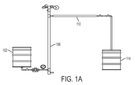
[00038] Referring to FIGS. 1A-1H, a continuous HTC system 100 is shown,
in
accordance with embodiments herein. In an exemplary embodiment, a continuous
HTC
system 100 includes a feed chamber 102, a high pressure pump 104, a vertical
reaction
chamber 106 with an immersion heater 108, a horizontal cooling chamber 110
with heat
exchanger 112, and a receiving tank 114. The feed chamber 102 is fluidly
connected to the
high pressure pump 104, such that material present in the feed chamber 102 can
be
9
CA 03004429 2018-05-04
WO 2017/083544
PCT/US2016/061367
pumped with the high pressure pump 104. The high pressure pump in turn is in
fluid
connection with the vertical reaction chamber 106, such that the material
present can be
pumped into the vertical reaction chamber 106. The vertical reaction chamber
106 is in
fluid connection with the horizontal cooling chamber 110, which, in turn, is
in fluid
connection with the receiving tank 114. In some embodiments, the system also
includes a
thermowell 116 with a plurality of level switches, a pressure relief device
with rupture disc
120, a steam/water injector 122, and back pressure gas release valve 118 in
the headspace
of the vertical reactor. In embodiments, a variety of valves can be employed
between any
and all of the components of the systems described herein.
[00039] The reactor size and slurry feed rate are designed to give
control over
reaction time, and significant electrical heating is provided to allow for
temperature
control in some embodiments. FIG. 1F illustrates a product collection section
of HTC
system 100, in accordance with embodiments herein. FIG. 1G illustrates a
diaphragm
pump with recycle loop of an HTC system whereas FIG. 1H illustrates a double
pipe heat
exchanger which can be used in a continuous HTC system, in accordance with
embodiments herein. Other heat exchanger designs, well known in the community
those
well versed in the art, may be included, such as shell and tube, or plate and
frame.
[00040] Referring to FIG. 11, a schematic of a HTC system and flow there
through
(as indicated by the arrows) is shown, in accordance with embodiments herein.
At 1 wet
biomass is added to the system, for example at a feed chamber. At 2 the wet
biomass is
passed to the pump which passes the wet biomass through an optional recycle
point (the
wet biomass can be recycled back to the feed chamber) and either recycled at 4
or passed
through an optional control valve at 5 and into the reaction chamber
(indicated as PFR in
the figure) at 6. The reacted, for example charred, wet biomass, which can be
liquid, gas
and/or solid is then passed at 7 to a heat exchanger, which cools the solid
and liquid
products. The resultant cooled products are passed at 8 through the paired
solenoid valves
to the collection chamber at 9 as biochar.
[00041] In one particular embodiment, a reactor system is designed for a
5 gal/h
dairy manure treatment. An 85 gal feed tank is charged with fresh manure and
additional
water (to maintain 9:1 water, biomass ratio). A 1 hp drill with a propeller is
used for
continuous mixing of the dairy manure, to avoid the clogging at the discharge
of the tank.
A high pressure slurry pump is inserted to increase the pressure of the feed
from 1 bar to
50 bar (see, for example, FIG. 1B). The pump operates at 5 gal/h. The high
pressure slurry
CA 03004429 2018-05-04
WO 2017/083544
PCT/US2016/061367
enters a 7 ft vertical pipe reactor. A 10 kW immersion heater, inserted from
the bottom of
the vertical reactor to ensure the temperature of the slurry reaches 260 C
(see, for
example, FIG. 1B), and the external surface of the pipe reactor is fitted with
resistance
heaters for extra heating needed for startup. As the slurry is pumped from the
bottom, the
product is pushed to the top into the horizontal section. The reaction time,
or the time it
would take a single particle from the bottom of the reactor to the top is
designed to be 5
minutes. In the headspace above the reactor, there is a back-pressure gas-
release valve,
which releases the process gas periodically (see, for example, FIG. 1E). A
pressure-relief
device along with a rupture disc is inserted at the other end of the headspace
for safety
purposes. There is also a steam/water injection line to clean up the reactor
after a
continuous cycle. The slurry is carbonized along the vertical reactor to
produce gas, liquid
and solid products. The liquid and solid products enter into the horizontal
cooling section
(see, for example, FIG. 1D), where an external chiller reduces the temperature
from 260 C
to50 C, effectively quenching the reactions. The pressure is 50 bar throughout
the reactor
system. At the end of the horizontal cooling system, there are two sequential
gate valves
(2.4 ft apart from each other), controlled in such a way that valves are
open/close
sequentially (similar to a solenoid) so that product exits from 50 bar to 1
bar without
reducing overall pressure of the reactor system. The products are collected in
another 85
gal tank.
[00042] Also disclosed herein is a continuous HTC process for wet biomass
treatment. FIG. 2 provides a piping and instrumentation diagram (P&ID) of an
exemplary
continuous HTC system. Example 1 below describes exemplary process components
and
safety features of an exemplary semi-continuous HTC process. Start up, shut
down, and
emergency operation procedures are also provided below. It is contemplated
that in some
embodiments, a disclosed system operates in a continuous manner, minute to
minute, but
stops periodically, for example, to be recharged. Thus, a disclosed system can
operate
continuously (not needing to be recharged) or semi-continuously (if needing to
stop
periodically, such as for recharging or discharging).
[00043] Methods of using the disclosed HTC systems are also provided. For
example, methods of hydrothermal carbonization of wet biomass as described
herein. In
one example, the method comprises providing a wet biomass mixture to a feed
chamber
wherein the mixture is prepared for processing; applying pressure to the
system; providing
the wet biomass the reaction chamber; heating the wet biomass mixture in the
reaction
11
CA 03004429 2018-05-04
WO 2017/083544
PCT/US2016/061367
chamber so that the wet biomass mixture is carbonized along the reaction
chamber to
produce gas, liquid and solid products; cooling the produced liquid and solid
products in
the cooling chamber; and collecting the produced liquid and solid products in
the receiving
tank coupled to the second end of the cooling chamber, wherein the produced
liquid and
solid products to exit the cooling chamber into the receiving tank without
reducing overall
pressure of the system.
[00044] The following non-limiting examples are provided to illustrate
certain
particular features and/or embodiments. These examples should not be construed
to limit
the disclosure to the particular features or embodiments described.
EXAMPLES
Example 1
Continuous hydrothermal carbonization (HTC) process for dairy manure treatment
[00045] This example provides an exemplary process for continuous HTC for
dairy
manure treatment.
[00046] HTC may operate at temperatures between 180 C and 260 C, and
pressures as high as 50 bar, in which water provides the autogenic pressure
(vapor
pressure), thus precise equipment design with multiple levels of controls to
maintain
personal and operational safety is desirable.
[00047] Pretreatment is performed prior to feeding wet biomass to this
continuous
prototype. It ensures that the ratio of water to solids is appropriate. A
minimum water:
biomass ratio was 10:1 on a mass basis, but for most studies, the ratio was
19:1 (i.e., 5%
solids). To ensure the integrity of the pump and several downstream
components, all solids
are crushed to a small size prior to feeding. Size of particles should be
consistent with
pump and other hardware in the reactor system.
[00048] FV1: The process starts with a feed vessel (FV1), which is a 55
gal plastic
drum with a drain (ID 3/8") at the bottom. First, 150 L of manure slurry (5
wt% 0.074 mm
particle sized solid) is charged into FV1. To ensure a homogeneous mixture and
avoid
solid setting and vessel clogging, a stirring attachment is used. A level
indicator (LI1)
connected with a level transmitter (LT1) provides the liquid level in the FV1.
In case of
low fluid level, the process will be alarmed with low level alarm (LLA), which
terminates
the process operation. A recycle line (stream # 11) terminates in the FV1,
which is the
primary emergency mode of this prototype. For any downstream process failure,
the
12
CA 03004429 2018-05-04
WO 2017/083544
PCT/US2016/061367
emergency mode will be activated to recover any fatal error.
[00049] DP1: Slurry from the FV1 will run through a diaphragm pump (DP1,
Hydracell pump rated for 70 bar pressure with stainless steel housing). The
volumetric
flow rate is normally controlled by adjusting CV1 and to a lesser extent by
adjusting the
pump motor speed. An objective for the pump is to deliver slurry at operating
pressure (7-
50 bar) at room temperature. The pump is factory manufactured and certified.
Slurry ejects
from the pump outlet (high pressure, low temperature) and is split into two
streams
through a tee (3/8" sch. 80 carbon steel) where one stream passes to the
control valve 1
(CV1) in the direction of downstream process and the other stream towards the
back-
pressure valve 1 (BPV 1), returning to FV 1 for flow control and emergency
operation.
Stream 2 pressure will be monitored and recorded to ensure the pump
performance. A
discrepancy of expected pressure signals a need for pump and related fittings
inspection.
The slurry at the stream 2 will then pass through a check valve 1 (Ch V1),
which is to
ensure no reverse flow of the slurry. A flow element (FE 1) will ensure the
desired
flowrate by controlling the opening CV1. The slurry stream that was not
recirculated to
FV1 will flow into the reactor chamber. In case of ChVl failure, the process
will go into
emergency mode, where CV1 is 100 % open. In case of CV1 failure, DP1 will be
shut
down manually.
[00050] RV1: The reactor is a 120" length of 1 1/2" Schedule 80 carbon
steel pipe.
The reactor is divided into two zones although made from a single pipe. The
lower zone is
called the heating zone, and contains an immersion heater (H1) inserted
through a cross at
the base of RV1. Slurry flows upward through this zone, and is heated to
reaction
temperature by an immersion heater (H1, model MTS 1 1/2" NPT screw threaded 15
KW
heater with 316 stainless steel sheath and fitting). The upper zone is the
reaction zone.
[00051] The upper zone of the reactor is the reaction zone and headspace
for gas
products. A 304 stainless steel 1 1/2" NPT screw threaded thermowell is
inserted from the
top of the RV1. Two level gauges float along the thermowell to sense and
indicate the
fluid level in the reactor. The first level element (LE 2) will control the
downstream flow
by controlling the solenoid valve (SV1). Meanwhile, LE 3 is a safety element,
located
above the outlet where only gaseous products should be present in normal
operation. LE 3
triggers emergency mode with the high level alarm (HLA) activation. In the
headspace, a
back pressure valve (BPV 2) is set to bleed gaseous product at a designated
flow rate. In
case of overpressure, the relief valve 1 (RV 1) will depressurize the reactor,
while ensuing
13
CA 03004429 2018-05-04
WO 2017/083544
PCT/US2016/061367
no feed flow from the G1 Vi. Finally, a Buna-N rupture disk (RD 1) will be
inserted at the
top of RV1 for redundant safety. The power to the immersion heater (H1) will
be
controlled by a PID controller reading temperature element 2 (TE 2). The
failure of the
heater will enable the emergency mode, and the content of the reactor is
subsequently
drained manually by the ball valve 1 (BV1) manually. Besides H1, an external
heater (H2,
heating tape, 13.1 W/in2, 3 m long from OMEGA) will be wrapped on the pipe
external
surface to increase heating rate during start-up. H2 will be controlled
manually by
monitoring TE 2 and TE3. Finally, RV 1 will be insulated by heating insulation
blanket
(Durablanket S type). After each run, the reactor will be cleaned by pumping
hot water or
steam through gate valve (GV 1) and BV1.
[00052] HU:A high pressure, hot slurry will exit from the RV 1 by stream
line 4
towards the heat exchanger (HE 1). HE 1 functions to reduce the temperature
from
reaction temperature to 50 C. Slurry coming out from the HE 1 is still
pressurized but low
temperature. Temperature of stream 7 will be controlled by regulating the flow
(CV2) of
the cold stream, itself cooled by a glycol chiller. The failure of HE 1 will
activate
emergency mode.
[00053] PV1: Stream 7 will pass through a solenoid valve (opened/closed)
SV 1,
which is automatically controlled by monitoring LE 2 to maintain a designated
height in
RV1. Now, slurry passed from SV 1 will then go towards 5V2. SV1 and 5V2 are
synchronized in such a way that when SV1 is open, 5V2 is closed. Slurry will
experience
volume expansion and is trapped into stream 8 when SV1 is closed, between the
two
valves. After SV1 is closed, 5V2 will be opened and slurry is ejected into
stream 9. Stream
9 is open to product vessel 1 (PV1), which is a 55 gal plastic vessel at
ambient pressure
and temperature. A 320 mesh stainless steel sieve will filter the solid from
liquid. Another
level element (LE 4) will be introduced to measure the liquid level in the PV
1.
[00054] Emergency Mode: The computer will continuously monitor pressure
and
temperature throughout the apparatus. Emergency response is triggered by high
pressure
or high level alarms, as described above. Upon detection of a pressure
discrepancy, the
computer will immediately open CV1, close GLV1, and send an alarm to the
operator to
turn off the pump. This will cause recirculation process fluid back to FV1.
Power to the
two heaters will be turned down to 0%.
[00055] Troubleshooting will involve several strategies. The pressure
transducer
data will be examined to try to find the location of the fault. The reactor
could be run with
14
CA 03004429 2018-05-04
WO 2017/083544
PCT/US2016/061367
cold, pressurized water at the operator's discretion. Once the fault is
corrected, emergency
mode operation is overridden by restarting the computer program.
[00056] Table 1: List and specification of symbols in FIG. 2.
Symbol Device Specification
FV 1 Feed vessel no 1 55 gal metal drum with mixer drill (1 hp motor)
RV 1 Reaction vessel 1 1 1/2 in schedule 80 CS 304 pipe with 1 1/2 in
NPT
threading length = 120 in
PV 1 Product vessel 1 55 gal metal drum with a SS 320 mesh sieve
DP 1 Diaphragm pump 1
CV 1 Control valve 1 _ ______________________________________
High pressure room temperature 3/8 in brass valve
Ch V 1 Check valve 1 3/8 in brass high pressure room temperature
BV 1 Ball valve 1 1/2 in high temp high pressure Swagelok ball valve
RV 1 Relief valve 1 1/4 in SS 304 relief valve rated max 1000 psi
BPV 1 Back pressure valve 1 3/8 in back pressure valve SS 304
GV 1 Gate valve 1 1/4 in high temp high pressure gate valve SS 316
CV 2 Control valve 1 High pressure room temperature 1/8 in brass valve
GV 2 Gate valve 2 1/4 in brass low pressure room temperature
SV 1 Solenoid valve 1 High pressure low temperature 1/4 in solenoid
valve
SV 2 Solenoid valve 1 High pressure low temperature 1/4 in solenoid
valve
RD 1 Rupture disk 1
H1 Heater 1 MTS 2 type 15 KW 2in NPT screw fitting SS
immersion heater
H 2 Heater 2 Heating tape 13.1 W/in2 from Omega
LI Level indicator SS 304 float type
LT Level transmitter
HLA High level alarm
LLA Low level alarm
CA 03004429 2018-05-04
WO 2017/083544
PCT/US2016/061367
LC Level controller
LY Level relay
FE Flow element Flow meter
FT Flow transmitter
FC Flow controller
TE Temperature element J type thermocouple inserted into the SS 304
thermowell
TT Temperature transmit
TC Temperature PID controller
controller
PR Pressure record
PC Pressure control
Start Procedure
1. Turn on the main breaker (I1B-HTC) from the electric panel. This will
ensure power
on computer, FV1 mixer motor, DP1 motor, H1, H2, LE2, LE3, glycol chiller of
HE1,
SV1, and SV2.
2. Turn on computer and select Labview. The operation mode should be MANUAL.
3. Make sure CV], Ch V1, BV1, BPV2, RV1, RD1, GV1, Si, and S2 are fully
closed.
4. Open GV1 slowly until the LE2 low alarm. Notice that there is water
coming out from
5V2. This makes sure the reactor is two third filled with water.
5. Fully close GV1.
6. Turn on H1 and H2. This will increase the reactor temperature. Make sure
the PID
controllers are set at reaction temperature. It takes approximately 1 hour to
reach the
reactor temperature into reaction temperature.
7. Fill the FV1 with feed. Note: the feed will be >90% water and maximum
particle size
of 701.t.
8. Switch on the mud mixer in the FV1. This will keep the feed homogeneous
throughout
the operation.
16
CA 03004429 2018-05-04
WO 2017/083544
PCT/US2016/061367
9. Turn on the DP1 motor, keeping the CV1 fully closed. This will cause
100% recycle of
the feed from BPV1.
10. Turn on FEL when computer screen shows SAFE TO FEED. If the reactor
reaches
reaction temperature (by reading TE2 and PI1), the signal goes to the computer
and
SAFE TO FEED light will be ON.
11. Turn on the glycol chiller at HEL This will reduce the temperature of the
stream 7
from reaction temperature to approximately 50 C. The temperature can be seen
by
TE4 in the computer screen.
12. Change the operation mode from MANUAL to AUTO. This will read the FE1 and
adjust CV1.
Once the CV1 open, the product is observed at PV1 in approximately 5 minutes.
During operation, an operator may record the reading of TE1, TE2, TE4, FE1,
and PI1
every five minutes. Also, the operator may observe the BPV2 gas emission every
five
minutes as well.
Shutdown Procedure*
1. Switch the program from AUTO to MANUAL.
2. Turn offH1 and H2.
3. Turn off the mud mixer at FV1.
4. Switch stream 1 from FV1 to Washing Water Vessel.
5. Switch process stream 9 from PV1 to drain.
6. Increase the FE1 to 1 gpm.
7. Run the system until TE1 and TE3 show ¨50 C.
8. Fully close the FE]. The feed will 100% recycle from BPV1.
9. Turn off the motor of DP1.
10. Turn off the glycol chiller ofHE].
11. Open BV1 to drain the remaining water in the RV1 and RV2. Close BV1 and
Open
GV1 until low alarm of LE2.
12. Follow step 8 of shutdown procedure.
13. Turn off the Main Breaker.
17
CA 03004429 2018-05-04
WO 2017/083544
PCT/US2016/061367
[00057] Water vapor pressure:
[00058] The Antoine equation is a vapor pressure equation and describes
the
relationship between vapor pressure and temperature for pure components.
log top= A ¨ ____________________________
C T
[00059] where, p is the vapor pressure, T is temperature and A, B and C
are
component-specific constants.
[00060] For water, the constants A, B, and C 8.14, 1810.94, and 244.485,
respectively for the temperature range 99-374 C. By computing these, FIG. 3
can be
generated for vapor pressure of water. Pressure is increasing with the
increase of
temperature, which can also be interpreted that if water is heated in a closed
container, it
will generate the corresponding pressure as indicated by FIG. 3. This
relationship can be
used for estimating reactor pressure at any reactor temperature.
[00061] Wet torrefaction or HTC is a thermochemical process to treat
biomass,
waste, or any organic feedstock and upgrade into high value products like
solid biocoal
(hydrochar, a lignite type fuel), liquid fertilizer, and platform chemicals
(e.g., HMF,
furfural, levuglocosan).
[00062] The process involves hot compressed water being used as a solvent
and
catalyst. As shown in the FIG. 3, liquid hot water around 180-260 C can exert
7-50 bars
of pressure. Now, the properties of subcritical water (liquid water in the
temperature range
100-374 C) are very different from those of water at ambient condition (25 C,
1 atm).
Subcritical water in the temperature 180-260 C has maximum ionic product, in
other
words, acts as a mild acid and base and thus catalyzes the reaction. When
biomass is
treated with subcritical water, biomass fiber components (hemicellulose,
cellulose, lignin
etc.) are degraded to some extent, based on process severity. Numerous
chemical reactions
(hydrolysis, dehydration, decarboxylation, condensation, polymerization,
aromatization
etc.) occur simultaneously in the liquid media. FIGS. 4 and 8 show exemplary
products
from a HTC reaction. Now, as a result of these series of reactions, the solid
biomass is
converted chemically and physically, becomes hydrophobic and with increased
fuel value,
while, liquid product contains polar and nonpolar chemicals. There is also
production of
gases comprised almost entirely of CO2. Approximately 1 kg of biomass is
converted to
18
CA 03004429 2018-05-04
WO 2017/083544
PCT/US2016/061367
0.6 kg hydrochar, 0.15 kg of CO2, 0.2 kg of organic acids and sugars, and
about 0.05 kg of
water. The production of CO2 and water generally increases with increasing
reactor
temperature, primarily at the expense of solid hydrochar.
[00063] FIGS. 5A-5D provide some of the primary components in an
exemplary
continuous HTC system. For clarity, the controlling devices and systems are
omitted from
FIGS. 5A-5D. A complete front view of the semi-continuous prototype
(simplified
version) is shown in FIG. 5A. The FV 1 is located in the left side of the
figure with the
DP1 underneath, while the RV1 can be found in the right side figure. The pump
(DP1)
unit, with the stream lines 1, 10, and 2 is shown in FIG. 5B. The recycle line
is shown in
FIG. 5C. Finally the headspace unit with BPV1, RV1, and GV1 assembly can be
found in
FIG. 5D.
Example 2
Continuous hydrothermal carbonization (HTC) process for dairy manure treatment
[00064] This example provides an exemplary process for continuous HTC for
dairy
manure treatment.
[00065] As stated previously, HTC or wet torrefaction is a treatment
process which
converts moist feedstocks into homogenized, carbon rich, and energy dense
solid fuel,
called hydrochar. One of the main advantages of HTC compared to other
thermochemical
treatment processes is the use of residual moisture as reaction medium and
catalyst. Thus,
there is no need for expensive drying prior to HTC treatment. Thermodynamic
properties
of water change greatly in the subcritical region from 180-280 C, and as a
result,
subcritical water behaves as a non-polar solvent and mild acid and base
catalyst
simultaneously. Biomass, when subjected to HTC, releases oxygen-containing
volatiles
and hydrochar becomes highly hydrophobic. FIG. 7 provides a schematic
illustrating
hydrothermal carbonization complex reaction mechanism and FIG. 8 illustrates
products
using a disclosed HTC system.
[00066] Although HTC offers a relatively simple and straightforward
solution to
process diverse biomass feedstocks, the requirements of high pressure and high
temperature make the process complex and costly to design and operate. The
batch
process requires loading, heating, cooling, and unloading in sequence for each
batch, thus,
heat recovery is compromised and scale-up is not feasible. Meanwhile, a
continuous
19
CA 03004429 2018-05-04
WO 2017/083544
PCT/US2016/061367
process offers a relatively smaller footprint, higher energy recovery hence
efficiency and
economics of scale.
[00067] A bench-scale continuous HTC reactor system was designed as
illustrated
in FIG. 1A-1H, commissioned, and operated with various feedstocks including
glucose,
cellulose, and dairy manure. FIG. 11 is a schematic illustrating process
simulation using a
continuous HTC reactor. FIG. 1J is an image of a Lab VIEW interface of a
continuous
HTC reactor. The throughput of the reactor system was maintained at 5 gal/h,
while the
reaction time was maintained at 5 min. The maximum temperature and pressure
were
tested for this study was 230 C and 25 bar. Both solid and liquid product
were tested for
their physico-chemical properties and compared with the corresponding products
from
batch process produced in a Parr reactor. HTC temperature and pressure were
stable
during operation and products are relatively similar to batch process.
[00068] Process data produced for a sample HTC run on a disclosed
continuous
HTC system as illustrated in FIGS. 1A-1I is presented in FIGS. 6A-6D. Model
biomass
(glucose) was hydrothermally carbonized in a reactor system as illustrated in
FIGS. 1A-1I
for this run. The temperature around 210 C achieved here and pressure around
500 psig.
The flow rate was maintaining around 0.1-0.2 gpm (gallon per minute) after the
start-up
stage. Data were acquired for 3600 s (1 hour), which included start-up,
heating, steady-
state, and cool-down period.
[00069] FIG. 6A is the temperature profile of the tested reactor system.
Two
different temperatures were recorded in this run, (i) inside of the reactor,
and (ii) outlet
temperature after the heat exchanger. The first one was denoted as T4 and
second one as
T5. Inside temperatures of the reactor were measured by thermocouples inserted
into a
thermowell along with level switches. The thermocouple reading in the reaction
zone was
denoted here as T4. As seen from the FIG. 6A, the reactor temperature
increased with the
increase of time until 1800 s, when the heater power was turned off The
highest
temperature was reached around 210 C. After the heating period, T4
temperature was
decreased with time.
[00070] A heat exchanger was designed and fabricated for this reactor
system. The
heat exchanger used 70-30 vol% water-antifreeze as coolant to cool-down the
product
temperature co-currently. T5 was the temperature after the heat exchanger. The
temperature was below the reactor temperature all the time. In fact, it never
reached more
than 90 C, so water was not boiling when discharged from the reactor. The
maximum
CA 03004429 2018-05-04
WO 2017/083544
PCT/US2016/061367
temperature at the T5 was recorded around 30 minutes process time, where the
reactor
temperature had reached maximum. Like the reactor temperature (T4), product
temperature (T5) was decreasing with time after the heater was turned off
[00071] FIG. 6B shows the process pressure in various regions of the
system for the
same run. The inlet pressure, produced by the pump, was denoted as Pl, while
the pressure
recorded between the solenoid valves was denoted as P2. The process pressure
was
recorded as high as 500 psig during the start-up period, afterwards, it
gradually increased
with time until 30 minutes. During the cooling period (shut-down) the pressure
was
atmospheric (0 psig) as both the solenoid valves are open. Now, pressure P2
had some
cyclic ups and downs, as when the pressure P2 = Pl, first solenoid valve was
open and
that caused pressure drop. The pressure P2 again built up until it reached the
same as Pl.
[00072] FIG. 6C shows the heater power and flow rate with time. A 10 KW
immersion heater was used to heat the reactor content. Both heater power and
flow rate
can be controlled both manually and automatically. The heater power was 100 %
for the
start-up period (until 15 minutes). After that, it adjusted manually and
finally the heater
power was remained steady around 90% from 1400-1800 s. The heater was turned
off
afterwards. The flow rate varied with time. During the start-up period, the
flow rate was
high to fill the reactor, and maintained around 0.1-0.2 gpm afterwards before
the flow was
stopped.
[00073] The resulting samples were chemically analyzed with HPLC. Samples
from
feed, start-up (different temperature), and steady state were collected and
analyzed
quantitatively by HPLC. The data are presented in Table 3 below. The feed
contained only
glucose and the concentration was around 17.5 g L-1. The first sample was
taken at around
140 C, which contained small fraction of acetic, formic, and levulinic acids
beside
glucose. It is possible that some glucose, especially adjacent to the heater
surface, may
have been reacted to these products. At 195 C, dehydration products of
glucose like HMF
and organic acids were observed. 1,3 dihydroxyacetone and glycoldehyde dimer
both are
dehydration products or HMF. It indicates that glucose first dehydrated to HMF
which
further dehydrated to these products in the route of producing hydrochar.
Early steady
state (210 C) and steady state (220 C for 15 minutes) similar HMF was found.
Concentrations of organic acids were increasing during the steady state.
Table 3.
21
CA 03004429 2018-05-04
WO 2017/083544 PCT/US2016/061367
-c-t
EP(
. E
,,,4
k...., 0 0
'Ft= . -c-,,, .,,.-4
4-4 -0
. -
,., ,.., cn 4., .0 .2 =,(A) .2
K 8 f) 73' 73' i 73'73' Tzt' 73' 8 7,z,' *g
ct 2 ct b ct ct 6
H
c)
-,,s ,
. ,
4-i S
,--i
0
0 N N kr) Cr)
(r)
71- (n kr)
1--1
.:4
ct cc: C.) kr) 0 71- 71- C4
01 CD CD
0 0
0 C)t)
(:)C ,--i Cr) N ,--i ,--i
, ,
7:$ A-,"' 0 N (') 0 kr) kr) N 01 S
ct cz ,--i 0 71- c) C4 0 N S kr) Cr) 0
C4
C4
C+A u)
51 ct N 0 0 `n 71- S
¨ -4-= (-1 kr) 4 N
01
C+A u)
[00074] In view of the many possible embodiments to which the principles
of the
disclosed invention may be applied, it should be recognized that the
illustrated
embodiments are only preferred examples of the invention and should not be
taken as
limiting the scope of the invention. Rather, the scope of the invention is
defined by the
following claims. We therefore claim as our invention all that comes within
the scope and
spirit of these claims.
22