Note: Descriptions are shown in the official language in which they were submitted.
1
Vehicle rear body structure and method for manufacturing thereof
The present invention relates to a vehicle rear body structure.
Conventionally, the rear body structure of a vehicle includes a series of
structures, located
at the rear of the fuel tank, which are intended to absorb impact energy by
deforming in response
to an impact at the rear of the vehicle, and thus protect the fuel tank in the
case of such an impact.
These structures include a rear bumper beam and crash boxes, located between
the rear ends
of the rear rails of the rear body structure and the bumper beam.
The rear rails are located in front of the crash boxes. They conventionally
have a
resistance that is greater than that of the bumper beam and of the crash boxes
and are intended
for transferring the impact forces to the structural elements of the vehicle
body. A front portion of
the rear rails extends alongside the fuel tank of the vehicle, which is
usually located at the rear
end of the vehicle, in front of the wheel casings.
It appears that, in the case of high speed impacts on the rear of the vehicle,
the
conventional shock absorbing structures mentioned above may not sufficiently
absorb the impact
energy and the impact may result in a crushing of the rear rail(s). Such an
uncontrolled crushing
may result in an intrusion of some elements of the rear body structure into
the gas tank, thus
causing damage to the fuel tank, which might lead to spilling of the fuel and
may ultimately result
in an explosion of the vehicle. Therefore, damage to the fuel tank should be
avoided, even in the
case of high speed impacts.
One purpose of the invention is to provide a vehicle rear body structure which
provides for
an improved crashworthiness in the case of a rear impact on the vehicle, and
in particular which
provides for an improved protection of the fuel tank in the event of such an
impact.
The invention also relates to a vehicle body comprising the vehicle rear body
structure as
defined above.
In another aspect, the invention relates to a vehicle rear body structure
comprising a rear rail
extending in a longitudinal direction and a rear bumper beam, extending
transversely to the
longitudinal direction, the rear rail having a rear end and a front end,
spaced apart along the
longitudinal direction, the rear end being connected to the rear bumper beam
and the rear rail
extending towards the front of the vehicle from its rear end,
wherein the rear rail comprises at least a front portion, an intermediate
portion and a rear portion,
the front portion being intended for extending alongside a fuel tank of the
vehicle, the resistance
to plastic deformation of the front portion being greater than the resistance
to plastic deformation
Date Recue/Date Received 2022-03-24
la
of the intermediate portion, which is itself greater than the resistance to
plastic deformation of the
rear portion, and
wherein the vehicle rear body structure further comprises a guide structure
intended for guiding
the deformation of the rear rail so as to prevent a deformation thereof in a
direction perpendicular
to the longitudinal direction.
Other features and advantages of the invention will be better understood from
reading of
the following description, given with reference to the appended drawings, in
which:
- figure 1 is a perspective bottom view of a portion of a vehicle rear body
structure
according to a particular embodiment;
Date Recue/Date Received 2022-03-24
CA 03004454 2018-05-04
WO 2017/098306 PCT/IB2015/059487
2
- figure 2 is a perspective view of a portion of a vehicle rear body
structure according
to a particular embodiment; and
- figure 3 is a perspective view of a rear rail of figure 2.
In the following description, the terms inner, outer, front, rear,
transversal,
longitudinal, vertical, horizontal, top and bottom are construed with
reference to the usual
orientation of the illustrated elements, parts or structures when assembled on
a vehicle
structure, the vehicle lying on a horizontal plane.
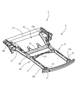
A vehicle rear body structure 2 according to an embodiment is illustrated on
Figure
1. The vehicle front body structure 2 may be a rear body structure of any kind
of four
wheel vehicle, in particular a front body structure of a unitized body.
The vehicle front body structure 2 comprises a frame assembly 4. The frame
assembly 4 comprises two rear rails 10, 12 and a rear bumper beam 21.
Each rear rail 10, 12 extends substantially along the longitudinal direction
of the
vehicle. The rear rail 10 extends on one side of the vehicle in a front-rear
direction of the
vehicle body. It comprises a rear end 10a and a front end 10b. Similarly, the
rear rail 12
comprises a rear end 12a and a front end 12b.
The rear bumper beam 21 extends substantially transversely to the longitudinal
direction. It extends at the rear of the rear rails 10, 12. The rear end 10a,
12a of each rear
rail 10, 12 is connected to the rear bumper beam 21, in particular through
crash boxes 31,
33. More particularly, the rear bumper beam 21 bears longitudinally on the
rear ends 10a,
12a of the rear rails 10, 12, in particular through said crash boxes 31, 33.
The front end 10b, 12b of each rear rail 10, 12 is connected to a structural
element
of the vehicle's body.
In the example shown in Figure 1, the frame assembly 4 further comprises a
rear
intermediate transversal beam 23, a front intermediate transversal beam 25 and
a front
transversal beam 27.
The front transversal beam 27 extends between the front ends 10b, 12b of the
rear
rails 10, 12. It is intended for extending at the front of the wheel casings
of the vehicle.
The rear and front intermediate transversal beams 23, 25 extend between the
rear
transversal beam 21 and the front transversal beam 27. They are connected to
the rear
rails 10, 12 at their lateral ends. The rear and front intermediate
transversal beams 23, 25
are located at the wheel casings of the vehicle and reinforce the vehicle rear
body in the
area.
The front intermediate transversal beam 25, the front transversal beam 27 and
the
rear rails 10, 12 delimit among themselves a frame 35 intended for receiving
the fuel tank
CA 03004454 2018-05-04
WO 2017/098306 PCT/IB2015/059487
3
of the vehicle. The fuel tank has not been shown in the drawings in order not
to overly
complicate the drawings.
The rear rails 10, 12 are provided as pairs in left-right symmetry with
respect to the
lateral direction. In the following, the description will be made with
reference to the right
rear rail 10, on the understanding that the same description applies to the
left rear rail 12.
As can be seen on Figures 2 and 3, the rear rail 10 is substantially U-shaped.
It
comprises an outer flank 34, oriented towards the exterior of the vehicle, and
an inner
flank 35 parallel to the outer flank 34, oriented towards the interior of the
vehicle. The rear
rail 10 further comprises a bottom 36 oriented towards the bottom of the
vehicle, the
bottom being substantially orthogonal to the inner and outer flanks 34, 35.
The U-shaped
rear rail 10 opens upwardly.
The rear rail 10 extends in a substantially longitudinal direction. It
comprises, from
the front end 10b to the rear end 10a, a front portion 37, an intermediate
portion 39 and a
rear portion 41. The intermediate portion 39 extends the front portion 37
rearwards, and is
itself extended rearwards by the rear portion 41. The front portion 37,
intermediate portion
39 and rear portion 41 are adjacent to one another along the longitudinal
direction.
In this example, the front end of the intermediate portion 39 is connected
directly to
the rear end of the front portion 37. The rear end of the intermediate portion
39 is
connected directly to the front end of the rear portion 41.
The front portion 37 is intended for extending longitudinally alongside the
fuel tank of
the vehicle. Its front end forms the front end 10b of the rear rail 10. In the
example shown
in Figure 1, the front portion 37 extends between the front transversal beam
27 and the
front intermediate transversal beam 25. The front portion 37 is curved in a
longitudinal
plane extending substantially horizontally.
The intermediate portion 39 is substantially straight. It extends between the
front
portion 37 and the rear portion 41 along the longitudinal direction. In the
example shown
in Figure 1, the intermediate portion 39 extends towards the rear of the
vehicle rear body
structure from the front intermediate transversal beam 25. In this example,
the back
intermediate transversal beam 27 extends transversely between the intermediate
portions
39 of the rear rails 10, 12.
The rear portion 41 is substantially straight. The rear end of the rear
portion 41 forms
the rear end 10a of the rear rail 10.
Each of the rear portion 41, the intermediate portion 39 and the front portion
37 is U-
shaped and comprises an inner wall, an outer wall and a bottom, which each
form a
section of the inner wall 35, the outer wall 34 and the bottom 36 of the rear
rail 10.
CA 03004454 2018-05-04
WO 2017/098306 PCT/IB2015/059487
4
The rear rail 10 is made of steel, for instance dual-phase steel or press
hardened
boron steel.
According to the invention, the front portion 37, the intermediate portion 39
and the
rear portion 41 each have a different resistance to plastic deformation, the
resistance to
plastic deformation increasing from the rear end 10a of the rear rail 10 to
the front end 10b
of the rear rail 10.
More particularly, the resistance to plastic deformation of the front portion
37 is
greater than the resistance to plastic deformation of the intermediate portion
39, which, in
turn is greater than the resistance to plastic deformation of the rear portion
41.
The resistance to plastic deformation increases with increasing wall thickness
t of
the considered rear rail portion, as well as with increasing yield strength of
the material
forming said rear rail portion.
More particularly, the resistance to plastic deformation of each portion of
the rear rail
10 may be characterized by the product P of the square of wall thickness t of
the
considered portion of the rear rail 10 by the yield strength Re of said
portion.
Advantageously, this product P increases from the rear end 10a to the front
end 10b
of the rear rail 10.
More particularly, the product P for the front portion 37 is greater than the
product P
of the intermediate portion 39 and the product P is greater than the product P
of the rear
portion 41. In other words, for each portion of the rear rail 10, the
thickness t and the yield
strength Re are chosen such that the product P increases from one section to
the next
from the rear to the front of the rear rail 10.
According to one particular embodiment, the yield strength Ref of the material
forming the front portion 37 is greater than the yield strength Re, of the
material forming
the intermediate portion 39, which in turn, is greater than the yield strength
Re, of the
material forming the rear portion 41. Thus, Ref > > Rer.
For example, the yield strength Rer of the steel forming the rear portion 41
may be
comprised between 200 and 700 MPa, while the yield strength Re, of the steel
forming the
intermediate section 39 is comprised between 300 and 1300 MPa and the yield
strength
Ref of the steel forming the front portion 37 is comprised between 400 and
1500 MPa.
In particular, the yield strength Ref of the material forming the front
portion 37 is
greater by at least 100 MPa than the yield strength of the material forming
the rear portion
41.
As an alternative, the wall thickness t of the rear rail 10 increases from the
rear end
10a to the front end 10b.
CA 03004454 2018-05-04
WO 2017/098306 PCT/IB2015/059487
More particularly, the wall thickness tf of the front portion 37 is greater
than the wall
thickness t, of the intermediate portion 39, which is itself greater than the
wall thickness tr
of the rear portion 41. In other words, tf > t > tr.
For example, the thickness tf of the wall of the front portion 37 may be
comprised
5 between 1,4 and 3 mm, while the thickness tr of the wall of the
intermediate portion 39 is
comprised between 1,4 and 3 mm and the thickness t of the wall of the rear
portion 41 is
comprised between 1 and 2 mm.
In particular, the wall thickness tf of the front portion 37 is greater by at
least 0,4 mm
than the wall thickness tr of the rear portion 41.
Advantageously, both the yield strength Re and the wall thickness t of the
rear rail 10
increase from the rear end 10a to the front end 10b of the rear rail 10. More
particularly,
the following relationships apply: tf > t, > tr and Ref > Re, > Rer.
This gradual increase in the resistance to plastic deformation along the
length of the
rear rail 10 from the rear portion 41 to the front portion 37 results in an
improved
crashworthiness of the vehicle in the event of an impact at the rear of the
vehicle.
Indeed, in the case of such an impact of sufficient strength, the rear portion
41 of the
rear rail 10 will deform and absorb a considerable portion of the impact
energy. Since the
resistance to plastic deformation of the front portion 37 is greater than that
of the rear
portion 41, it will stay substantially intact as a result of the impact, thus
preventing an
intrusion of other components of the rear body structure into the fuel tank,
alongside which
the front portion 37 extends. This feature is important in order to avoid
damage to the fuel
tank due to an impact and fuel spillage possibly resulting therefrom, as well
as to reduce
the risk of explosion resulting from an impact at the rear of the vehicle. The
intermediate
portion 39, which has a resistance to plastic deformation that is intermediate
between
those of the front portion 37 and of the rear portion 41, deforms only once
the rear portion
41 has been deformed, and, by deforming, absorbs impact energy and protects
the front
portion 37. It helps manage the plastic hinge between the rear portion 41 and
the front
portion 37 by keeping the front and intermediate portions 37, 39 of the rear
rail 10 intact
while the end section is absorbing most of the crash energy by deforming at
the earliest
crash phase and avoiding unwanted material failure risk when the local plastic
hinge
occurs in a later phase of crash.
According to one embodiment, each of the front, rear and intermediate portions
37,
41, 39 has the same yield strength along its entire length.
For example, the rear portion 41 is a press-hardened steel part having, after
press-
hardening, a yield strength Re comprised between 360 and 400 MPa. It is more
particularly made of a press-hardenable steel having a carbon content
comprised between
CA 03004454 2018-05-04
WO 2017/098306 PCT/IB2015/059487
6
0,04 wt.% and 0,1 wt.% and a manganese content comprised between 0,3 wt.% and
2,0
wt.%. Even more particularly, the steel composition of the front section 60
comprises in %
weight: 0,04 % C 5 0,1%, 0,3% 5 Mn 2,0%, Si < 0,3%, Ti 0,08%, 0,015 Nb
0,10%, Cu, Ni, Cr, Mo
0,1%, the remainder being iron and unavoidable impurities
resulting from the elaboration. This rear portion 41 advantageously has a wall
thickness of
about 1,6 mm.
The rear portion 41 may also have a wall thickness of about 1,4 mm and be a
press-
hardened steel part having, after press hardening, a yield strength Re
comprised between
700 and 950 MPa. More particularly, the rear portion 41 is made of a press-
hardenable
steel having a carbon content comprised between 0,06 wt.% and 0,1 wt.% and a
manganese content comprised between 1,4 wt.% and 1,9 wt.%. Even more
particularly,
the steel composition of the rear portion 41 may further comprise Nb, Ti, B as
alloying
elements.
The front portion 37 has a wall thickness of about 1,7 mm. It is a press-
hardened
steel part having, after press hardening, a yield strength Re comprised
between 950 and
1200 MPa. More particularly, it is made of a press-hardenable steel having a
carbon
content comprised between 0,20 wt.% and 0,25 wt.% and a manganese content
comprised between 1,1 wt.% and 1,4 wt.%. Even more particularly, the steel
composition
of the front portion 37 comprises in % weight: 0.20% C 0.25%, 1.1% Mn 1.4%,
0.15% Si 0.35%, Cr 0.30%, 0.020% Ti 0.060%, 0.020% Al 0.060%, S
0.005%, P 0.025%, 0.002% B 0.004%, the remainder being iron and unavoidable
impurities resulting from the elaboration.
The front portion 37 may also have a wall thickness of about 1,6 mm and be
made of
a press-hardened steel part having, after press hardening, a yield strength Re
greater than
1260 MPa. More particularly, the steel composition comprises for example, in %
weight:
0.24% C 0.38%, 0.40% Mn 3%, 0.10% Si 0.70%, 0.015% Al 0.070%, Cr
2%, 0.25% Ni 2%, 0.015% Ti 0.10%, Nb 0.060%, 0.0005% 5
0.0040%,
0.003% N 0.010%, S
0,005%, P 0,025%, %, the remainder being iron and
unavoidable impurities resulting from the elaboration.
The intermediate portion 39 has a wall thickness of about 1,7 mm and be a
press-
hardened steel part having, after press hardening, a yield strength Re
comprised between
700 and 950 MPa. More particularly, the intermediate portion 39 is made of a
press-
hardenable steel having a carbon content comprised between 0,06 wt.% and 0,1
wt.%
and a manganese content comprised between 1,4 wt.% and 1,9 wt.%. Even more
particularly, the steel composition of the intermediate portion 39 may further
comprise Nb,
Ti, B as alloying elements.
CA 03004454 2018-05-04
WO 2017/098306 PCT/IB2015/059487
7
According to a second example of the rear rail 10, at least two portions among
the
portions 37, 39, 41 of the rear rail 10 may have the same thickness and the
same
composition, but different yield strengths, the difference in yield strength
being obtained
by subjecting the different portions to a different heat treatment.
For example, the front portion 37 and the intermediate portion 39 have a same
thickness of 1,7 mm and the same composition. More particularly, the steel
composition
of the front portion 37 and the intermediate portion 39 comprises in (3/0
weight: 0.20% C
0.25%, 1.1% Mn 1.4%, 0.15% Si 0.35%, Cr 0.30%, 0.020% Ti 0.060%,
0.020% Al 0.060%, S 0.005%, P 0.025%, 0.002% B 0.004%, the remainder
being iron and unavoidable impurities resulting from the elaboration. However,
the front
portion 37 has a yield strength Re comprised between 950 and 1200 MPa, while
the
intermediate part 39 has a yield strength between 700 and 950 MPa.
As shown in Figure 3, the rear rail 10 may comprise, in its rear portion 41,
crumple
zones 47 to allow the rear rail 10 to controllably deform during an impact. In
this
embodiment, the crumple zones 47 are formed only in a rear area of the rear
portion 41,
and particularly in the rear half of the rear portion 41.
The crumple zones may include, for example, apertures or cavities or ribs
formed on
the walls of the rear portion 41. In the embodiment shown in Figure 3, the
crumples zones
47 are formed by ribs formed in a bottom of the rear portion 41. The ribs
extend
transversely to the longitudinal direction, i.e. substantially vertically.
They are substantially
parallel to one another. In this example they are spaced regularly along the
longitudinal
direction and present a uniform width along the longitudinal direction. Each
rib extends
from the one lateral side to the other of the rear portion 41 of the rear rail
1 O.
In this example, the intermediate portion 39 and the front portion 37 do not
comprise
any crumple zones.
In the example shown in figure 2, the cross-sectional areas of the rear
portion 41
and of the intermediate portion 39 are substantially constant. The cross-
sectional area of
the front portion 37 increases from its rear end to its front end. The cross-
sectional area is
taken in a transverse plane normal to the longitudinal direction. This feature
also
contributes to increasing the resistance to deformation of the front portion
37.
As can be seen on Figure 2, the vehicle rear body structure 2 further
comprises, for
each of the rear rails 10, 12, a guide structure 51 configured for guiding the
deformation of
the corresponding rear rail 10, 12 during an impact at the rear of the
vehicle. In particular,
this guide structure 51 is configured for preventing a deformation of the rear
rail 10, 12
along a direction perpendicular to the longitudinal direction, and more
particularly along
the vertical direction. The guide structure 51 is in particular configured for
preventing part
CA 03004454 2018-05-04
WO 2017/098306 PCT/IB2015/059487
8
of the rear rail 10, 12 from moving upwards when subjected to impact forces
along the
longitudinal direction. The guide structure 51 is therefore configured for
retaining the rear
rail 10, 12 against an upwards deformation when subjected to impact forces
along the
longitudinal direction which would result in lower energy absorption by the
rear portion 41
and more deformation of the front section 37 causing higher unwanted intrusion
in the fuel
tank area. The guide rail 10, 12 therefore deforms mainly along the
longitudinal direction
as a result of such impact forces.
For this purpose, each guide structure 51 comprises at least two legs 53
bearing
upon the rear rail 10, 12 in bearing areas which are spaced apart along the
longitudinal
direction. The legs 53 extend along a direction substantially perpendicular to
the
longitudinal direction, and more particularly vertically. They extend above
the rear rail 10,
12.
In the example shown in Figure 2, the legs 53 have a bottom end and a top end.
The
bottom end of each leg 53 bears on the bottom 36 of the U-shaped rear rail 10.
The legs
53 extend upwards from the rear rail 10 towards an upper structure of the
vehicle body
(not shown in the drawings), and in particular towards a floor element,
extending
transversely substantially between the wheel casings.
The top ends of the legs 53 are, in the example shown in Figure 2, connected
to
each other through a connection element 55.
At its top end, the guide structure 51 is attached to said upper structure of
the
vehicle body, and in particular to the rear wheel casings and the rear floor
of the vehicle
body.
The bottom ends of the legs 53 are inserted into the U-shaped rear rail 10 so
as to
bear on the bottom 36 thereof and be located between the outer and inner
flanges 34, 35.
The legs 53 are further fixed to the rear rail 10 by any adapted fixing means.
In the example shown in Figure 2, the guide structure 51 extends across the
junction
between the intermediate portion 39 and the front portion 37 so as to avoid
any upwards
deformation of the rear rail 10 in this area. More particularly, a front leg
53 of the guide
structure 51 bears on the front portion 37 of the rear rail 10, while a back
leg 53 of the
guide structure 51 bears on the front portion 37 of the rear rail 10.
The positions of those legs 53 are highly limited to maximize the luggage
compartment area.
From a crash management and car body torsional stiffness point of view, a
connection of the legs 53 in the intermediate portion 39 of the rear rails 10,
12 ensures
the highest possible energy absorption in high speed rear crash test and
highest possible
torsional stiffness.
CA 03004454 2018-05-04
WO 2017/098306 PCT/IB2015/059487
9
At least two adjacent portions 37, 39, 41 of the rear rail 10 are connected to
each
other through a weld. According to one embodiment, all three portions 37, 39,
41 of the
rear rail 10 are connected to each other through a weld.
Advantageously, the rear rail 10 is manufactured from a corresponding tailor
welded
blank, the tailor welded blank being obtained by welding, and in particular
laser welding, of
at least as many different blanks as there are portions having different
compositions or
thicknesses in the rear rail 10, 12, each of these blanks having a thickness
and/or a
composition depending on the desired properties of the corresponding rear rail
portion.
For example, the tailor welded blank is obtained by welding together at least
three
blanks, each of these blanks corresponding to a portion 37, 39, 41 of the rear
rail 10 and
having a thickness and/or a composition depending on the desired properties of
the
corresponding portion 37, 39, 41 of the rear rail 10, 12.
More particularly, a method for manufacturing a rear rail 10 comprises the
following
successive steps:
- welding together, in particular through laser welding, at least as many
different
blanks as there are portions having different compositions or thicknesses in
the rear rail
10, 12, each of these blanks having a composition and/or thickness depending
on the
desired properties of the corresponding rear rail portion;
- forming this tailor welded blank into the desired shape, in particular
through
drawing.
The step of forming the tailor welded blank is, in particular, a step of hot
forming.
The hot forming step is followed by a step of cooling of the part, i.e. of the
hot formed
tailor welded blank, at a controlled cooling rate.
In particular, depending on the desired final properties of each portion of
the rear rail
10, these portions may be subjected to a different cooling treatment after
forming of the
blank. For example, the front portion 37 may be cooled at a higher cooling
rate than the
rear portion 41. In particular, the front portion 37 may be quenched, while
the rear portion
41 is cooled more slowly so as to obtain the desired yield strength.
The skilled person, based on his general knowledge, is able to determine the
cooling
rate to be used depending on the desired yield strength of each portion of the
rear rail 10.
Depending on the desired final properties of each section of the rear rail 10,
these
sections may be subjected to a different heat treatment during or after
forming the blank
into the half-shell 52, 54.
For example, if two adjacent portions have the same composition, but are
intended
to have different yield strengths in the final part, these different yield
strengths may be
obtained by one or a combination of the following methods:
CA 03004454 2018-05-04
WO 2017/098306 PCT/IB2015/059487
- during hot forming, the portion intended to have a lower yield strength
is heated to
a lower temperature than the portion intended to have a higher yield strength;
-after hot forming, the portion intended to have a lower yield strength is
cooled at a
slower rate than the section intended to have a higher yield strength; and/or
5 - the portions are subjected to an identical hot forming and cooling
after hot forming
treatment, but the portion intended to have a lower yield strength is
subsequently
subjected to an additional heat treatment in order to decrease yield strength.
While the invention has been described in detail in connection with only a
limited
number of embodiments, it should be readily understood that the invention is
not limited to
10 such disclosed embodiments.