Note: Descriptions are shown in the official language in which they were submitted.
CA 03004502 2018-05-07
Tool for Fastening on a Machine
The invention relates to a tool for fastening on a machine, in particular a
screen machine, a
road groover, or similar, the tool having a tool body, on which a functional
unit comprising at
least two materials of different damping properties is fastened, one material
being a
mechanically resistant material and an intermediate material being provided
between the
mechanically resistant material and the tool body.
Tools for machines used to process mineral and/or vegetable materials are
usually exposed to a
high degree of wear. Examples of machines of this type include machines used
for road
construction and mining applications, but also agricultural machines used, for
example, for soil
cultivation processes such as mulching or ploughing, or chipping of wood or
similar materials.
In order to minimize the wear of tools fastened to such machines, a method
known from prior
art is to provide functional tool elements that are particularly exposed to
wear with
mechanically resistant materials and/or to manufacture certain functional
elements from
mechanically resistant materials. For example, such functional elements
include tips of chisel
tools used, for example, for road construction and mining applications, or
cutting elements in
chipping tools or similar elements. Other options include wear protection
elements such as
those provided at the part of a ploughshare that is in contact with the
ground, or at the surface
of screen elements, or other tool parts.
For example, US Patent 8919567 B2 introduces an impact protection for use in a
screening
device for screening out oversize objects in a material flow. This invention
features wear bars
positioned on longitudinal ligaments, the wear bars consisting of materials
such as chromium
steel or carbide metal materials, or being attached to the wear bars as a
second wear layer. The
screen plate itself also consists of a metal plate and may feature a carbide
coating, for example.
The wear layers may be welded on, soldered on, or glued on. Hard materials
impacting on or
colliding with the carbide metal material occasionally cause hard impacts that
may result in
significant wear, particularly breakage of the carbide metal material and also
the underlying
materials.
1
CA 03004502 2018-05-07
Therefore, the task of this invention is to provide tools of the type
specified above with an
improved wear resistance compared to the wear resistance of tools known from
prior art.
This task is solved in that the modulus of elasticity of the intermediate
material amounts to up
to 30%, e.g. up to 10% (depending on the application, e.g. between 10%-30%,
0.01%4%, or
other ranges suitable for the application in question) of the modulus of
elasticity of the
mechanically resistant material. The mechanically resistant material may be a
carbide metal
material or a composite material, such as a material composed of carbide metal
(e.g. tungsten
carbide, tungsten carbide cobalt) and PCD substrates, and features a modulus
of elasticity
between, for example, 300 GPa and 720 GPa, e.g. between 450 GPa and 650 GPa.
Due to the
lower modulus of elasticity of the intermediate material, it is capable of
advantageously
damping impact energy in particular when the tool collides with hard materials
such as rock-
type materials. In addition to improved wear properties and a longer service
life of the
mechanically resistant material and/or other materials used in the machine,
this may also result
in reduced noise development on impact. It is also conceivable for the
intermediate material to
form a material layer of a spring element type; the material itself may
feature a modulus of
elasticity higher than 30% (or 10%, respectively) of the mechanically
resistant material, but with
the spring-type design, a damping effect through the material layer or
intermediate material
can be achieved that is equivalent to a full material within the specified
modulus of elasticity
range. As an example, such an effect could be achieved by at least one
corrugated and/or
curved spring washer being in contact with the mechanically resistant material
or tool body
with one or multiple contact surface(s) and/or points. Furthermore, it is
conceivable for the
intermediate material not to be arranged across the full surface, but in
several unconnected
and/or partially connected areas between the mechanically resistant material
and the tool
body.
The mechanically resistant material is directly or indirectly connected to the
intermediate
material. For example, an additional retaining and/or stabilizing element can
be provided at
least in some areas of the mechanically resistant material. This element can
also be integrally
connected to the mechanically resistant material. The retaining and/or
stabilizing element can
also be embedded in at least parts of the intermediate material and bonded to
it in an integral
and/or form-locked manner.
2
CA 03004502 2018-05-07
In an advantageous design variant of the invention, the modulus of elasticity
of the
intermediate material amounts to up to 66%, for example up to 5%, of the
modulus of elasticity
of the tool body, and/or the modulus of elasticity of the tool body amounts to
up to 50%, for
example 10% to 30%, of the modulus of elasticity of the mechanically resistant
material. The
tool body may be made of steel, permanent mould casting and/or a composite,
and the
intermediate material may, for example, be made of plastic (e.g.
polyurethane), a composite
(e.g. carbon fiber composite, fiberglass composite), metal (e.g. soft metal
such as copper, silver,
or suitable alloys), or mineral components with additional binding agents.
Overall, the modulus
of elasticity of the intermediate material may, for example, amount to between
0.001 GPa and
200 GPa, e.g. between 50 GPa and 150 GPa or 1 GPa and 5 GPa, or other ranges
depending on
the application, and the modulus of elasticity of the tool body may amount to
between 50 GPa
and 300 GPa, e.g. between 150 GPa and 250 GPa. Such a design of materials with
respect to
their modulus of elasticity allows for the individual tool elements to be
ideally combined in
terms of their mechanical properties, such as wear resistance (mechanically
resistant material),
damping properties (intermediate material), and stability combined with
optimized cost (tool
body). Preferably, the mechanically resistant material features the highest
modulus of elasticity
of the three materials, the tool body the second highest, and the intermediate
material the
lowest modulus of elasticity.
In order to further increase the wear resistance of the tool, it is
advantageous to have the
mechanically resistant material connected to an additional material with a
modulus of elasticity
amounting to at least 110%, e.g. at least 130%, of the modulus of elasticity
of the mechanically
resistant material. It is advantageous for this additional material to be
applied to an area of the
mechanically resistant material that is in contact with the material to be
processed. This
material could be a super-hard material, such as a polycrystalline diamond
(PCD), titanium
carbide, silicon carbide, niobium carbide, or a ceramic, which is particularly
firmly bonded with
the mechanically resistant material. Overall, the modulus of elasticity of the
additional material
may amount, for example, to between 400 GPa and 1050 GPa.
A good stability of the functional unit can be achieved by having at least two
materials
connected by at least one connecting element, with the connecting element
being integrally
molded to at least one of the materials. Advantageously, an equivalent counter-
element can be
3
'
,
CA 03004502 2018-05-07
,
provided on the other material. Alternatively or additionally, multiple
connecting elements can
form a microstructured connection, which might feature an interlocking grip
through and/or on
a roughened surface. Alternatively or additionally, an intermediate layer with
connecting
elements that also feature a microstructured design can be provided. Depending
on the
materials, an integral connection can also be provided, e.g. by welding or
soldering. All in all,
various integral, interlocking and/or force-locking connections are
conceivable, which can be
advantageously selected and/or combined depending on the material combinations
and the
area of application.
If an oxidation protection layer is planned between the mechanically resistant
material and the
intermediate material and/or between the intermediate material and the tool
body, this can
advantageously promote high tool stability.
In one advantageous design variant of the invention, the tool is designed as a
chisel with a
chisel body and the functional unit is designed as a chisel tip interlocking
and/or integrally
connected to the chisel body. The chisel tip can be soldered to the chisel
body at least in some
areas, with the soldering seam forming the intermediate material and/or a
different
intermediate material being provided. Furthermore, the chisel tip may feature
an additional
material such as PCD, to further increase the stability of the tool.
In another advantageous design variant of the invention, the tool is designed
as a screening
device with a base unit, and the functional unit is designed as a wear
protection element with a
wear protection layer and a damping element, in particular a damping plate,
allocated to the
said wear protection layer. In this design, the base unit represents the tool
body and the wear
protection element the functional unit. The wear protection layer is formed of
a mechanically
resistant material. The damping element consists of a damping material, such
as a plastic (e.g.
polyurethane) and/or composite material (e.g. fiber/plastic composite) and/or
copper, silver, or
alloys thereof, with a modulus of elasticity between 0.001 GPa and 130 GPa,
preferably
between 0.1 and 10 GPa, e.g. 2 GPa. The damping element partially absorbs the
impact energy
when materials such as rock-type materials collide with the mechanically
resistant material.
With this method, an improved wear resistance and a longer service life [can
be achieved]; in
4
CA 03004502 2018-05-07
particular, the risk of breakage of the wear protection layer can be reduced.
In addition, a
reduction of the impact noise can be achieved.
Preferably, the screening device features cross struts extending perpendicular
to a screening
material conveyor and longitudinal struts extending longitudinally to a
screening material
conveyor, with the cross and longitudinal struts forming screen openings. The
screen openings
may feature a rectangular design, for example, in particular a square design.
Having the screen
openings formed by the struts allows for easy adjustment of the area size of
the screen
openings for specific processing tasks by simply varying the distance between
the struts.
It is functionally efficient for the cross and/or longitudinal struts to
feature lateral surfaces that
are tilted at an angle a in relation to the vertical median longitudinal plane
of the cross and/or
longitudinal struts at least in some areas. The tilt is such that the distance
of the lateral areas
decreases downwards, in the direction facing away from the wear protection
layer. Since the
lateral areas define the screen openings at least in some areas, this
alignment results in a
downwards-increasing clear cross-section of the screen openings. This allows
the screening
material to drop through the screening device more easily, with a reduced risk
of jamming. For
example, angle a could be between 2 and 300, in particular between 50 and
100, and could be
the same or different for different lateral surfaces. Other returning surface
area progressions
are also conceivable, for example of an arched type.
It is advantageous for a stable design of the screening device if a base body
of the base unit
features cross strut bodies and/or longitudinal strut bodies which are
assigned to the cross
and/or longitudinal struts, and if the damping element features cross strut
and/or longitudinal
strut layers assigned to the cross and/or longitudinal struts, the layers
being attached at least in
some areas to the top faces of the cross strut and/or longitudinal strut
bodies facing in the
direction of the wear protection layer.
If the cross strut and/or longitudinal strut layers laterally enclose the
cross strut and/or
longitudinal strut bodies at least partially while at least partially forming
the lateral surfaces, a
good protection for the cross strut and/or longitudinal strut bodies can be
achieved. In
particular, this also damps the impact noise of dropping screening material
coming into contact
with the lateral surfaces of the strut bodies.
CA 03004502 2018-05-07
An efficient wear protection can be achieved by having the wear protection
layer on the top
face of the screening device being formed by cross elements on the cross
struts and by
longitudinal elements on the longitudinal struts. The top face of the
screening device faces in
the direction of the approaching, unclassified material. By having the wear
protection layer
formed by individual elements, a segmentation of the wear protection layer is
achieved, which
advantageously allows for the prevention of breakage of the wear protection
layer and
increased its stability. The cross and/or longitudinal elements can be
elongated on the top face
in their surface area, but also square or with a shorter length than width,
for example.
To achieve a reliable attachment of the elements to the damping element,
connecting parts
used for form-locking and/or integral connection to the underlying cross strut
and/or
longitudinal strut bodies of the damping element can be advantageously
arranged on the
undersides of the cross and/or longitudinal elements.
In a further advantageous design, the cross elements feature downward-facing
legs on the
cross struts' sides facing against the direction of the screening material
conveyor to form a
protective surface, wherein the said legs form the lateral surfaces facing
against the direction of
the screening material conveyor at least in some areas. The screening material
conveyor
impresses an impulse on the screening material, causing the screening material
to frequently
collide with these lateral surfaces. The legs of the cross elements, which are
made of
mechanically resistant material, can protect the lateral surfaces from the
impact of the
screening material. This can also contribute to an increased stability of the
screening device.
An advantageous pressure distribution of the longitudinal elements across the
longitudinal
strut layer can be achieved by the longitudinal elements featuring an
essentially trapezoid
cross-section perpendicular to their vertical median longitudinal plane.
"Essentially" means that
two parallel surfaces are present, in this case, the top and undersides, as
well as two surfaces
converging towards the underside, in this case, the lateral surfaces of the
longitudinal
elements. In this design, rounded-off transitions are provided between the
surfaces.
Furthermore, the connecting part is molded to the longitudinal element on the
underside in
one piece. A design of this type can also save on expensive mechanically
resistant material.
6
CA 03004502 2018-05-07
An advantageous segmentation has been achieved with a design featuring at
least two cross
and/or longitudinal elements being arranged on a segment of the cross and/or
longitudinal
struts which is assigned to one of the screen openings.
In an advantageous design variant, the longitudinal elements of the
longitudinal struts are
arranged in immediate succession across at least part of the intersections of
the longitudinal
and cross struts. In this way, at least part of the intersections between
cross and longitudinal
struts is covered by the longitudinal elements. This advantageously results in
a continuous of
the surface [sic] along the conveying direction of the screening material. In
this way, interfering
transverse irregularities and/or transition areas in the longitudinal guides
can be minimized,
which contributes to an improved conveyance of the loose material.
To achieve a reliable attachment of the screening device to the machine, it is
advantageous for
the screening device to feature side parts with apertures for retaining
fastening elements. In an
advantageous design, covers for the apertures, in particular made of damping
material, can be
provided. In this way, a largely continuous surface of the side parts can be
achieved, which
reduces the amount of material deposits, for example.
The invention is explained in more detail below, using illustrative
embodiments with references
to the drawings. These show:
Fig. 1 a lateral partial section view of a chisel with a chisel tip;
Fig. 2 a perspective top view of a screening device;
Fig. 3 a perspective bottom view of the screening device shown in Fig. 2;
Fig. 4 a top view of the screening device shown in Fig. 2;
Fig. 5 a vertical section of the screening device as identified in Fig.
4;
Fig. 6 a detail from Fig. 5 showing a vertical section of a cross strut
of the screening
device;
7
CA 03004502 2018-05-07
Fig. 7 a vertical section of a cross strut according to Fig. 4 through a
part of the length
with two longitudinal struts;
Fig. 8 a longitudinal strut of the screening device as a vertical section
identified in Fig.
4;
Fig. 9 an aperture of the screening device as a vertical section
identified in Fig. 4;
Fig. 10 a, b a cover of the aperture as a perspective view and a vertical
section;
Fig. 11 a, b a cross element of the wear protection layer of the screening
device as a
perspective view and a front view; and
Fig. 12 a. b a longitudinal element of the wear protection layer of the
screening device as a
perspective view and a front view.
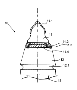
Fig. 1 shows a chisel (10) as a tool for fastening, for example by means of a
chisel holder, on a
machine used for road work and/or mining operations. As a functional unit for
striking against
the material to be worked, the chisel (10) features a chisel tip (11) on its
top end, essentially
consisting of a mechanically resistant material (e.g. with a modulus of
elasticity (E) between 550
and 720 GPa). In addition, the pointed end of the chisel tip (11) has a layer
of super-hard
cutting material (11.1) attached to it, which features an even greater
hardness than the chisel
tip (11) (e.g. with a modulus of elasticity between 720 and 1050 GPa). The
cutting material
(11.1) is made, for example, of polycrystalline diamond (PCD) and can be form-
locked and/or
integrally connected to the chisel tip (11). In this way, the wear resistance
of the chisel tip (11)
is further increased compared to a mechanically resistant material as the
contact area. A
shoulder (11.2) made of mechanically resistant material is molded in one piece
or form-locked
and/or integrally attached, e.g. soldered, to the bottom end of the chisel tip
(11), opposite the
top end. Underneath the shoulder (11.2), an oxidation protection layer (11.3)
can be provided
to protect the mechanically resistant material from corrosion. Underneath the
shoulder (11.2)
and/or the oxidation protection layer (11.3), a damping body (11.4) is
attached to the shoulder
(11.2) and/or the oxidation protection layer (11.3) as an intermediate
material of the chisel tip
(11) in a force-locked, form-locked, and/or integral manner. The damping body
(11.4) is
significantly more elastic than the rest of the chisel tip (11) (e.g. with a
modulus of elasticity
8
CA 03004502 2018-05-07
between 80 and 150 GPa), and can be made of copper, silver, nickel, or a
suitable alloy, for
example.
The chisel tip (11) with the shoulder (11.2) and the damping body (11.4) is
inserted into an
upwards-facing retainer provided for this purpose in the chisel body and
attached to the chisel
body (12) in a force-locked, form-locked, and/or integral manner; for example,
the shoulder
(11.2) can be soldered to the chisel body (12). The chisel body (12) is made
of steel and features
a circumferential nut (12.1) in its extension towards a downward-facing chisel
shaft (13). The
nut (12.1) serves as a tool retainer into which a dismantling tool can be
inserted. This
dismantling tool can be used to remove the chisel (10) from the chisel holder.
Other
embodiments of the chisel (10) are also conceivable.
The damping body (11.4) has the effect that when the chisel tip (11) strikes
the hard material to
be worked, the impact is absorbed due to the increased elasticity. This
results in a lower abrupt
impact stress of the chisel tip (11), as well as the chisel body (12) and the
machine. This can be
advantageous, particularly when PCD is used, since this material features a
lower impact
resistance than, for example, carbide metal. Overall, an increased stability
of the chisel (10) is
achieved.
As a further example of the tool proposed by the invention, Fig. 2 shows a
perspective top view
of a screening device (20). The screening device (20) can be used, for
example, in machines for
grading or pre-sorting loose material, such as rock and/or crushed materials,
but also in
agricultural applications. The screening device (20) features cross struts
(21) arranged
perpendicular to a direction of conveyance (F) of the loose material, as well
as longitudinal
struts (22) extending longitudinally to the direction of conveyance (F), with
rectangular screen
openings (23) being enclosed by the struts. Furthermore, the screening device
(20) features
side parts (24) on the side facing in the direction of the direction of
conveyance (F) and on the
opposite side, which contain apertures (60) for fastening the screening device
(20) to the
machine. The screen openings (23) in a first row (perpendicular to the
direction of conveyance
(F)) ¨ viewed from the direction of conveyance (F) ¨ are bordered by one of
the side parts (24)
on the side facing the direction of conveyance (F), and the screen openings
(23) in a final row
9
CA 03004502 2018-05-07
are bordered by the other side part (24) on the side facing away from the
direction of
conveyance (F).
As the tool body, the screening device (20) features a base unit (50) arranged
on its underside,
which is essentially made of a metal material, such as steel. As part of a
functional unit
intended as a wear protection element, a damping element (40), such as a
damping plate, is
form-locked and/or integrally attached to the base unit (50) as an
intermediate material. The
damping element (40) consists of a material featuring a higher elasticity than
the base unit (50).
In particular, it can be made of plastic and/or a composite material, and can
be attached to the
base unit (50), for example, by means of a casting process or other method. In
addition, an
oxidation protection layer (not shown here) could be provided between the base
unit (50) and
the damping element (40). On the top side of the screening device (20)
opposite the underside,
on which the loose material is conveyed, a wear protection layer (30) is
attached to the
damping element (40) as a further part of the functional unit. An oxidation
protection layer
could also be provided between the wear protection layer (30) and the damping
element (40).
Cross elements (31) of the wear protection layer (30) are arranged on the
cross struts (21), and
longitudinal elements (32) of the wear protection layer (30) are arranged on
the longitudinal
struts (22). The margin of the side part (24) forming the border of the screen
openings (23)
facing in the opposite direction of the direction of conveyance (F), i.e., in
the final row, is also
equipped with cross elements (31) (see Fig. 4). The margin of the side part
(24) forming the
border of the screen openings (23) facing in the direction of conveyance (F),
i.e., in the first row,
is equipped with longitudinal elements (32) even though the boundary is
transverse. The
reason for this is that the cross elements (31) are designed to encompass an
edge positioned
against the direction of conveyance (F) which is not present on this
transverse margin. The
cross and longitudinal elements (31, 32) are designed as wear-resistant by
ensuring they are
made of a mechanically resistant material. On those sections of the cross and
longitudinal struts
(21, 22) and also on segments of the border margins of the side parts (24)
which enclose one of
the screen openings (23), respectively, at least two cross or longitudinal
elements (31, 32) each
are arranged. These relatively short-segment design of the cross and
longitudinal elements (31,
32) advantageously reduces the probability of breakage of the cross and
longitudinal elements
(31, 32) when exposed to impact-type stress, thus increasing the resistance
capability of the
wear protection layer (30) and the wear protection element, respectively.
CA 03004502 2018-05-07
Fig. 3 illustrates a more detailed design of the base unit (50). On the
undersides of each of the
two side parts (24) of the screening device (20), the base unit (50) features
an angle element
(51). The supports (51.1) of the angle elements (51) are essentially
positioned parallel to the
top side of the screening device (20), as components of the side parts (24).
Perpendicular to
these and facing downward in a tipping direction (S) of the screened material,
guides (51.2) of
the angle elements (51) are attached, e.g. by welding, to the supports (51.1),
essentially
running along the bordering margins of the side parts (24). The angle elements
(51) are for the
precise fitting of the screening device (20) in the machine.
On the top side of the angle elements (51), a base plate (53) of the base unit
(50) is arranged
with side elements (51.1) as parts of the side parts (24). Furthermore, the
base plate (53)
features cross strut bodies (53.2) and longitudinal strut bodies (53.3) as
components of the
cross and longitudinal struts (21, 22). Underneath the longitudinal strut
bodies (53.3),
extending from the guide (51.2) on one side of the screening device (20) to
the guide (51.2) on
the opposite side, ligaments (52) are arranged which extend in the tipping
direction (S), roughly
equivalent to the dimension of the downward dimension of the guides (51.2).
The ligaments are
arranged underneath every second longitudinal strut (22), each starting on the
inside of the
outermost row of screen openings (23). The purpose of the ligaments is to
stabilize the base
unit (50) and/or the screening device (20).
Fig. 4 shows a top view of the screening device (20), providing a view of its
top side with the
wear protection layer (30). The quadrangular ¨ rectangular, in particular
¨screen openings (23),
each enclosed by sections of two longitudinal struts (22) and two cross struts
(21) and/or by
margins of the side parts (24), are visible. Their longitudinal direction is
aligned with the
direction of conveyance (F). Depending on the grading task, other shapes and
alignments of the
screen openings (23), such as square openings or rectangles with a
longitudinal direction
perpendicular to the direction of conveyance (F), are also conceivable.
Furthermore, Fig. 4
shows the wear protection layer (30) with the arrangement of the cross and
longitudinal
elements (31, 32). The longitudinal dimension of the elements (31, 32) is such
that per cross
and longitudinal strut (21, 22) section bordering a screen opening (23), at
least two elements
(31, 32) are arranged. This results in a segmentation of the wear protection
layer (30), which
minimizes the risk of breakage of the wear protection layer (30). The
segmentation could also
11
CA 03004502 2018-05-07
be achieved by means of larger and/or in particular also smaller elements (31,
32).
Furthermore, the illustration shows that the longitudinal elements (32) are
arranged in
immediate succession along the longitudinal struts (22), resulting in a
largely continuous
progression of the wear protection layer (30) formed by the longitudinal
elements (32) on the
longitudinal struts (22). In particular, the intersecting areas between the
cross and longitudinal
struts (21 and 22) are covered by longitudinal elements (32). In this way,
unwanted
irregularities and/or transition areas along the longitudinal struts (22) can
be advantageously
avoided, allowing the loose material largely moving in the direction of
conveyance (F) to flow
freely with fewer obstacles. Also, the longitudinal elements (32) are easier
to arrange in this
area since they feature no lateral legs, as Fig. 8 will illustrate later.
Fig. 5 shows a vertical section of the screening device (20) in the direction
of the tilting direction
(S), as identified in Fig. 4. The drawing clearly shows the layered structure
of the side parts (24),
with the supports (51.1) at the very bottom and the side elements (53.1) of
the base unit (50)
attached on top. Across the surfaces of the side elements (53.1), side element
covers (41) of the
damping element (40) are arranged, forming the top side of the side parts
(24). Furthermore, it
can be seen that the damping element (40) also covers the cross struts (21)
with a cross strut
layer (42) and the longitudinal struts (22) with a longitudinal strut layer
(43).
Fig. 6 shows an enlarged detail cross-section view of one of the cross-struts
(21) from Fig. 5,
showing their cross-section shape and structure in more detail. Lateral
surfaces (21.1) of the
cross strut (21) run between the top side (with the wear protection layer
(30)) and underside of
the cross strut (21), which are parallel to each other. The lateral surfaces
(21.1) are tilted in
relation to a median longitudinal plane (M) extending in the tipping direction
(S) and along the
cross strut (22) by an angle a (for example, a being between 2' and 15 , in
particular between
and 10 ) in such a way that the two lateral surfaces (21.1) converge in a
downwards
direction. Between the parallel top side and underside and the tilted lateral
surfaces (21.1), the
result is essentially a trapezoid cross-section of the cross strut (21). This
design of the cross
struts and also the longitudinal struts (see Fig. 8), as well as of the
bordering margins of the side
parts (24), results in a clear cross-section of the screen openings (23) that
grows larger in a
downwards direction (in the tipping direction (S)), which allows the screening
material to drop
through the screening device (20) more easily. The increasing clear cross-
section could also be
12
CA 03004502 2018-05-07
=
=
achieved with a different tilt of the lateral surfaces or a different
retreating design, such as an
arched or staggered design wherein some of the lateral surfaces could also
extend vertically
downwards.
The underside of the cross strut (21) is formed by the underside of the cross
strut body (53.2)
and a bottom end of the cross strut layer (42). The cross strut layer (42)
encompasses the cross
strut body (53.2) along its lateral surfaces and its top side. This reduces
the probability of direct
contact between the conveyed material and the cross strut body (53.2) and
ensures a good
damping effect. On top of the cross strut layer (42), the cross element (31)
is attached, with a
top-facing cross surface (31.1) as part of the wear protection layer (30). To
achieve a form-
locked and/or integral attachment to the cross strut layer (42), a connecting
part (31.2) is
molded into one piece with the cross element (31) on the underside of the
cross element (31)
opposite to the cross surface (31.1).
On the side facing against the direction of conveyance (F), a downward-facing
leg (31.3) is
molded to the cross element (31) to form a protective surface (31.4). The
protective surface
(31.4) forms part of the lateral surface (21.1) facing against the direction
of conveyance (F), and
it is tilted accordingly by the angle a. Thus, the angle between the cross
surface (31.1) and the
protective surface (31.4) is 900 - a. The protective surface (31.4) protects
the cross surface
facing against the direction of conveyance from the conveyed material, as the
direction of
conveyance causes the material to preferably impact on this side and/or edge
as well. To
ensure that there is enough room for sufficient damping material and a
sufficient damping
effect between the leg (31.3) and the cross strut body (53.2), the cross strut
body (53.2) is
shifted laterally in the cross strut (21) in relation to the median
longitudinal plane (M).
Fig. 7 shows a vertical section according to Fig. 4 along an area of one of
the cross struts (21)
through intersecting areas with two longitudinal struts (22). In the
intersecting areas, the wear
protection layer (30) is formed by longitudinal surfaces (32.1) of the
longitudinal elements (32).
Fig. 8 provides a more detailed view of a vertical section of a longitudinal
strut (22) shown in Fig
4, illustrating its structure and cross-section. Similarly to the cross struts
(21) (see Fig. 6), the
longitudinal strut (22) shown here also features an essentially trapezoid
cross-section with
tilted lateral surfaces (22.1) to form the expanding clear cross-section of
the screen openings
13
CA 03004502 2018-05-07
(23). The underside is essentially formed by the longitudinal strut body
(53.3) and, in a small
part, by the longitudinal strut layer (43). The longitudinal strut layer (43)
encompasses the two
lateral surfaces and the top side of the longitudinal strut body (53.3), so
the latter is largely
surrounded by damping material. On top of the longitudinal strut layer (43),
the longitudinal
element (32) is connected to the longitudinal strut layer (43) in a form-
locked and/or integral
manner. With its longitudinal surface (32.1), which completely covers the
longitudinal strut
layer (43) on the top side, the longitudinal element (32) forms part of the
wear protection layer
(30). Apart from a rounded transition to the lateral surfaces (32.3), the
remaining surfaces of
the longitudinal element (32) are embedded in the longitudinal strut layer
(43) in order to
achieve a defined surface formation of the wear protection layer (30) on the
longitudinal struts
(22), essentially on their top side. As a connecting element, a connecting
part (32.2) is molded
to the underside of the longitudinal element (32) in one piece. The structure
of the longitudinal
strut (22), unlike that of the cross strut (21), is symmetrical to its median
longitudinal plane (M).
Fig. 9 shows one of the apertures (60) identified in Fig. 4 as a vertical
section. The aperture (60)
features a recess (61) extending through the side element cover (41) and the
side element
(53.1). In particular, the purpose of the recess (61) is to receive the head
of a fastener, such as a
screw, to fasten the screening device (20) (not shown here). The recess (61)
ends in a duct (62)
extending downwards through the support (51.1) of the angle element (51). The
fastening
section of a fastener, such as a thread section (not shown here) can be guided
through the duct
(62).
To protect the head of the fastener and to form an essentially closed surface
of the side parts
(24), the apertures (60) are provided with a cover (63), which is shown in
Fig. 10a and 10b. The
cover (63) consists of the same material as the damping element (40), but
could also be made
of a different material. A cavity (63.2) in the cover (63) for encompassing
the head of a fastener
when fully assembled can be seen in the perspective view (Fig. 10a), as well
as in the vertical
section (Fig. 10b). Furthermore, the cover (63) features fin-shaped elements
(63.1) on its
outside circumference. The fin elements (63.1) are capable of yielding when
the cover (63) is
pressed up into the recess (61) and jamming the cover (63) in the recess (61).
14
CA 03004502 2018-05-07
Figures 11a and 11b show a perspective view from below and a top view of the
cross element
(31). It can be seen in Fig. 11a that its cross-section shape and the front
view, respectively,
continue across the longitudinal area of the cross element (31). Also visible
are the rounded
transitions of the individual surfaces on the underside, which is in contact
with the cross strut
layer (42). Specifically, this is the transition between a rear side of the
leg (31.3) and an
underside opposite to the cross surface (31.1), as well as its marginal
surfaces and the
transitions to the connecting part (31.2). The rounded transitions ensure that
the damping
material of the cross strut layer (42) lies evenly against the cross element
(31).
Figures 12a and 12b show a top and a front view of the longitudinal element
(32). Its cross-
section shape and front view also continue across the longitudinal area of the
longitudinal
element (32). In Fig. 12b, the essentially trapezoid cross-section of the
longitudinal element (32)
is visible. The longitudinal surface (32.1) and an opposite underside face
each other and are
parallel to each other. The top side and the underside are connected by
lateral surfaces (32.3)
tilt inwards towards the underside. The tilt is more pronounced than that of
the lateral surfaces
(22.1), so all sides of the longitudinal element (32), except for the
longitudinal surface (32.1)
and a rounded transition to the lateral surfaces (32.1) lie within the
longitudinal strut layer (43)
when assembled. The transitions between the surfaces are rounded, as are the
transitions to
the connecting part (32.2) molded in one piece to the underside.
The structure described results in a screening device (20) that is resistant
to wear and/or
impact or similar stress, due to the wear protection layer (30) made of
mechanically resistant
material, on the one hand. At the same time, the damping element designed as a
damping
plate partly absorbs the impact energy when materials such as rock-type
materials collide with
the mechanically resistant material. In this way, a longer service life of the
wear protection
layer (30) and a reduction of impact noise can be achieved in an advantageous
manner.
In another example not shown here, a ploughshare with its surface aligned in
the feed direction
could also be equipped with the functional unit proposed by the invention.