Note: Descriptions are shown in the official language in which they were submitted.
CA 03004666 2018-05-08
PCT/EP2017/059908 - 1 -
2015P16225W0
Description
Method for producing liquid pig iron
FIELD OF THE INVENTION
The invention relates to a method for producing liquid pig
iron, the method comprising
- reducing iron-oxide-containing feed materials to form a
partially reduced first iron product in a first reduction
system by means of a reducing gas and drawing off the reducing
gas consumed in the reduction as top gas or offgas,
- introducing the partially reduced first iron product, a first
oxygen-containing gas and a first carbon carrier into a melter
gasifier,
- gasifying the carbon carriers with the oxygen-containing gas
and melting the partially reduced first iron product to form
the liquid pig iron while producing the reducing gas in the
melter gasifier,
- introducing at least a partial amount of the reducing gas
into the first reduction system by means of a reducing gas
line.
In the case of such a smelting reduction process, gas cleaning
systems (on the one hand for the top gas or offgas from the
reduction system, on the other hand for the reducing gas from
the melter gasifier) are also generally provided, and,
depending on the system configuration, a device for removing
CO2 from the top gas or offgas, according to the prior art
usually by means of pressure swing adsorption, if this gas is
to be fed to a second reduction system or is to be used within
the smelting reduction process.
Known smelting reduction processes are the Corex process and
the Finex0 process. The Carex@ process is a two-stage smelting
reduction process. The smelting reduction combines the process
CA 03004666 2018-05-08
PCT/EP2017/059908 - 2 -
2015P16225W0
of indirect reduction (pre-reduction of iron oxide to form iron
sponge, often also referred to as direct reduction) with a
smelting process (including residual reduction) in the so-
called melter gasifier. The likewise known Finex process
differs from the Carex process by the direct use of iron ore
as fine ore, which is pre-reduced in a number of fluidized bed
reactors arranged one behind the other.
PRIOR ART
For the production of liquid pig iron, which is also intended
to include the production of products similar to pig iron,
there are essentially two known commonly used methods: the
blast furnace method and smelting reduction, the latter for
example as the Corex process or Finex process. The present
invention relates to smelting reduction.
Smelting reduction uses a melter gasifier, in which hot liquid
metal, preferably pig iron, is produced, and also at least one
reduction system, for instance at least one reduction reactor,
in which the carrier of the iron ore (lump ore, fine ore,
pellets, sinter) is at least partially reduced with reducing
gas, the reducing gas being produced in the melter gasifier by
gasifying mainly coal and coke with oxygen of technical purity
(oxygen content of 90% or more). During this gasification, the
required process heat is generated, and the reducing gas that
is required for the upstream stages of the process, such as
preheating, drying, iron reduction, calcination, etc.
Partially reduced means that the reduction degree of the iron
carrier material is increased in the reduction reactor, but the
reduction degree remains below 100%. The typical reduction
degree after the reduction system is between 50% and 90%. The
reduction degree RD is a measure of the depletion of the oxygen
from the oxide of the iron carrier material and is described by
the following formula
CA 03004666 2018-05-08
PCT/EP2017/059908 - 3 -
2015P16225W0
RD= (1- (0/ (1. 5*Fei-ot) ) ) *10 0
where 0 denotes the amount-of-substance fraction of the iron
carrier material accounted for by oxygen and Fetot denotes the
amount-of-substance fraction of the iron carrier material
accounted for by iron (in each case in mol%).
In the case of the smelting reduction process, either so much
solid carbon carrier is added that the amount of reducing gas
produced is sufficient to achieve the desired partial reduction
during the pre-reduction, with the disadvantage that the amount
of carbon carriers consumed is uneconomically high, or less
solid carbon carrier is added and the required amount of
reducing gas is made available by returning and treating
unconsumed process gas. This latter variant however
additionally requires at least one compressor and a CO2 removal
system, which causes increased investment costs and increased
energy consumption during operation.
SUMMARY OF THE INVENTION
An object of the invention is therefore to provide a method for
producing liquid pig iron with which the consumption of solid
carbon carriers in the melter gasifier can be reduced with
lowest possible expenditure on additional equipment or capital
expenditure.
The object is achieved by a method as claimed in claim 1, in
that the following further steps are carried out in the case of
a method described at the beginning:
- introducing a second gaseous and/or liquid carbon carrier and
also a second oxygen-containing gas into a mixing region within
the melter gasifier above the fixed bed (char bed) thereof,
- mixing the second gaseous and/or liquid carbon carrier with
the second oxygen-containing gas in the mixing region, the
CA 03004666 2018-05-08
PCT/EP2017/059908 - 4 -
2015P16225W0
combustion air ratio being set in the range of 0.2 to 0.45,
preferably between 0.3 and 0.35, to achieve partial oxidation
of the second gaseous or liquid carbon carrier within the
mixing region, and
- mixing the gas resulting from the partial oxidation from the
mixing region with the gas in the remaining volume within the
melter gasifier.
According to the invention, therefore, significant amounts of
only liquid, only gaseous or liquid and gaseous carbon carriers
are used to produce reducing gas from them in the form of H2
and CO, which reducing gas forms a significant part of the
overall reducing gas produced in the melter gasifier. The term
"second carbon carrier" means that it is different from the
first carbon carrier. The second carbon carrier may, however,
itself again comprise various substances and also be introduced
at a number of points of the melter gasifier, to which extent
it may of course also comprise third, fourth, etc. liquid
and/or solid carbon carriers. The second gaseous or liquid
carbon carrier may in particular contain natural gas, coke oven
gas, alkanes and aromatics (for example coke tar).
The second oxygen-containing gas is preferably oxygen of
technical purity with an 02 content of at least 90%. This
allows the nitrogen input into the melter gasifier to be kept
low. It also applies here that the "second oxygen-containing
gas" may contain gas from a number of sources and be introduced
into the corresponding mixing region or mixing regions of the
melter gasifier at a number of points, all of these gases being
referred to as "second oxygen-containing gas".
Therefore, according to the invention, a second gaseous or
liquid carbon carrier, spatially independent of the first
carbon carrier, and a second oxygen-containing gas, likewise
spatially independent of the first oxygen-containing gas, are
introduced into a mixing region (or a number of mixing regions)
CA 03004666 2018-05-08
PCT/EP2017/059908 - 5 -
2015P16225W0
within the melter gasifier. As far as possible, this mixing
region is not influenced by the remaining volume within the
melter gasifier with regard to gas flows, reactions and
temperature, in order that it is ensured that the second carbon
carrier and the second oxygen-containing gas are mixed with one
another without significant parts of the reducing gas that is
within the melter gasifier already adding to this mixture
before the second carbon carrier and the second oxygen-
containing gas have reacted with one another.
The mixing of the second carbon carrier and the second oxygen-
containing gas with the combustion air ratio according to the
invention causes a partial oxidation, that is to say that the
hydrocarbons of the second carbon carrier are predominantly
converted into carbon monoxide CO and hydrogen H2, and are
consequently available as reducing constituents of the reducing
gas.
In a small part (less than 25%), the oxygen of the oxygen-
containing gas and the hydrocarbons are completely oxidized in
the mixing region to form carbon dioxide CO2 and water H20. It
is consequently ensured that the temperatures in the mixing
region are sufficiently high (above 1000 C) to achieve a high
rate of conversion into reducing gas.
Likewise in a small part (less than 10%), the hydrocarbons of
the second carbon carrier are not broken down, or only into
smaller hydrocarbons. These hydrocarbons that are not broken
down, or only partially, can then be broken down further in the
remaining volume within the melter gasifier by dust particles
that are present in any case and act as a catalyst, also
containing inter alia metallic iron, without it being necessary
for catalysts to be added. For this reason, the resulting gas
from the mixing region is also fed to the remaining volume
within the melter gasifier.
CA 03004666 2018-05-08
PCT/EP2017/059908 - 6 -
2015P16225W0
Movable devices do not necessarily have to be provided for the
mixing in the mixing region; sufficient mixing is usually
achieved just by appropriate pressure and/or appropriate
directions when the second carbon carrier and the second
oxygen-containing gas are introduced. That is to say that the
direction of the second carbon carrier when it is introduced
into the mixing region may be different from the direction of
the second oxygen-containing gas when it is introduced into the
mixing region.
It is similarly probably unnecessary for a movable device to be
provided specifically for mixing the resulting gas from the
mixing region with the gas in the remaining volume of the
melter gasifier, this instead similarly being brought about
just by the pressure and direction when the second carbon
carrier and the second oxygen-containing gas are introduced,
because after all there is in any case a spatial connection
between the mixing region and the remaining volume of the
melter gasifier. The resulting gas from the mixing region mixes
with the gas in the remaining melter gasifier due to the heat
produced as a result of the partial oxidation and due to the
swirling of the second carbon carrier with the second oxygen-
containing gas.
The combustion air ratio is usually denoted by lambda and is
also known as the air ratio or air number. It is a
dimensionless quantity from combustion theory that indicates
the stoichiometric ratio of air, here the second oxygen-
containing gas, and fuel, here the second carbon carrier, in a
combustion process. With the combustion air ratio according to
the invention, a degree of oxidation of less than 25%, in
particular less than 15%, can be achieved in the partial
oxidation and an average temperature of 1150-1500 C can be
achieved in the mixing region of the second oxygen-containing
gas and the second carbon carrier.
CA 03004666 2018-05-08
PCT/EP2017/059908 - 7 -
2015P16225W0
It is admittedly known in principle also to introduce into a
melter gasifier gaseous carbon carriers in addition to the
first carbon carriers in lump form, see in this respect for
instance WO 2015/000604 Al, where in one design variant sulfur-
containing gas is introduced together with an oxygen-containing
gas into the melter gasifier. However, the introduction takes
place by means of a conventional oxygen burner which is not in
fact designed to operate in such a way as to maximize the yield
of reducing gas (H2 and CO), while at the same time minimizing
the formation of CO2, H20 and C, by setting a predefined mixing
ratio. Moreover, the conventional oxygen burner according to WO
2015/000604 Al lacks a defined spatial mixing region within the
melter gasifier for mixing gas and oxygen. At least, partial
oxidation under controlled conditions in the oxygen burner is
not disclosed in WO 2015/000604 Al. Use of greater amounts of
gaseous carbon carriers, as is possible in the case of the
method according to the invention as a result of the mixing
region, cannot be achieved by conventional oxygen burners
without specific control of the oxygen-containing gas in
relation to the gaseous carbon carriers, because without
control the degree of oxidation of the reducing gas formed
would be too high for the pre-reduction of the iron carriers in
the first reduction system.
In order to ensure a sufficiently high temperature for the
partial oxidation with at the same time a high yield of the
reducing gas components CO and H2 in the mixing region without
further devices, in a design variant it is provided that the
mixing region is surrounded by the reducing gas that is in the
melter gasifier. As a result, the heat losses of the mixing
region are minimized. The gas surrounding the mixing region
within the melter gasifier is typically at a temperature of
1050 C; the reaction zone in the mixing region is at a
temperature of 1150-1500 C, so that the reaction region of the
mixing region is in any case not significantly cooled down by
the surrounding gas. The dust in the gas within the melter
CA 03004666 2018-05-08
PCT/EP2017/059908 - 8 -
2015P16225W0
gasifier that surrounds the mixing region additionally reduces
the heat loss due to radiation of the mixing region to the
surrounding reducing gas.
In order to achieve mixing of the second carbon carrier and the
second oxygen-containing gas that is as undisturbed as
possible, it may be provided that the mixing region is at least
partially spatially separate from the remaining volume within
the melter gasifier.
For this purpose, it may be provided that the mixing region is
at least partially formed by an outwardly directed protrusion
of the inner wall of the melter gasifier. The inner wall of the
melter gasifier is therefore outwardly curved in a limited
region, in relation to the surrounding region. The protrusion
may for instance have approximately the form of a cylinder or
the form of a spherical cap, in particular a hemisphere. In
particular, the protrusion may be formed as a tube.
Where the protrusion adjoins the surrounding region of the
inner wall of the melter gasifier (that is to say at the
imaginary continuation of the inner wall of the melter gasifier
if no protrusion were present), the cross-sectional area of the
protrusion (always seen parallel to the surface area of the
inner wall without a protrusion) is at its greatest, as would
be the case with a protrusion in the form of a spherical cap.
It may however also be the case that the protrusion has a
greater cross-sectional area further outward, that is to say
that the protrusion has a constriction where it adjoins the
surrounding region of the inner wall. This constriction serves
the purpose of delimiting the mixing region better from the
remaining volume of the melter gasifier. In any case, the
mixing region formed by a protrusion may be additionally
increased in size by separating walls that protrude into the
interior of the melter gasifier.
CA 03004666 2018-05-08
PCT/EP2017/059908 - 9 -
2015P16225W0
In order to achieve good conditions for a catalytic reaction of
hydrocarbons that have not broken down when they leave the
mixing region, it may be provided that the mixing region is
above the fixed bed of the melter gasifier in a temperature
range of 1000-1100 C, in particular around 1050 C. This will
generally be the case if the mixing region is 1-2 m above the
fixed bed of the melter gasifier, for example at the same
height at which the dust burners are also arranged. This
additionally ensures a sufficient dwell time after the mixing
of the gas from the mixing region with the remaining reducing
gas that does not originate from the mixing region.
In order to achieve the highest possible yield of reducing gas
with the lowest possible input of solid carbon carriers, it may
be provided that, in the case of a gaseous second carbon
carrier, for example in the form of natural gas, more than
100 m3 of the second carbon carrier are fed to the melter
gasifier per tonne of pig iron, in particular more than 140 m3
per tonne of pig iron.
The partial oxidation according to the invention of liquid or
gaseous carbon carriers with oxygen of technical purity in the
melter gasifier for the first reduction system allows a
particularly low-nitrogen reducing gas to be produced, since it
is possible to dispense with the gas recycling of top gas or
offgas to the reducing gas and also the introduction of
pulverized coal, which usually takes place by means of nitrogen
as the means of delivery. For this reason, the reducing gas
produced according to the invention is also well suited for use
in a downstream direct reduction system. In this case it is
possible for instance to dispense with a reformer for producing
the reducing gas for the direct reduction system, since the
reducing gas is produced in the melter gasifier by the method
according to the invention. Correspondingly, it may therefore
be provided that the top gas or offgas is at least partially
introduced into a second reduction system, which is formed as a
CA 03004666 2018-05-08
PCT/EP2017/059908 - 10 -
2015P16225W0
direct reduction shaft or as a fluidized bed and in which
further iron-oxide-containing feed materials are reduced to
form a partially reduced second iron product, in particular to
produce iron sponge.
In a direct reduction system, lumpy iron ore carriers (lumpy
ore or pellets) or fine ore in a solid state is/are reduced at
750-1000 C by reducing gas. This produces direct reduced iron
(DRI for short), which is also referred to as iron sponge. The
direct reduction system contains as a key component a reduction
reactor, which is formed either as a reduction shaft in the
sense of a fixed bed reactor or in the form of fluidized bed
reactors, into which the lumpy iron ore or fine ore and the
reducing gas are introduced.
A direct reduction system may however also produce iron
briquettes, the hot reduced oxide materials being agglomerated
into larger units by means of hot briquetting (hot briquetted
iron, FBI for short, or hot compacted iron, HCI for short). So-
called low reduced iron (LRI for short) may also be drawn from
the reduction shaft or fluidized bed reactor of a direct
reduction system if the process is conducted appropriately.
A possible melter gasifier for carrying out the method
according to the invention comprises at least
- one iron product feed line for introducing the partially
reduced first iron product,
- one media feed line for introducing a first oxygen-containing
gas and
- one feed line for introducing a first carbon carrier into the
melter gasifier.
The melter gasifier is characterized in that at least one
carbon carrier line for introducing a second gaseous and/or
liquid carbon carrier and also at least one media feed line for
introducing a second oxygen-containing gas into a mixing region
CA 03004666 2018-05-08
PCT/EP2017/059908 - 11 -
2015P16225W0
within the melter gasifier above the fixed bed thereof are
provided, the mixing region being at least partially formed by
an outwardly directed protrusion of the inner wall of the
melter gasifier.
For example, it may be provided that the melter gasifier has a
dome and a conical region adjoining thereto, and the protrusion
is within 50-100%, in particular within 50-75%, of the height
of the conical region. Or it may be provided that the melter
gasifier has a dome and a conical region adjoining thereto, the
lower part of the dome being formed as a cylindrical region,
and the protrusion being within the cylindrical region.
The method according to the invention is distinguished by the
fact that liquid or gaseous hydrocarbons can be used to a
greater extent for producing liquid primary steel products, and
less solid carbon carriers have to be used. The latter are not
as readily available in some regions as liquid or gaseous
hydrocarbons. Since liquid or gaseous hydrocarbons have a
higher proportion of hydrogen than solid carbon carriers, this
hydrogen can easily be used for the reduction. Compressors and
CO2 removal systems and the associated energy costs can be
saved by the method according to the invention.
BRIEF DESCRIPTION OF THE FIGURES
The invention is explained in more detail below on the basis of
the figures, which are schematic and given by way of example.
Figure 1 shows an integrated plant according to the invention
comprising a melter gasifier and first and second reduction
systems,
Figure 2 shows the melter gasifier from Figure 1, with a first
embodiment of the mixing region,
CA 03004666 2018-05-08
PCT/EP2017/059908 - 12 -
2015P16225W0
Figure 3 shows the melter gasifier from Figure 1, with a second
embodiment of the mixing region provided by a protrusion in the
form of a tube.
WAYS FOR CARRYING OUT THE INVENTION
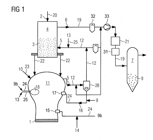
Figure 1 shows a system for carrying out the method according
to the invention for producing liquid pig iron 1 designed as a
Carex integrated direct reduction system. The iron-oxide-
containing feed materials 2 are fed to a first reduction system
4, a Carex@ reduction shaft with a fixed bed, by way of a feed
line 20 for supplying iron-oxide-containing feed materials 2.
The iron-oxide-containing feed materials 2 are reduced by means
of a reducing gas 5 to form a partially reduced first iron
product 3, which is subsequently introduced by way of one or
more iron product feed lines 22 opening out into a melter
gasifier 11 into the melter gasifier 11. Within the context of
the present text, the iron product 3 comprises iron both in an
oxidized, for example oxidic, form and in a reduced, that is to
say metallic, form. In the iron product 3, the iron may take
both forms; this is then referred to for example as pre-reduced
iron carrier material, which though not yet finally reduced
completely in comparison with a metallic form, is however
already reduced more in comparison with a previous state. It
may also take only one of the two forms. In the case of Corex0,
the iron product 3 is for example hot, so-called direct reduced
iron (DRI) or corresponding iron carrier material with a
metalization, which means it is not yet considered to be DRI.
In the case of the Corex process, the iron product 3 is
discharged from the reduction shaft of the first reduction
system 4 charged with hot reducing gas 5 and is transported by
means of gravitational force into the melter gasifier 11 by way
of one or more chutes, and if appropriate distributor flaps.
For example, a number of chutes may be provided, distributed
over the circumference of the dome of the melter gasifier 11.
CA 03004666 2018-05-08
PCT/EP2017/059908 - 13 -
2015P16225W0
In addition, solid carbon carriers as the first carbon carrier
10, in the form of lump coal and/or agglomerated fine coal
and/or coal-containing briquettes, are introduced into the
melter gasifier 11 by way of a feed line 23, and first oxygen-
containing gas 9, 9a is introduced by way of media feed lines
24. The charging of the first carbon carrier 10 and partially
reduced iron product 3 into the melter gasifier 11 generally
takes place separately from one another. The first carbon
carrier 10 is for example supplied from a storage container for
carbon-containing material by way of screw conveyors to a
distributing device, which is mounted centrally in the dome of
the melter gasifier 11 and by which the first carbon carrier 10
is distributed over the cross section of the melter gasifier 11
during the input into the melter gasifier 11, see in this
respect Figures 2 and 3.
The carbon carriers 10, and if appropriate the fine coal 14,
introduced into the melter gasifier 11 are gasified by means of
the oxygen-containing gas 9a producing the reducing gas 5. This
produces a gas mixture, which consists mainly of CO and H2.
The reducing gas 5 is introduced into the first reduction
system 4 by way of the reducing gas line 12, preceded by
dedusting in a dedusting device 26. The separated dust is
returned to the melter gasifier 11, to be specific by means of
one or more dust burners 17.
The first iron product 3 introduced into the melter gasifier 11
is melted by the heat produced during the gasification of the
carbon carriers 10 to form the liquid pig iron 1. The hot metal
smelted in the melter gasifier 11 and the slag are drawn off.
The reducing gas consumed during the reduction of the iron-
oxide-containing feed materials 2 is referred to as top gas 6
and is drawn off as export gas from the first reduction system
CA 03004666 2018-05-08
PCT/EP2017/059908 - 14 -
2015P16225W0
4 by way of an export gas line 19 and cleaned there by means of
wet scrubbers 32. The export gas may be compressed in a
compressor 33, subsequently subjected to CO2 removal 21 and
heating 31 and be introduced into a second reduction system 7
for producing a partially reduced second iron product 8, in
particular direct reduced iron (DRI) in the form of iron
sponge. For this second reduction system 7 there is
consequently no need for a system specifically for producing
reducing gas, for example a reformer, since this process takes
place in the melter gasifier 11.
After leaving the melter gasifier 11, part of the reducing gas
may be further cleaned in a wet scrubber 27, cooled and mixed
in with the export gas 6.
The melter gasifier 11 has introduction elements of three types
opening out into the melter gasifier 11, which are formed as an
oxygen nozzle 15, as a dust burner 17 and as a mixing region
18, which however may in each case also be multiply present. On
the outside, with respect to the melter gasifier 11, the
introduction elements are connected to the media feed lines 24
for the second oxygen-containing gas 9b. There is at least one
carbon carrier line 25, by means of which the second carbon
carrier 13, which may be liquid and/or gaseous, is introduced
into the melter gasifier 11. If the second carbon carrier is
gaseous, there may additionally also be in each case a carbon
carrier line 25 opening out into the reducing gas line 12.
A second carbon carrier 13 in liquid and/or in gas form, for
example coke oven gas or natural gas, is fed to the melter
gasifier 11 by way of the carbon carrier line 25, which opens
out into the mixing region 18.
Coke oven gas has a typical composition of
65 percent by volume hydrogen (H2),
2.5 percent by volume nitrogen (N2),
CA 03004666 2018-05-08
PCT/EP2017/059908 - 15 -
2015P16225W0
6 percent by volume carbon monoxide (CO),
22 percent by volume methane (CH4),
3 percent by volume other hydrocarbons (CnHm),
1.5 percent by volume carbon dioxide (CO2).
The carbon carrier line 25 may in this case be connected to a
coking plant.
Natural gas has a typical composition of
75-99 percent by volume methane,
1-15 percent by volume ethane,
1-10 percent by volume propane.
In addition, hydrogen sulfide, nitrogen and carbon dioxide may
be contained.
The second carbon carrier 13 and second oxygen-containing gas
9b in the form of oxygen of technical purity are introduced
into the mixing region 18, which is provided just above the
fixed bed of the melter gasifier 11 in the interior thereof,
here at the same height as the dust burner 17, under the dome.
The mixing region 18 is not separated here from the remaining
interior space of the melter gasifier 11 by internal
components, such as separating walls. During the operation of
the melter gasifier 11, the mixing region 18 is evident by the
reaction zone (flame), which is produced when there is complete
oxidation of a small part (less than 25%) of the second carbon
carrier 13 to form carbon dioxide CO2 and water H20. The media
feed line 24 for the second oxygen-containing gas 9b and the
carbon carrier line 25 open out into the mixing region 18. The
two lines may form an acute angle with one another, so that the
second oxygen-containing gas 9b and the second carbon carrier
13 move toward one another within the mixing region 18 and as a
result are mixed. There may also be a number of nozzles
provided for each of the two media 9b, 13, arranged such that
there is a swirling of the two media 9b, 13 when they enter the
mixing region 18 through the nozzles.
CA 03004666 2018-05-08
PCT/EP2017/059908 - 16 -
2015P16225W0
The mixing of the second carbon carrier 13 and the second
oxygen-containing gas 9b in the mixing region 18 causes a
partial oxidation, that is to say the hydrocarbons of the
second carbon carrier 13 are predominantly converted into
carbon monoxide CO and hydrogen H2. In a small part (less than
25%), the oxygen of the oxygen-containing gas 9b and the
hydrocarbons are completely oxidized in the mixing region 18 to
form carbon dioxide CO2 and water H20. This produces a flame
with a flame temperature of more than 1000 C, to be specific
approximately between 1150 and 1500 C, whereby there is a
sufficiently high temperature for the conversion into reducing
gas.
The small part (less than 10%) of hydrocarbons of the second
carbon carrier 13 that are not broken down, or only to smaller
hydrocarbons, in the mixing region 18 can then be broken down
further in the remaining volume within the melter gasifier 11
by dust particles that are present in any case and act as a
catalyst, also containing inter alia metallic iron.
A number of such mixing regions 18 may of course be provided,
for example a number of mixing regions 18 at the same height
and distributed over the circumference of the melter gasifier
11, a number of mixing regions 18 one above the other, or a
number of mixing regions one above the other and distributed
over the circumference.
In Figure 2, the melter gasifier 11 from Figure 1 is shown on
its own. A first carbon carrier 10 in the form of coal (solid
lines) is introduced into the melter gasifier 11 through the
middle outlet in the dome 30, into which the feed line 23 opens
out. The first carbon carrier 10 is in this case supplied by a
distributing device (not shown), which is mounted centrally in
the dome of the melter gasifier 11 and by which the first
CA 03004666 2018-05-08
PCT/EP2017/059908 - 17 -
2015P16225WO
carbon carrier 10 is distributed over the cross section of the
melter gasifier 11.
The iron product 3 from the reduction shaft of the first
reduction system 4, to be specific direct reduced iron DRI, is
transported by means of gravitational force into the melter
gasifier 11 by way of one or more iron product feed lines 22
formed as chutes. There are a number of such chutes distributed
over the circumference of the dome 30 of the melter gasifier
11.
Iron product 3 and carbon carriers 10 fall down through the
dome 30 into the conical region 29 of the melter gasifier 11
and form there the fixed bed 34, which here fills the conical
region 29 to approximately halfway. There is however also the
possibility of extending the lower part of the dome 30 in the
form of a cylinder and shortening the conical region 29. In
this case, the conical region 29 could even be completely
filled with the fixed bed 34. The passage of the carbon carrier
line 25 and the media feed line 24 or of the piece of line that
is shown, and consequently also the mixing region 18, would
then he arranged in the extended lower cylindrical region of
the dome 30. In the center of the fixed bed 34, below the
surface thereof, there is a reaction-free zone, which is
referred to as the dead man 35.
Both the second carbon carrier 13 and the second oxygen-
containing gas 9b are passed here through the wall of the
conical region 29 by means of a piece of line that represents a
continuation or unification of the carbon carrier line 25 and
the media feed line 24. The carbon carrier 13 and the second
oxygen-containing gas 9b may be mixed already in this piece of
line. They may however also be carried separately in this piece
of line (for instance in concentric pipes) and only mix in an
end region of the piece of line, which is formed for example as
a nozzle, or only after the end of the piece of line in the
CA 03004666 2018-05-08
PCT/EP2017/059908 - 18 -
2015P16225W0
interior of the melter gasifier 11. In any case, the (further)
mixing of the carbon carrier 13 and the second oxygen-
containing gas 9b and a partial oxidation take place in the
mixing region 18, which adjoins the piece of line shown.
The passage of the carbon carrier line 25 and the media feed
line 24 or the piece of line shown lies here approximately
between 50-75% of the height of the conical region 29 (measured
from the bottom) of the melter gasifier 11. Consequently, the
mixing region 18 is also at approximately between 50-75% of the
height of the conical region 29. Depending on the embodiment,
the arrangement may also lie above 75% of the conical region 29
or in the lower part of the dome 30, for instance if the lower
part of the dome 30 is formed as a cylindrical region.
Shown in Figure 3 is a variant of the design for the mixing
region 18 in the form of a protrusion, which is formed here by
a cylindrical tube 28. Otherwise, the construction of the
melter gasifier 11 and of the Corex0 plant are the same as
Figure 1 and Figure 2.
The cylindrical tube 28 has been inserted into a corresponding
opening in the melter gasifier 11 and finishes flush with the
inner wall of the melter gasifier 11, that is to say does not
protrude into the volume within the melter gasifier 11. The
media feed line 24 for the second oxygen-containing gas 9b and
the carbon carrier line 25 for the second carbon carrier 13
both open out into the mixing region 18, which on the one hand
is formed by the tube 28 itself, on the other hand also
protrudes into the remaining volume of the melter gasifier 11.
Undisturbed mixing of the second oxygen-containing gas 9b and
the second carbon carrier 13 can take place within the tube 28;
the energy for the partial oxidation within the tube 28 must in
this case likewise be provided by the partial oxidation of the
second carbon carrier 13, the losses being kept down by an
appropriate refractory lining of the tube 28.
CA 03004666 2018-05-08
PCT/EP2017/059908 - 19 -
2015P16225W0
In order to ensure that the mixing region 18 extends as far as
possible into the interior of the melter gasifier 11, and
consequently the heat losses in the mixing region 18 can be
kept down, the longitudinal axis of the tube 28 may be aligned
normal to the tangential plane of the inner wall of the melter
gasifier 11. In Figure 3, the tube 28 is aligned approximately
horizontally.
The diameter of the tube 28 is generally a multiple of the
diameter of a media feed line 24 or of a carbon carrier line 25
or of a dust burner 17 or of the outlet opening of an oxygen
nozzle 15.
In order to be able to convert more of the second carbon
carrier 13, a number of tubes 28 per melter gasifier 11 may be
provided. In this case, the tubes 28 and the associated mixing
regions 18 may be distributed over the circumference and/or the
height of the melter gasifier 11 - as explained in the case of
Figure 1.
The two lines 24, 25 may again form an acute angle with one
another, so that the second oxygen-carrying gas 9b and the
second carbon carrier 13 move toward one another within the
mixing region 18, in particular within the tube 28, and as a
result are mixed. There may also be a number of nozzles
provided for each of the two media 9b, 13, arranged such that
there is a swirling of the two media 9b, 13 when they enter the
mixing region 18, in particular the tube 28, through the
nozzles.
Both for mixing regions 18 without a protrusion and for mixing
regions 18 with a protrusion, it applies that they are
preferably arranged 1-2 m above the fixed bed 34. As shown in
Figures 2 and 3, the mixing region or regions 18 may for
example be under the dome 30 of the melter gasifier 11 in the
CA 03004666 2018-05-08
PCT/EP2017/059908 - 20 -
2015P16225WO
conical region 29 of the melter gasifier 11 or in the lower
part of the cylindrically extended dome 30. The conical region
29 is the frustoconically upwardly widening part of the melter
gasifier 11, to which the approximately hemispherical dome 30
adjoins.
If instead of the Carex plant a Finex0 plant is used, after
the last of the three to four fluidized bed reactors, in which
the pre-reduction of the fine ore takes place, a partial stream
of the offgas is removed as export gas, and otherwise used as
in Figure 1. As in the case of the Corex plant, part of the
surplus gas from the melter gasifier 11 may also be added to
the export gas.
CA 03004666 2018-05-08
PCT/EP2017/059908 - 21 -
2015P16225W0
List of designations:
1 liquid pig iron
2 iron-oxide-containing feed materials
3 partially reduced first iron product
4 first reduction system
reducing gas
6 top gas
7 second reduction system
8 partially reduced second iron product
9 oxygen-containing gas
9a first oxygen-containing gas
9b second oxygen-containing gas
first carbon carrier
11 melter gasifier
12 reducing gas line
13 second carbon carrier
14 fine coal
oxygen nozzle
16 dust
17 dust burner
18 mixing region
19 export gas line
feed line for supplying iron-oxide-containing feed
materials
21 CO2 removal
22 iron product feed line
23 feed line for the first carbon carrier 10
24 media feed line
carbon carrier line
26 dedusting device
27 wet scrubber
28 protrusion (tube)
29 conical region of the melter gasifier 11
dome of the melter gasifier 11
31 heating
CA 03004666 2018-05-08
PCT/EP2017/059908 - 22 -
2015P16225W0
32 wet scrubber for top gas
33 compressor
34 fixed bed
35 dead man