Note: Descriptions are shown in the official language in which they were submitted.
CA 03004709 2018-05-08
WO 2017/146715 PCT/US2016/019689
SEMI- RIGID BULK MATERIAL STORAGE CONTAINER
TECHNICAL FIELD
The present disclosure relates generally to the handling of dry bulk
materials, and
more particularly, to a semi-rigid bulk material storage container for use in
the storage,
transportation and dispensation of such dry bulk materials.
BACKGROUND
During the drilling and completion of oil and gas wells, various wellbore
treating
fluids are used for a number of purposes. For example, high viscosity gels are
used to create
fractures in oil and gas bearing formations to increase production. High
viscosity and high
density gels are also used to maintain positive hydrostatic pressure in the
well while limiting
flow of well fluids into earth formations during installation of completion
equipment. High
viscosity fluids are used to flow sand into wells during gravel packing
operations. The high
viscosity fluids are normally produced by mixing dry powder and/or granular
materials and
agents with water at the well site as they are needed for the particular
treatment. Systems for
metering and mixing the various materials are normally portable, e.g., skid-
or truck-
mounted, since they are needed for only short periods of time at a well site.
The powder or granular treating material is normally transported to a well
site in a
commercial or common carrier tank truck. Once the tank truck and mixing system
are at the
well site, the dry powder material (bulk material) must be transferred or
conveyed from the
tank truck into a supply tank for metering into a blender as needed. The bulk
material is
usually transferred from the tank truck pneumatically. More specifically, the
bulk material is
blown pneumatically from the tank truck into an on-location storage/delivery
system (e.g.,
silo). The storage/delivery system may then deliver the bulk material onto a
conveyor or into
a hopper, which meters the bulk material through a chute into a blender tub.
Recent developments in bulk material handling operations involve the use of
portable
containers for transporting dry material about a well location. The containers
can be brought
in on trucks, unloaded, stored on location, and manipulated about the well
site when the
material is needed. The containers are generally easier to manipulate on
location than a large
supply tank trailer. The containers are eventually emptied by dumping the
contents thereof
onto a mechanical conveying system (e.g., conveyor belt, auger, bucket lift,
etc.). The
conveying system then moves the bulk material in a metered fashion to a
desired destination
1
CA 03004709 2018-05-08
WO 2017/146715 PCT/US2016/019689
at the well site.
Currently, most containers that are used for proppant handling with respect to
hydraulic fracturing operations are steel. Steel is readily available and very
familiar for many
supply chain operators and has great characteristics with respect to strength
and durability.
However, steel is a very dense material and many of the operations or
procedures used when
handling the material can be very expensive. This includes the equipment used
for
manufacturing processes (brake, saw, welding machines, etc.) as well as the
manual labor
needed to complete the manufacturing processes. Many of these issues have been
addressed
with the design of a soft-sided container, which is the subject of a separate
application filed
by the assignee of the present application hereof That application was filed
on December 3,
2015 and has been assigned Serial No. PCT/US2015/063773.
The present disclosure presents another approach at addressing many of these
same
issues by employing a semi-rigid container the details of which are discussed
in further detail
herein.
2
CA 03004709 2018-05-08
WO 2017/146715 PCT/US2016/019689
BRIEF DESCRIPTION OF THE DRAWINGS
For a more complete understanding of the present disclosure and its features
and
advantages, reference is now made to the following description, taken in
conjunction with the
accompanying drawings, in which:
FIG. 1 is an isometric view of a semi-rigid panel-type bulk material storage
container,
in accordance with an embodiment of the present disclosure;
FIG. 2 is a cutaway perspective view of an alternate embodiment of the semi-
rigid
panel-type bulk material storage container shown in FIG. 1 revealing the
inside of a
containment structure of the bulk material storage container;
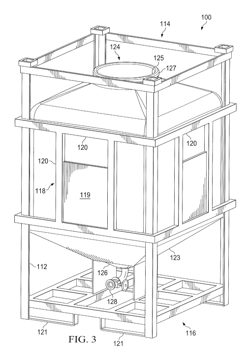
FIG. 3 is an isometric view of a semi-rigid roto-molded type bulk material
storage
container, in accordance with another embodiment of the present disclosure;
and
FIG. 4 is a side view of the semi-rigid roto-molded type bulk material storage
container shown in FIG. 3 equipped with alternative outlet discharge valve.
3
CA 03004709 2018-05-08
WO 2017/146715 PCT/US2016/019689
DETAILED DESCRIPTION
Illustrative embodiments of the present disclosure are described in detail
herein. In
the interest of clarity, not all features of an actual implementation are
described in this
specification. It will of course be appreciated that in the development of any
such actual
embodiment, numerous implementation specific decisions must be made to achieve
developers' specific goals, such as compliance with system related and
business related
constraints, which will vary from one implementation to another. Moreover, it
will be
appreciated that such a development effort might be complex and time
consuming, but would
nevertheless be a routine undertaking for those of ordinary skill in the art
having the benefit
of the present disclosure. Furthermore, in no way should the following
examples be read to
limit, or define, the scope of the disclosure.
Certain embodiments according to the present disclosure may be directed to
systems
and methods for efficiently managing bulk material (e.g., bulk solid or liquid
material). Bulk
material handling systems are used in a wide variety of contexts including,
but not limited to,
drilling and completion of oil and gas wells, concrete mixing applications,
agriculture, and
others. The disclosed embodiments are directed to systems for efficiently
moving bulk
material into a blender inlet of a blender unit at a job site. The systems may
include a
portable support structure used to receive one or more portable containers of
bulk material
and output bulk material from the containers directly into the blender inlet.
The disclosed
techniques may be used to efficiently handle any desirable bulk material
having a solid or
liquid constituency including, but not limited to, sand, proppant, gel
particulate, diverting
agent, dry-gel particulate, liquid additives and others.
In currently existing on-site bulk material handling applications, dry
material (e.g.,
sand, proppant, gel particulate, or dry-gel particulate) may be used during
the formation of
treatment fluids. In such applications, the bulk material is often transferred
between
transportation units, storage tanks, blenders, and other on-site components
via pneumatic
transfer, sand screws, chutes, conveyor belts, and other components. Recently,
a new method
for transferring bulk material to a hydraulic fracturing site involves using
portable containers
to transport the bulk material. The containers can be brought in on trucks,
unloaded, stored
on location, and manipulated about the site when the material is needed. These
containers
generally include a discharge gate at the bottom that can be actuated to empty
the material
contents of the container at a desired time.
The present disclosure is directed to the use of a semi rigid material for the
4
CA 03004709 2018-05-08
WO 2017/146715 PCT/US2016/019689
containment structure. The semi-rigid material may comprise a thin sheet of
steel, a roto-
molded polyethylene (polypropylene, polycarbonate, polyvinyl chloride,
combinations
thereof or similar thermoplastic material), fiber reinforced plastic, carbon
graphite panels, or
other light, semi-rigid yet strong material. The roto-molded material/process
approach can
have use in other container applications. It is also a cost effective solution
because the
containers can be manufactured in high quantities for low cost. There is no
welding required
with these approaches, which significantly reduces the manufacturing time and
thus
associated cost of manufacture. Also, the roto-molded polyethylene approach is
also a very
light yet strong material. A roto-molded container could be used in bulk
storage as set forth
herein.
Furthermore, the containers in accordance with the present disclosure are
intended to
be stackable, when being transported or stored and also when being placed on a
frame above
a blender or mixer for dispensing. To facilitate their stacking, each
container frame must be
robust enough to carry the weight of its stack. Furthermore, each frame is
equipped with
alignment pins to facilitate the stacking of the containers.
Turning now to the drawings, FIG. 1 illustrates a schematic diagram of a semi-
rigid
bulk material storage container 10 in accordance with the present disclosure.
The container
10 includes a frame 12, which includes a top 14, a bottom 16 and a plurality
of sides 18. The
frame is formed of a plurality of interconnected rigid bars 20, which in one
exemplary
embodiment may be formed of steel. As those of ordinary skill in the art will
appreciate,
however, alternative rigid materials may be used in the construction of the
frame 12. The
grade/weight of steel or other rigid material utilized should be able to carry
the weight of
multiple containers such as when the containers are stacked. A pair of
parallel channels 21 is
attached to the bottom 16 of the frame 12 at generally opposite sides, as
shown in FIG. 2.
The channels 21 have a general rectangular cross-section and are designed to
accommodate
the forks of a forklift. This enables the containers 10 to be easily hoisted
onto and off
transportation units (not shown) and also moved around a well site.
One of the features of the frame 12 is that the rigid bars 20 are formed at
least on the
sides into a cross-bar configuration. These cross-bars reinforce the frame 12.
Unlike prior
art bulk material storage containers, whose frames are made up of solid
panels, frame 12
simply relies on the cross-bars to give it form and strength. This
configuration results in a
lighter-weight container 10 which has a greater capacity for storage of bulk
material. Indeed,
the reduction in material making up the frame 12 together with the use of
light weight semi-
5
CA 03004709 2018-05-08
WO 2017/146715 PCT/US2016/019689
rigid material used to form the storage containment structure 22 reduces the
overall weight of
the container by approximately 31% or more over prior art containers. This
weight savings
will allow an approximate additional 2,000 lbs. of dry bulk material to be
transported in each
container, which results in an approximate 5% increase over current capacity
of existing
conventional bulk material storage containers. Furthermore, the fabrication
expenses
associated with the design of the present bulk material storage container 10
will also result in
a significant reduction in the fabrication cost for the containers. It is
estimated that by
eliminating the conventional side panels and associated welding of same, that
a reduction of
approximately 100 hours of fabrication time will result in connection with the
manufacture of
the bulk storage material containers 10, in accordance with the present
disclosure.
An inlet 24 is located in the top 14 of the frame 12. The inlet 24 is formed
by two
orthogonal pairs of parallel cross bars. One or more hatches 26 may be mounted
to the inlet
24 by a pair of hinges 28 and 30. The pair of hinges 28 and 30 enables the
hatch to swing
between an open position and a closed position. In the open position, dry bulk
material can
be disposed into the container 10 through the opening 24. In the closed
position, the dry bulk
material is contained within the container 10 thereby preventing it from being
lost to the
environment or exposed to undesired moisture. Bulk material loss can be an
issue during
transport and in windy environments. Thus, the hatch 26 assists in the
containment of the
bulk material storage. The container 10 is also formed with a plurality of
alignment pins 25
disposed on the top 14 of the frame 12 and an associated plurality of
alignment recesses 27
disposed on the bottom of the frame 12. The associated alignment recesses 27
are designed
to receive the alignment pins 25 from another container 10 to thereby enable
stacking of the
containers 10.
The storage containment structure 22 is formed of an upper portion 40 and a
lower
portion 42, which are best seen in FIG. 2. The upper portion 40 is formed of a
semi-rigid
material, such as, e.g., thin sheets of steel, carbon graphite panels, or
fiber reinforced plastic
panels. The bottom portion 42 is formed of the same semi-rigid material, which
is used to
form the upper portion 40. The panels can be formed together using structural
adhesives,
rivets, threaded fasteners, welding (steel or thermoplastic) or a combination
of any of these
techniques. As those of ordinary skill in the art will appreciate, other
suitable materials and
attachment techniques may be used.
The upper portion 40 of the storage containment structure 22 has a top section
44, a
mid-section 46 and bottom section 48. The mid-section 46 is formed of a
plurality of side
6
CA 03004709 2018-05-08
WO 2017/146715 PCT/US2016/019689
panels, which are attached to each other at adjacent corners. The side panels
are attached at
right angles to each other (i.e., 900 angles). The top section 44 is formed of
a plurality of
upwardly tapered panels, which are attached on their sides to each other at
adjacent corners.
The upwardly tapered panels are also attached to the side panels of the mid-
section along a
bottom perimeter and to a rim 50, which forms part of the inlet 24 and hatch
26 along a top
perimeter. The bottom section 48 is similar in shape to the top portion 44. It
is formed of a
plurality of downwardly tapered panels which are attached to each other at
adjacent corners.
The downwardly tapered panels are also attached to the side panels of the mid-
section along a
top perimeter and to the lower portion 42 of the storage containment structure
22 along a
bottom perimeter. The bottom section 48 is funnel-shaped and acts to direct
the bulk material
downwardly towards the bottom of the container 10 and ultimately out of the
container upon
dispensing.
In the embodiment where the upper portion 40 and lower portion 42 are formed
of
fiber reinforced panels, carbon graphite panels or thin sheet steel, the upper
portion 40 and
lower portion 42 are attached to the top 14 and bottom 16 of the frame 12
using rivets,
threaded fasteners, welding (steel or thermoplastic) or a combination of such
attachment
techniques. Those of ordinary skill in the art will be aware of other suitable
attachment
techniques, which may alternatively be used.
The container 10 is formed with a discharge opening 60, which is best shown in
FIG.
2. The discharge opening 60 may be equipped with a gate valve or other similar
device for
controlling the flow of the bulk material out of the containment structure 22.
It may also
optionally be configured to allow for choke-feeding of the bulk material out
of the container
10.
Furthermore, the top 14 of frame 12 may be completely open as shown in FIG. 2
and
not formed with a hatch 26 or other permanent cover. Rather, the storage
containment
structure 22 may be formed with an opening 27, which may be formed with a lip
29. The lip
29 is useful in removably securing a lid (not shown) to the containment
structure 22, e.g., via
snap-fit connection or by other means. The benefit of this design is that if
the storage
containment structure 22 becomes damaged or otherwise becomes in need of
replacement,
the entire container 10 does not have to be repaired or discarded. Rather, a
replacement
containment structure 22 can easily be installed into the frame 12. In one
exemplary
embodiment, the storage containment structure 22 is simply supported within
the frame 12 by
support bars 52, as best illustrated in FIG. 2. The storage containment
structure 22 may
7
CA 03004709 2018-05-08
WO 2017/146715 PCT/US2016/019689
optionally fastened to the support bars 52, or just simply sit on said bars
under its own
weight. The former configuration allows for quick removal of the storage
containment
structure. This design is also employed in the alternate embodiments described
below with
reference to FIGs. 3 and 4. In yet another alternative design, the tapered
bottom section 48 is
formed of a plurality of tapered interconnected panels, which are integrally
formed with the
frame 12. This embodiment is shown in FIG. 1.
FIGs. 3 and 4 show alternative embodiments of the semi-rigid bulk storage
container
in accordance with the present disclosure. The container in these embodiments
is referred to
generally by reference numeral 100. The container 100 includes a frame 112,
which includes
a top 114, a bottom 116 and a plurality of sides 118. The frame is formed of a
plurality of
rigid bars 120, which in one exemplary embodiment may be formed of steel. The
frame may
optionally have one or more plates 119, formed between and supported by the
rigid bars 120.
The frame 112 also comprises a plurality of tapered panels or plates 123 in
the bottom
portion, which used to support the weight of the containment structure 122 and
its contents.
As those of ordinary skill in the art will appreciate, however, alternative
rigid materials may
be used in the construction of the frame 112. The grade/weight of steel or
other rigid material
utilized should be able to carry the weight of multiple containers such as
when the containers
are stacked. A pair of parallel channels 121 is attached to the bottom 116 of
the frame 112 at
generally opposite sides. The channels 121 have a general rectangular cross-
section and are
designed to accommodate the forks of a forklift. This enables the containers
to be easily
hoisted onto and off transportation units (not shown) and also moved around a
well site.
Furthermore, in one exemplary embodiment, the frame 112 is open at the top to
enable easy
removal and replacement of the storage containment structure 122 in the event
of damage or
destruction.
The container 100 includes storage containment structure 122, which in this
embodiment is formed of a roto-molded plastic material. The benefit of this
design is that the
storage containment structure 122 can be formed in a single step by machine
and at high
volume, thus reducing the manufacturing cost of this significant component of
the container
100. The roto-molding process also has the benefit of producing a containment
structure
which has a uniform thickness with a high degree of accuracy. This enables the
dimensions
to be tightly controlled, and thus enables the containment structures to be
manufactured only
to a necessary thickness and weight.
The containment structure 122 is an integrally formed structure and is
generally
8
CA 03004709 2018-05-08
WO 2017/146715 PCT/US2016/019689
cylindrical in its mid-section and may be generally tapered or flat at its top
and bottom
sections. The containment structure 122 is formed with an inlet 124 at its top
and an outlet
126 at its bottom. The inlet 124 comprises an aperture 125 which is designed
to allow bulk
material to be dispensed easily into the containment structure 122 with
minimal to no
spillage. A lid (not shown) may be secured to the top of the containment
structure 122 over
the aperture 125. The lid may be secured to the containment structure 122,
e.g., by one or
more hinges or may be removable, e.g., through a snap fit seal or via a
threaded connection.
In the embodiment shown in FIGs. 3-4, the aperture 125 is formed with a lip
127 at the top of
the taper. The lip 127 is useful in securing the lid to the containment
structure 122, e.g., via
snap-fit connection.
The outlet 126 is equipped with a gate valve 128, which may be one of many
different
designs. Exemplary gate valves include a sliding gate, roller gate, clamshell
gate, metering
gate or similar device. The gate valve 128 is used to regulate flow of the
bulk material out of
the containment structure 122. As those of ordinary skill in the art will
appreciate, other
types of flow control mechanisms can be used to control the flow of bulk
material out of the
containment structure 122. Also, as those of ordinary skill in the art will
also appreciate,
electronically controlled gate valves may be used. Such gate valves would be
particularly
useful in connection with an integrated computerized control system.
It should be noted that the disclosed container 10 may be utilized to provide
bulk
material for use in a variety of treating processes. For example, the
disclosed systems and
methods may be utilized to provide proppant materials into fracture treatments
performed on
a hydrocarbon recovery well. In other embodiments, the disclosed techniques
may be used to
provide other materials (e.g., non-proppant) for diversions, conductor-frac
applications,
cement mixing, drilling mud mixing, and other fluid mixing applications.
Although the present disclosure and its advantages have been described in
detail, it
should be understood that various changes, substitutions and alterations can
be made herein
without departing from the spirit and scope of the disclosure as defined by
the following
claims.
9