Note: Descriptions are shown in the official language in which they were submitted.
1
"WASTE BIN-CARRYING FRAMEWORK AND DRAWER, IN PARTICULAR FOR
THE WASTE SEPARATE COLLECTION-
PRIORITY CLAIM
This application claims priority from Italian Patent
Application No. 102017000052303 filed on May 15, 2017, the
disclosure of which is incorporated by reference.
This patent application relates to a waste bin-
carrying framework and to a drawer, in particular for the
waste separate collection.
Normally, a drawer for the waste separate collection
consists of a bracket installed inside the compartment of
a cabinet where the drawer operates, a framework sliding
along the bracket and configured to support one or more
waste bins, a front door fixed to the framework.
The cabinet and the door are usually built by the
furniture maker and the bracket generally is supplied by
the furniture maker to be installed inside the cabinet.
On the other hand, the waste bin-carrying framework is
built by a supplier of the furniture maker. Therefore, the
supplier manufacturing the frameworks is forced to find
technical solutions that can adjust to the different
CA 3004861 2018-05-14
2
cabinet and bracket formats offered by furniture makers.
The main problems currently arising lie in the fact
that, given the same width of the compartment where the
drawer needs to operate, each furniture maker installs its
own bracket with shapes and sizes that are different from
those installed by other furniture makers.
Known waste bin-carrying frameworks are made of sheet
metal and are manufactured as one single piece. As a
consequence, framework manufacturers must produce a series
of models thereof, each configured for the type of bracket
used by the furniture maker. Furthermore, the bracket with
the frameworks currently available in the market remains
visible and, therefore, not only is it unsightly, but it
also collects dust and possible waste parts (we remember
the type of use of the drawer).
In addition, the brackets currently available in the
market can be mounted so as to horizontally project inside
the compartment, these guides are not very good to look at
and substantially forbid the application of known
frameworks and the usual installation of waste bins.
Finally, in current frameworks it is hard to adjust the
width thereof so as to obtain a precise and effective
support for the waste bins.
An object of the invention is to provide a waste bin-
carrying frameworks that are pleasant to look at and
CA 3004861 2018-05-14
3
linear, waste bin adjust to different furniture formats
and, at the same time, permit the application of economies
of scale.
A further object of the invention is to provide a
waste bin-carrying framework that can easily adjust to
commonly used cabinets, is easy and cheap to be
manufactured and can easily be installed.
A further object of the invention is to provide a
waste bin-carrying framework that permits economies of
scale and can be easily changed so as to be adjusted to
different cabinets.
According to the invention, there is provided a waste
bin-carrying framework according to the appended claims.
According to the invention, there is further provided
a drawer according to the appended claims.
The invention will now be described with reference to
the accompanying drawings, which show non-limiting
embodiments thereof, wherein:
- figure 1 is a perspective view of a drawer according
to the invention;
- figure 2 is a perspective view of a waste bin-
carrying framework according to the invention during the
use and with some components removed for greater clarity;
- figure 3 is an exploded view of the detail of figure
2;
CA 3004861 2018-05-14
4
- figure 4 is similar to figure 2 and is a perspective
view of a different version of a waste bin-carrying
framework according to the inventions;
- figure 5 shows a particular of figure 3;
- figure 6 shows a further particular of figure 3;
- figures 7 and 8 shows two respective different
versions of a particular of figure 3.
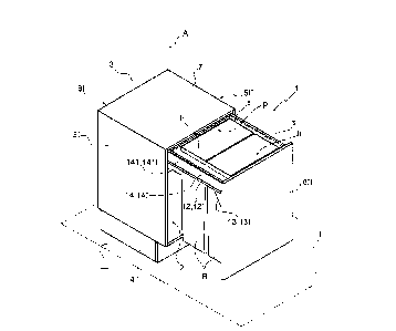
In figure 1, number 1 indicates, as a whole, a drawer
1, in particular for the waste separate collection, which
is installed inside a compartment 2 obtained in a cabinet
3. In particular, the cabinet 3 substantially has the shape
of a parallelepiped with a longitudinal axis A and
comprises:
- a base 4 configured to be arranged on a supporting
surface n and a shelf 7, which are parallel to and opposite
one another;
- a right side wall 51 and a left side wall 511, which
are parallel to and opposite one another;
- a rear back 61 and a front door 611, which are
parallel to and opposite one another.
The door 611 is selectively movable from a closing
position to an opening position, and vice versa.
Hereinafter, the terms right/left and front/rear are used
with reference to the arrangement shown in figure 1 and in
order to indicate elements that tare parallel to one
CA 3004861 2018-05-14
5
another and substantially perpendicular to the supporting
surface n. The term horizontal means substantially parallel
to the supporting surface n and the term vertical means
substantially perpendicular to the supporting surface n.
Furthermore, in the description below:
- height means the extension along the longitudinal
axis A;
- width means the distance between the right side wall
51 and the left side wall 511 and an extension parallel
thereto;
- depth means the distance between the back 61 and the
door 611, when the door 611 is closed and an extension
parallel thereto.
The drawer 1 is a sliding drawer and further comprises
a waste bin-carrying framework 8, which is mounted inside
the compartment 2 and connects the door 611 to the side
walls 51 and 511. Therefore, the door 611 translates in an
integral manner with the waste bin-carrying framework 8
from a closing position to an opening position, and vice
versa.
In particular, the drawer 1 has a height that is such
as to allow it to accommodate waste bins R.
The waste bin-carrying framework 8 is configured to
house waste bins R having a cup-shaped body with the shape
of a rectangular parallelepiped and an inner cavity h,
CA 3004861 2018-05-14
6
which can be accessed through a top opening p.
Preferably, the waste bins R have a top edge s, which
delimits the top opening p and is configured to allow the
trash waste bin R to be connected to the waste bin-carrying
framework 8 with a shape coupling or through interference.
The waste bin-carrying framework 8 supports the door
611. The waste bin-carrying framework 8 is movable, in
particular can slide, inside the compartment 2. The waste
bin-carrying framework 8 comprises a frame 9 and a
connection element 10, which connects the frame 9 to the
cabinet 3 and permits a relative movement, in particular
sliding, between the frame 9 and the cabinet 3.
According to the example shown in figures 2 and 3, the
connection element 10 is a bracket comprising:
- a guide 12, which is configured to be fixed in a
known manner to a respective side wall of the cabinet 3 and
comprises, in turn, in a known manner, a track 121 and a
slide 122, which is mounted so as to slide along said
track; and
- a case 11, which is mounted on the slide 122 of the
guide 12, so as to slide along the respective track 121;
the case 11 connects the guide 12 to the frame 9.
Advantageously, the connection element 10 comprises,
furthermore, an angle 13, which connects the door 611 to
the guide 12. According to figures 2 and 3, the angle 13 is
CA 3004861 2018-05-14
7
known. The angle 13 is connected to the case 11.
Advantageously the case 11 is U shaped and is made by
a folded metal sheet. The case 11 is fitted around the
respective guide 12 and has a horizontal flat surface 111.
Advantageously, the bracket 10 is made of a metal
material.
According to the example shown in figures 2 and 3, the
waste bin-carrying frame 8 comprises a right bracket 101
and a left bracket 1011, which connect the frame 9 to the
right side wall 51 and to the left side wall 511,
respectively. Furthermore, the waste bin-carrying framework
8 comprises a right case 111 and a left case 1111, which
are coupled, in a known and sliding manner, to the right
guide 121 and to the left guide 1211, respectively.
The frame 9 of the framework 8 comprises:
- two side boards, hereinafter referred to as right
side board 141 and left side board 1411; and
- two cross bars, hereinafter referred to as front
cross bar 151 and rear cross bar 1511, respectively.
Preferably, the cross bars 151 and 1511 are
perpendicular to the side boards 141 and 1411.
The cross bars 151 and 1511 have the same width. The
cross bars 151 and 1511 are chosen within a group of cross
bars 151 and 1511 having different widths. In other words,
the width of the bars 151 and 1511 is variable depending on
CA 3004861 2018-05-14
8
the width of the compartment 2. The cross bars 151 and 1511
can be made of a metal material, for example sheet metal.
The side boards 141 and 1411 are equal to mirror-like
relative to one another. The side boards 141 and 1411 are
made of a polymer material. The side boards 141 and 1411
are manufactured by means of polymer material processing
process. Advantageously, each side board 14 is manufactured
as one single piece. Advantageously each side board 14 has
an external surface 141 which is flat. Advantageously each
side board 14 is placed on the respective horizontal flat
surface 111 of the case 11. Each side board 14 is connected
to the respective flat surface 111 of the case 11.
Each external surface 141 is visible when the door 611
is in the opening position (as shown in figure 2). Each
external surface 141 is parallel to and overlooks the
respective side wall 5. A flat/plain external surface 141
prevent from collecting dust and possible waste parts
between the waste bin-carrying frame 8 and the cabinet 3.
The right side board 141 is fixed to the right
carriage 121. The left side board 1411 is fixed to the left
carriage 1211. The side boards 121 and 1211 are
substantially parallel to one another and are configured so
as to slide along the side walls 51 and 511, respectively.
Each side board 141 or 1411 is arranged on the respective
carriage 121 or 1211, namely it rests on the respective
CA 3004861 2018-05-14
9
carriage 121 or 1211 and does not laterally projects from
the latter.
By so doing, the space taken up by the connection
element 10 inside the compartment 2 is minimized, thus
maximizing the use of the available space. Furthermore,
each side board 141 or 1411 hides the respective carriage
121 or 1211.
The frame 9 further comprises a supporting wall 18,
which is connected crosswise to a respective side board 14
and projects inside the waste bin-carrying framework 8. The
supporting wall 18 has a width that is such as to ensure
the housing and the bearing of a waste bin R.
Advantageously, the supporting wall 18 is made of a
polymer material. The supporting wall 18 is manufactured
by means of polymer material processing process.
The supporting wall 18 is chosen within a group of
supporting walls 18 having different sizes, in particular
having different widths. The supporting wall 18 is chosen
depending on the sizes of the waste bin R to be supported
and on the width of the compartment 2.
Advantageously, the supporting wall 18 is made so as
to cover possible releasable connection elements, for
example screws, connecting the respective abutment wall 14
to the carriage 12 of the bracket 10. By so doing it is
possible to obtain a continuous and uniform surface,
CA 3004861 2018-05-14
10
avoiding the presence of edges or corners where possible
dirt can accumulate.
Advantageously, the supporting wall 18 is connected to
the respective side boards 14 with releasable means, for
example screws. In this way, the supporting surface 18 can
be replaced with another one having different sizes, in
case there is a change in the sizes, in particular in the
width, of the waste bin R to be supported or of the
compartment 2 in which it is inserted.
According to the example shown in figures 2 and 3, the
waste bin-carrying framework 8 comprises a right supporting
wall 181 and a left supporting wall 1811. The right
supporting wall 181 is substantially parallel to the
supporting surface n, namely perpendicular to the
respective right side board 141. Similarly, the left
supporting wall 181 is substantially parallel to the
supporting surface n, namely perpendicular to the
respective left side board 1411.
Advantageously, each side board 14 has projecting
elements 142 which project, in use, toward the respective
supporting wall 18. Each supporting wall 18 has a housing
181 which is configured to be coupled with the projecting
elements 142 of the respective side board 14 so as to form,
in use, a shape connection. According to the example shown
in the figures, each supporting wall 18 has a housing 181
CA 3004861 2018-05-14
11
which faces, in use, the respective side board 14. Each
side board 14 has a C shaped projecting elements 142, which
are housed, in use, inside the respective housing 181. By
so doing, it is guarantee a high mechanical strength of
each supporting wall 18 and of the waste bin-carrying
framework 8.
In figures 4 and 5, number 108 indicates a different
version of the waste bin-carrying framework shown in
figures 2 and 3. Figures 4 and 5 show an assembly
consisting of waste bins R' and a waste bin-carrying
framework 108 having a different format from the one shown
in figures 2 and 3. In particular, the waste bin-carrying
framework 108 is configured to suit to a compartment (not
shown) having a smaller width than the compartment 2.
The components shown in figures 4 and 5 are
substantially the same as the ones shown in figures 2 and
3; therefore, the same components are considers as included
in the framework 108 without having to discuss them again
and they also keep the same numbers. On the other hand,
those components that are similar, but have different sizes
keep the same numbers, but in the order of hundreds.
In particular, figures 4 and 5 show that the waste
bin-carrying framework 108 has cross bars 1151, 11511 with
smaller sizes than the cross bars 151 and 1511 of the
framework 8. The supporting walls 1181 and 11811 have
CA 3004861 2018-05-14
12
smaller sizes than the walls 181 and 1811 of the framework
8, as well. On the other hand, the abutment walls 14 and
the brackets 10 are substantially equal.
Owing to the above, the waste bin-carrying framework
8, 108 can easily adjust to compartments 2 with different
widths or can accommodate waste bins R, R' with different
sizes by simply changing some components (in particular,
the cross bars 15 and/or the supporting walls 18).
Furthermore, in figures 7 and 8 with 218 and 318,
respectively, are indicated respective versions of the
supporting wall 18.
Owing to the above, the side boards 14 and the
brackets 10 can be used to build a wide range of waste bin-
carrying frameworks 8 and can be produced in large numbers,
thus permitting economies of scale in the production.
Furthermore, the fact that the side boards 14 and the
supporting walls 18, 118, 218, 318 are made of a polymer
material reduces manufacturing times and costs.
Furthermore, the fact that the side boards 14 and the
supporting walls 18, 118, 218, 318 are made of a polymer
material reduces transportation weights and costs.
The waste bin-carrying framework 8, 108 of the type
described above further allows users to maximize containing
spaces, as the space take up by the brackets 10, namely by
the cases 11 and the guides 12, is used to support the
CA 3004861 2018-05-14
13
respective side boards 14.
The waste bin-carrying framework 8, 108 of the type
described above further allows users to simply adjust the
sizes of the frame 9, 109, in particular the width, if
necessary even upon installation thereof.
CA 3004861 2018-05-14