Note: Descriptions are shown in the official language in which they were submitted.
CA 03004935 2018-05-10
WO 2017/080530 PCT/CN2016/105834
SELF-BALANCING BOARD WITH PRIMARY WHEEL AND
DISTAL AUXILIARY WHEEL
Cross-Reference To Related Applications
[0001] This application claims the benefit of PCT Patent Application No.
PCT/162015/058821, filed on November 15, 2015, the contents of which are
incorporated herein by reference in their entirety.
Field of the Invention
[0002] This invention relates to transportation vehicles for individuals,
particularly a self-balancing board such as a device known as a one-wheeled
skateboard which incorporates a motorized primary wheel.
Backoround of the Invention
[0003] Self-balancing vehicles for transportation of individuals are known
in the
art. As described in U56302230B1 and AT299826 (Kamen), such vehicles are
typically equipped with two coaxial, individually driven wheels, spaced apart
and
with a platform between, onto which a rider of the vehicle may stand facing in
an
intended forward direction of motion. Gyroscopic and accelerometer sensors
detect
changes in orientation of the platform and feed information to a motor control
system. The motor system is programmed to maintain platform orientation
horizontal within a certain range by rotating the wheels in any direction,
having the
effect of aligning the centers-of-gravity of the vehicle and the rider whilst
the vehicle
has a constant velocity. On some types, there is an upright handlebar
connected to
the platform, giving the rider ability to further control the vehicle by
leaning
sideways, whereby the wheels will rotate at different speeds and/or direction,
causing the vehicle to turn.
[0004] Another variant of the above-described self-balancing vehicle is
taught
by U58738278B2 (Chen) in which a vehicle has two spaced, individually powered
1
CA 03004935 2018-05-10
WO 2017/080530 PCT/CN2016/105834
wheels that are controlled by a motor control system, with a platform between
which is split laterally in two halves. Each half of the platform is
associated with one
wheel and its motor control system, and corresponds to the position of left
and right
feet of a rider of the vehicle. The two halves are pivotally coupled to one
another,
whereby the rider can control the relative speed and rotation direction of the
two
wheels independently using their feet to tilt the two platform sections. One
benefit of
this type of self-balancing vehicle is the lack of need for an upright
handlebar,
making the unit smaller and maneuverable without using the hands.
[0005] A third type of self-balancing vehicle disclosed by US2011220427A1
(Chen) a single large wheel and footrests on either side of the wheel.
Friction pads
extending upwards from each footrest are designed to give the rider more
stability
and comfort by providing support to the inside of the rider's calves.
[0006] A fourth type of self-balancing vehicle has a single wheel and a
platform
shaped like that of a skateboard. The rider places one foot on each side of a
centrally positioned single wheel, and the intended direction of travel is
sideways
relative to the orientation of the rider. US910817 Doerksen describes such a
vehicle. There are also developments described in the art towards the safety
aspects of this type of vehicle. Although the nature of an electric DC motor
is that it
can also be used in reverse as a brake, whereby the motor is used as a dynamo
and electric energy is generated, more braking power may be desired.
CN103191558A (Chu) describes a similar self-balancing board with a separate
brake mechanism acting on the single central wheel, thereby increasing the
braking
power. US7811217 (Odien) discloses a self-balancing board with dual centrally
positioned wheels, each having a brake associated with it. US7424927B2
(Hiramatsu) also describes a self-balancing board with a single central wheel,
having auxiliary wheels in front and back. The auxiliary wheels are used to
sense
board angle via contact with a surface, each auxiliary wheel having sensors to
determine the time the board has spent in a certain max tilt angle and feed
2
CA 03004935 2018-05-10
WO 2017/080530 PCT/CN2016/105834
information to the motor controller in order to initiate a controlled
deceleration of the
motor, and thus the central wheel.
Summary
[0007] According to an aspect, there is provided a self-balancing board,
including a primary wheel assembly that includes a primary wheel and a motor
driving the primary wheel. The board further includes a platform secured to
the
primary wheel assembly and having a foot deck, at least one sensor sensing the
orientation of the platform, a controller receiving data from the at least one
sensor
and controlling the motor in response to the received data, a first auxiliary
wheel
assembly coupled to the platform distal the primary wheel assembly, the first
auxiliary wheel assembly being elevated from contacting a flat surface upon
which
the primary wheel rests when the foot deck is parallel to the flat surface,
and a first
brake element that is manually movable relative to the first auxiliary wheel
assembly to engage the first auxiliary wheel assembly to provide resistance to
rotation of the first auxiliary wheel assembly.
[0008] The self-balancing board can further comprise a first brake pedal
being
biased to a disengaged position and being movable to an engaged position in
which the first brake element contacts the first auxiliary wheel assembly.
[0009] The first brake pedal can be coupled to the platform via a
mechanical
hinge.
[0010] The first brake pedal can be coupled to the platform via a living
hinge.
[0011] The first brake element can comprise a first brake pad, the first
brake
element being linearly biased away from the first auxiliary wheel assembly,
and
wherein the first brake element can be manually moved towards the first
auxiliary
wheel assembly to cause the first brake pad to come into contact with the
first
auxiliary wheel assembly.
[0012] The first auxiliary wheel assembly can be biased away from the
platform,
and wherein pressure applied to the platform proximal to the first auxiliary
wheel
3
CA 03004935 2018-05-10
WO 2017/080530 PCT/CN2016/105834
assembly when the first auxiliary wheel assembly urges the first auxiliary
wheel
assembly into contact with the first brake element.
[0013] The first auxiliary wheel assembly can comprise a first auxiliary
wheel,
and a first braking surface.
[0014] The first brake element can engage the first braking surface to
provide
resistance to rotation of the first auxiliary wheel assembly.
[0015] The self-balancing board can further include a second auxiliary
wheel
assembly coupled to the platform distal the primary wheel assembly, the second
auxiliary wheel assembly being elevated from contacting a flat surface upon
which
the primary wheel rests when the foot deck is parallel to the flat surface,
and a
second brake element that is manually movable relative to the second auxiliary
wheel assembly to engage the second auxiliary wheel assembly to provide
resistance to rotation of the second auxiliary wheel assembly.
[0016] The self-balancing board can further comprise a second brake pedal
being biased to a disengaged position and being movable to an engaged position
in
which the second brake element contacts the second auxiliary wheel assembly.
[0017] The second brake pedal can be coupled to the platform via a
mechanical
hinge.
[0018] The second brake pedal can be coupled to the platform via a living
hinge.
[0019] The second brake element can comprise a second brake pad, the
second brake element being linearly biased away from the second auxiliary
wheel
assembly, and wherein the second brake element can be manually urged towards
the second auxiliary wheel assembly to cause the second brake pad to come into
contact with the second auxiliary wheel assembly.
[0020] The second auxiliary wheel assembly can be biased away from the
platform, and wherein pressure applied to the platform proximal to the second
auxiliary wheel assembly when the second auxiliary wheel assembly urges the
second auxiliary wheel assembly into contact with the second brake element.
4
CA 03004935 2018-05-10
WO 2017/080530 PCT/CN2016/105834
[0021] The self-balancing board can further comprise a handle bar secured
to
the platform.
Brief Description of the Drawings
[0022] Embodiments will now be described, by way of example only, with
reference to the attached Figures, wherein:
[0023] Fig. 1 is a side perspective view of a self-balancing board in
accordance
with an embodiment;
[0024] Fig. 2 is a side perspective view with a rider positioned atop of
the self-
balancing board of Fig. 1;
[0025] Fig. 3a is a top view of the self-balancing board of Fig. 1;
[0026] Fig. 3b is a side view of the self-balancing board of Fig. 1;
[0027] Fig. 3c is a bottom view of the self-balancing board of Fig. 1;
[0028] Fig. 3d is a rear view of the self-balancing board of Fig. 1;
[0029] Fig. 4 is an exploded view of the self-balancing board of Fig. 1;
[0030] Fig. 5 is an exploded view of the wheel assembly of the self-
balancing
board of Fig. 1;
[0031] Fig. 6a is a side section view of the self-balancing board of Fig.
1 with
the brake disengaged ;
[0032] Fig. 6b is a side section view of the self-balancing board of Fig.
1 with the
brake engaged;
[0033] Fig. 7a is a side view of the self-balancing board of Fig. 1 in
normal
operation;
[0034] Fig. 7b is a side view of the self-balancing board of Fig. 1 in
anti-fall
mode ;
[0035] Fig. 70 is a side view of the self-balancing board of Fig. 1 in
brake mode;
[0036] Fig. 8 is a side perspective view of an alternative configuration
of the
self-balancing board of Fig. 1, wherein a handlebar replaces a brake pedal;
CA 03004935 2018-05-10
WO 2017/080530 PCT/CN2016/105834
[0037] Fig. 9 is a side sectional view of a self-balancing board in
accordance
with another embodiment having a linearly movable auxiliary wheel assembly;
[0038] Fig. 10 is a side view of a self-balancing board in accordance with
a
further embodiment having a pivotally movable auxiliary wheel assembly; and
[0039] Fig. 11 is a side sectional view of a self-balancing board in
accordance
with another embodiment having a linearly movable brake pad.
Detailed Description of the Embodiments
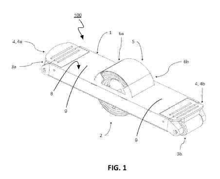
[0040] Figs. 1, 2, 3a, 3b, 3c, and 3d show a self-balancing board 100 in
accordance with an embodiment. Self-balancing board 100 has a platform 1 that
is
generally elongated and has a generally central opening in which a primary
wheel
assembly 2 is secured. Platform 1 has an upper surface 8 that includes two
foot
rests 9 on either side of primary wheel assembly 2 upon which a rider 7
stands. The
plane generally extending through foot rests 9 defines a foot deck that
happens to
be coplanar with upper surface 8 in this embodiment.
[0041] Primary wheel assembly 2 includes a primary wheel 2a that protrudes
out of the generally central opening both below and above platform 1.
Accidental
contact between the feet of rider 7 and primary wheel assembly 2 is generally
prevented by fenders 6a and 6b extending from upper surface 8 of platform 1
and a
wheel cover 5 spanning fenders 6a, 6b over primary wheel assembly 2. The axis
of
rotation of a wheel of primary wheel assembly 2 defines a z axis. An x axis is
orthogonal to the z axis and is parallel to a flat surface upon which the
wheel is
rested on. As will be appreciated, self-balancing board 100 is driven by
primary
wheel assembly 2 in either direction along the x axis.
[0042] A first auxiliary wheel assembly 3a is rotationally coupled to a
first end of
platform 1, and a first brake pedal 4a is connected via a mechanical hinge to
platform 1 to brake first auxiliary wheel assembly 3a. A second auxiliary
wheel
assembly 3b identical to first auxiliary wheel assembly 3a is rotationally
coupled to
6
CA 03004935 2018-05-10
WO 2017/080530 PCT/CN2016/105834
a second end of platform 1, and a second brake pedal 4b is connected via a
mechanical hinge to platform 1 to brake second auxiliary wheel assembly 3b.
[0043] As shown in Fig. 2, self-balancing board 100 enables a person to
stand
thereon straddling a centrally and symmetrically positioned wheel with his or
her
feet. Acceleration and deceleration of self-balancing board 100 can be
controlled by
placing more weight on one foot relative to the other, thus tilting self-
balancing
board 100. Sensors in self-balancing board 100 detect the orientation of the
platform 1 and control a motor driving the wheel to accelerate or decelerate
as
needed to maintain the platform 1 in a generally level orientation.
[0044] Fig. 4 illustrates various components of self-balancing board 100
in
greater detail. Wheel cover 5 is secured to an underside of platform 1 and
extends
upwards within opening 10, after which primary wheel assembly 2 is secured
within
opening 10 via wheel shaft brackets 22. Fenders 6a, 6b are separate elements
that
are fastened to platform 1.
[0045] A controller board 11 having a controller and orientation sensors
is
located under platform 1 in a location provided by a PCB tray 16. A battery
tray 17
provides location for a battery assembly that includes a lower battery cover
18, a
battery 19, a battery PCB 20, and an upper battery cover 21. Battery 19 can be
one
or more batteries coupled together to provide power to self-balancing board
100.
Battery PCB 20 controls the charging of and power flow provided by battery 19.
Lower and upper battery covers 18 and 21 protect and isolate battery 19 and
battery PCB 20 from physical damage and from electrical interference. Once PCB
tray 16, battery tray 17, and primary wheel assembly 2 are secured to platform
1, a
bottom cover 23 is secured to the bottom of platform 1.
[0046] Auxiliary wheel assemblies 3a and 3b are secured at ends of
platform 1.
Each of auxiliary wheel assembly 3a and auxiliary wheel assembly 3b includes
an
elongated auxiliary wheel 12, an auxiliary wheel bearing member 13, an
auxiliary
wheel shaft 14, and wheel nuts 15. Elongated auxiliary wheel 12 is preferably
made
of a resilient material such as rubber. Auxiliary wheel bearing member 13 may
be a
7
CA 03004935 2018-05-10
WO 2017/080530 PCT/CN2016/105834
bushing or a bearing. In embodiments wherein auxiliary wheel bearing member 13
is a bushing it is preferably made of a deformation-resistant material that is
suitable
as a bushing, such as certain selected types of plastic. Auxiliary wheel shaft
14 is
preferably constructed from a suitable metal. Auxiliary wheel shafts 14 of
auxiliary
wheel assemblies 3a and 3b are secured to platform 1 via wheel nuts 15 at both
ends. The profile of auxiliary wheels 12 is such that the auxiliary wheels 12
touch
the ground before the platform 1 touches the ground when the platform 1 is
tipped
forward or rearward.
[0047] Coupled in a pivoting relation to platform 1 and close to auxiliary
wheel
assemblies 3a and 3b are brake pedals 4a and 4b. Each brake pedal 4a, 4b is
mechanically hinged to platform 1 via hinge posts 31. Biasing members 32 (e.g.
torsion springs) are positioned on hinge posts 31 and between brake pedals 4a,
4b
and platform 1.
[0048] Fig. 5 illustrates various components of primary wheel assembly 2
in
greater detail. Primary wheel assembly 2 includes a tire 24 that is made of a
suitable rubber. A motor 25 is placed inside of tire 24 and is secured between
two
wheel hub sections 26, 27 that are dimensioned to fit tightly inside of tire
24 via
friction-fit or by any other suitable connection structure. Motor 25 has an
axel that is
secured at each end to wheel shaft bracket 22 via wheel shaft nuts 28. Primary
wheel assembly 2 is then secured to platform 1 via wheel shaft brackets 22.
Power
may be transmitted from the battery 19 to the motor 25 through a hollow shaft
supporting the wheel assembly 2 on the platform 1. The motor 25 may be a hub
motor that includes a central portion that is the stator and a radially outer
portion
that is a rotor and rotates about the stator.
[0049] Referring now to Figs. 4 and 5, the controller uses orientation
data
provided by the orientation sensors for the platform 1 and controls motor 24
based
on the orientation data. When the rider shifts their weight to one end of
platform 1,
thereby tilting platform 1 around the z axis, the controller controls motor 24
to
accelerate self-balancing board 100 in the direction to which weight was
shifted.
8
CA 03004935 2018-05-10
WO 2017/080530 PCT/CN2016/105834
[0050] Figure 6a shows brake pedal 4 at either end of platform 1 of self-
balancing board 100 in a disengaged position. Flanged portions 29 of brake
pedal 4
receive auxiliary wheel shaft 14 through a hole, enabling an end 30 of brake
pedal
4 to pivot therearound. Brake pedal 4 has a brake pad 31 on a surface of end
30
facing auxiliary wheel 12. When brake pedal 4 is not urged to pivot downwards
(i.e.,
in a disengaged position), springs 32 bias end 30 and brake pad 31 of brake
pedal
4 away from auxiliary wheel 12. When end 30 and brake pad 31 of brake pedal 4
are urged to pivot towards auxiliary wheel 12 by manual exertion of a force P
on an
opposite surface of end 30 into an engaged position, brake pad 31 engages
auxiliary wheel 12 and the friction force between brake pad 31 and auxiliary
wheel
12 works to brake auxiliary wheel 12, as shown in Fig. 6b. Upon termination of
the
force P, end 30 of brake pedal 4 is urged back into the position shown in Fig.
6a by
springs 32.
[0051] As shown in Fig. 7a, self-balancing board 100 has a freedom of
movement F of approximately plus or minus eight degrees around the z axis (of
the
primary wheel) before auxiliary wheel 12 at either end of platform 1 contacts
a flat
surface upon which self-balancing board 100 is resting. The angle is found to
be
suitable for an intuitive use of the board but can vary depending on other
factors
relating to board performance.
[0052] Assuming a single direction of travel T for illustration, three
main user
situations are possible. Self-balancing board 100 can be in balance, as shown
in
Fig. 7a, during which its velocity, either zero or non-zero, is constant. In
addition,
auxiliary wheel assembly 3a enables a smooth transition when traversing uneven
terrains, such as a speed bump 32.
[0053] As shown in Fig. 7b, weight can be shifted forward by the rider to
tilt the
leading end of platform 1 downwards up to eight degrees towards the surface
over
which self-balancing board 100 is traveling. When the controller receives
orientation
data from the orientation sensors on controller board 11 in this position, the
controller directs motor 25 to accelerate self-balancing board 100 at full
power in
9
CA 03004935 2018-05-10
WO 2017/080530 PCT/CN2016/105834
direction T and auxiliary wheel assembly 3a facilitates forward movement of
self-
balancing board 100. Brake pedal 4b and brake pad 31 are biased away from
auxiliary wheel 3b towards a disengaged position by springs 32.
[0054] Alternatively, as shown in Fig. 7c, weight can be shifted backward
by the
rider to tilt the trailing end of platform 1 downwards eight degrees towards
the
surface over which self-balancing board 100 is traveling. When the controller
receives orientation data from the orientation sensors on controller board 11
in this
position, the controller directs motor 25 to decelerate self-balancing board
100,
using the motor as a brake, at full power in the direction opposite of T,
causing self-
balancing board 100.
[0055] The rider can further increase deceleration of self-balancing board
100
by manually pressing down with their foot on brake pedal 4b to urge brake
pedal 4b
and brake pad 30 to an engaged position to engage auxiliary wheel assembly 3b.
The braking force between brake pad 30 and auxiliary wheel assembly 3b is
proportional to the manual force applied to brake pedal 4b, and self-balancing
board 100 can be brought to a more rapid stop than if only relying on the
motor
brake provided by motor 25.
[0056] As will be appreciated, motor 24 of self-balancing board 100 can
operate
both clockwise or counterclockwise, so that self-balancing board 100 can
travel in
the direction opposite of T. In this reverse direction, the same principles
are applied
by self-balancing board 100. Tilting of the leading end of platform 1 towards
the
surface being traveled over causes the controller to direct motor 24 to
accelerate in
that direction. Similarly, tilting of the trailing end of platform 1 towards
the surface
being traveled over causes the controller to direct motor to decelerate. The
rider 7
can further increase deceleration of self-balancing board 100 in the direction
opposite of T by manually urging brake pedal 4a and brake pad 30 connected
thereto to engage auxiliary wheel assembly 3a, thereby applying a mechanical
braking force to auxiliary wheel assembly 3a.
CA 03004935 2018-05-10
WO 2017/080530 PCT/CN2016/105834
[0057] Fig. 8 shows an alternative configuration for self-balancing board
100'.
Self-balancing board 100' is similar to self-balancing board 100, except that
brake
pedal 4a has been removed and replaced with a handlebar bracket 35 to which a
handlebar 34 is secured. Brake pedal 4b is left in place and can be operated
by the
rider to brake self-balancing board 100'. In this alternative configuration,
first
auxiliary wheel assembly 3a may also be removed.
[0058] While, in the above described embodiment, movable brake pedals that
are coupled to the platform via mechanical hinges are used to engage auxiliary
wheel assemblies to provide resistance to rotation of the auxiliary wheel
assemblies, other types of brake elements can be employed to engages the
auxiliary wheel assemblies. For example, a brake pedal can be provided via a
living
hinged portion of the platform, where the respective portion of the platform
is
suitably flexible to enable manual biasing of the brake pedal between a
disengaged
position and an engaged position.
[0059] In another alternative embodiment shown in Fig. 9, the brake
element is
a brake actuator 200 traveling generally linearly through a bore of a platform
204
and being secured to a brake pad 208. Brake actuator 200 is biased to a
disengaged position via a biasing mechanism such as spring 212 or the like in
which brake pad 208 is not in contact with an auxiliary wheel assembly 216.
Brake
actuator 200 may be manually biased through the bore to cause brake pad 208 to
engage auxiliary wheel assembly 216. Other types of brake elements that are
manually movable to engage the auxiliary wheel assemblies will occur to those
skilled in the art.
[0060] An auxiliary wheel assembly can be movable towards the platform to
which a brake pad may be fixed. For example, Fig. 10 shows a further
alternative
embodiment in which an auxiliary wheel assembly 300 is mounted on a cylinder
304 that slidably receives a post 308 secured to a platform 312. Cylinder 304
is
biased away from platform 312 via a spring 316 or the like. A brake pad 320 is
secured to platform 312. By manually shifting weight when auxiliary wheel
11
CA 03004935 2018-05-10
WO 2017/080530 PCT/CN2016/105834
assembly 300 is in contact with a surface, spring 316 can be compressed so
that
auxiliary wheel assembly 300 engages brake pad 320. Thus, in this case,
platform
312 adjacent auxiliary wheel assembly 300 serves as the brake element.
[0061] Fig. 11 shows yet another embodiment in which an auxiliary wheel
assembly 400 is connected to an auxiliary wheel support 404 which is pivotally
coupled to a platform 408 so that auxiliary wheel assembly 400 can pivot about
an
axis 412. The orientation of auxiliary wheel support 404 is biased to urge
auxiliary
wheel assembly 400 away from a brake pad 416 secured to platform 408. By
manually shifting weight when auxiliary wheel assembly 400 is in contact with
a
surface, the biasing force urging auxiliary wheel assembly 400 and brake pad
416
away from one another can be overcome so that auxiliary wheel assembly 400
engages brake pad 416. Thus, in this case, platform 408 adjacent auxiliary
wheel
assembly 400 serves as the brake element.
[0062] While the primary wheel assembly is shown having a single primary
wheel, it will be appreciated that the primary wheel assembly can
alternatively have
two or more primary wheels that rotate on a common axis. The two or more
primary wheels could be driven by a single motor or by individual motors.
[0063] While the auxiliary wheel assemblies are illustrated as having a
single
elongated wheel in the above embodiment, it will appreciated that the
auxiliary
wheel assembly can include two or more auxiliary wheels that are spaced
laterally
from one another. Further, the auxiliary wheel assemblies can include one or
more
cylindrical braking drums of a smaller diameter than the auxiliary wheels and
against which the brake pads may be urged to provide resistance to rotation of
auxiliary wheel assembly.
[0064] The above-described embodiments are intended to be examples of the
present invention and alterations and modifications may be effected thereto,
by
those of skill in the art, without departing from the scope of the invention
that is
defined solely by the claims appended hereto.
12