Note: Descriptions are shown in the official language in which they were submitted.
TOM ki. DEVICE USABLE FOR HAIRDRESSING APPARATUS
TECHNICAL FIELD
[0001] One or
more embodiments of the present invention relates to the field of
hairdressing apparatuses. More particularly, one or more embodiments presented
herein relates to a touch device usable for a hairdressing apparatus.
BACKGROUND
[0002]
Hairdressing apparatuses are used by a broad group of people, which may
range from individual consumers for personal use to hair styling professionals
for
professional use.
Hairdressing apparatuses may include many types of devices,
including without limitation, hair dryers and various hair dryer attachments,
hair
straightening irons, curling irons, as well as any other devices or
apparatuses useful
for hair styling or hair dressing. The traditional hairdressing apparatus
typically
includes a number of switches for its operation, including mechanical switches
that
are used to control the operation of the hairdressing apparatus.
SUMMARY
[00031 in one
aspect, embodiments of the present disclosure relate to a hairdressing
apparatus having a control unit that includes a printed circuit board, a
flexible printed
circuit board mounted to the printed circuit board, and a touch sensing shell
mounted
on the flexible printed circuit board, where the flexible printed circuit
board is
disposed between the touch sensing shell arid the printed circuit board.
[00041 In another
aspect, embodiments of the present disclosure relate to methods of
making a hairdressing apparatus that include providing a printed circuit
board,
providing a flexible printed circuit board mounted to the printed circuit
board, and
providing a touch sensing shell mounted to an outer surface of the
hairdressing
apparatus, wherein the flexible printed circuit board is disposed between the
touch
sensing shell and the printed circuit board.
CA 3005326 2019-07-24
[0004A] In a broad aspect, the present invention pertains to hairdressing
apparatus. The
apparatus comprises a printed circuit board, the printed circuit board
comprising a power
circuit unit; a flexible printed circuit board mounted to the printed circuit
board, the flexible
printed circuit board comprising a central processing unit; and a non-planar
touch sensing
shell disposed on a surface of the hair dressing apparatus, where the flexible
printed circuit
board is disposed between the non-planar touch sensing shell and the printed
circuit board
and conforms to a surface of the non-planar touch sensing shell.
[0004B] In a further aspect, the present invention embodies a method of making
a
hairdressing apparatus, comprising: providing a printed circuit board, the
printed circuit
board comprising a power circuit unit; mounting a flexible printed circuit
board to the
printed circuit board, the flexible printed circuit board comprising a central
processing unit;
mounting a non-planar touch sensing shell to an outer surface of the
hairdressing apparatus,
wherein the flexible printed circuit board is disposed between the non-planar
touch sensing
shell and the printed circuit board and conforms to a surface of the non-
planar touch
sensing shell.
100051 Other aspects and advantages of the invention will be apparent from the
following
description and the appended claims.
1 a
CA 3005326 2020-03-13
CA 03005326 2018-05-14
WO 2017/087101 PCT/US2016/056994
BRIEF DESCRIPTION OF DRAWINGS
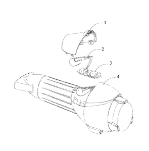
100061 Fig. l is
a structural schematic diagram of a touch device usable for a
hairdressing apparatus according to one or more embodiments disclosed herein.
100071 Fig. 2 is
a schematic diagram of the working principle of a touch device usable
-for a hairdressing apparatus according to one or more embodiments disclosed
herein.
[0008] Fig. 3 is
a schematic diagram of a functional control circuit according to one
or more embodiments disclosed herein.
10009j Fig. 4 is
a schematic diagram of a power circuit according to one or more
embodiments disclosed herein.
[0010] Fig. 5 is
a schematic diagram of an on-off control circuit according to one or
more embodiments disclosed herein.
[0011] Fig. 6 is
a schematic diagram of a circuit of a BS66F340-28 chip according to
one or more embodiments disclosed herein.
DETAILED DESCRIPTION
100121 in order
to enable those skilled in the art to better understand the technical
solution of one or more embodiments of the present invention, the description
is
provided below in combination with the accompanying drawings. In the
embodiments presented in this description, numerous specific details are set
forth in
order to provide a more thorough understanding of the present invention.
However, it
will be apparent to one of ordinary skill in the art that the present
invention may be
practiced without these specific details. In other instances, well-known
features have
not been described in detail to avoid obscuring the present invention.
100131 According
to embodiments of the present disclosure, a touch device usable for
a hairdressing apparatus may include a touch sensing shell, a FPC (Flexible
Printed
Circuit) board and a PCB (Printed Circuit Board), wherein the touch sensing
shell
may be mounted on the outer sUrface of the hairdressing apparatus. The FFC
board
may he attached to the touch sensing shell and may be mounted between the
touch
sensing shell and the hairdressing apparatus. The PCB may be connected with
the
FTC board by use of a lead and may be positioned inside the hairdressing
apparatus.
CA 03005326 2018-05-14
WO 2017/087101 PCT/US2016/056994
In one or more embodiments, the touch sensing shell may have a thickness
within the
range of 0.02 inches to 0.20 inches (about 0.5mra to 5mm).
[0014] The PCB may include a power circuit unit and an on-off control unit.
The
power circuit unit may be used for providing reliable and stable power for the
touch
device. The on-off control unit may be used for turning, oniturning off the
touch
device. In one or more embodiments, the on-off control unit includes an on-off
control circuit.
100151 A power circuit unit may include a power circuit, and the power
circuit may
include a power management chip. In one or more embodiments, the power circuit
may further include one or more capacitors, resistors, diodes, triodes, fuses,
and/or
inductors arranged in the power circuit with the power management chip. In one
or
more embodiments, the power management chip may be an MPI5OW chip,
[0016] The FPC board may include a central processing unit, a touch sensing
region
and a functional control unit, wherein the touch sensing region and the
fanctional
control unit are connected with the central processing unit, respectively. The
touch
sensing region may be used for sensing the touch actions of a user on the
touch
sensing shell. The functional control unit may be used for performing
corresponding
functions according to instructions emitted by the central processing unit. In
one or
more embodiments, the central processing unit may use a BS66F340-28 chip.
[0017[ In one or more embodiments, at least one touch sensing region may be
provided with a hair dressing apparatus, for example, by providing a FPC board
having at least one touch sensing region along the hair dressing apparatus.
[0018] A functional control unit may include one or more functional control
circuits,
whereby the functional control circuit may include a first current-limiting
resistor, a
first indicating LED lamp, a second indicating LED lamp and a third indicating
LED
lamp. One end of the first current-limiting resistor may be connected with the
positive
poles of the first indicating ILED lamp, the, second indicating LED lamp and
the third
indicating LED lamp, while the other end of the first current-limiting
resistor may be
connected to the central processing unit, The negative poles of the first
indicating
LED lamp, the second indicating LEE) lamp and the third indicating LED lamp,
may
be connected to the central processing unit respectively.
CA 03005326 2018-05-14
WO 2017/087101 PCT/US2016/056994
[00191 If the functional control unit includes a plurality of functional
control circuits,
the first current-limiting resistors of all the functional control circuits
may be
connected. with the central processing unit, respectively; the negative poles
of the first
indicating LED lamps of all the functional control circuits may be connected
together
and then connected with the central processing unit; the negative poles of the
second
indicating LED lamps of all the functional control circuits may he connected
together
and then connected with the central processing unit; and the negative poles of
the
third indicating LED lamps of all the functional control circuits may he
connected
together and then connected with the central processing unit.
[0020] In accordance with one or more embodiments of the present
disclosure, a FPC
board of a hair dressing apparatus may be attached to a touch sensing shell,
and
therefore, a user may operate the touch sensing shell to operate the hair
dressing
apparatus. The touch sensing shell may be capable of isolating a touch sensing
region
on the FPC board from the one or more fingers of the user, thus preventing the
user
from directly contacting the FPC board. In accordance with one or more
embodiments,
the touch sensing region and the functional control unit are arranged on the
FTC board.
and connected with the central processing unit The functional control unit
responds
with different functions to different touch actions performed on the touch
sensing
region, and thereby intelligent control of a hair dressing apparatus may be
realized.
[00211 Embodiments of the present disclosure are further described below
with
reference to the figures. Wherever possible, like or identical reference
numerals are
used in the figures to identify common or the same elements. The figures are
not
necessarily to scale and certain features and certain views of the figures may
be
shown exaggerated in scale for purposes of clarification.
[00221 As shown in Fig. 1, in accordance with one or more embodiments of
the
present invention, a touch device usable with a hairdressing apparatus is
provided.
The touch device may include a touch sensing shell 1, an FTC (Flexible Printed
Circuit) board 2 and a PCB (Printed Circuit Board) 3. The touch sensing shell
I may
be mounted on the outer surface of the hairdressing apparatus 4, The ITC board
2
may be attached to the touch sensing shell 1 and mounted between the touch
sensing
shell 1 and the hairdressing apparatus 4; the PCB 3 may be connected with the
FPC
board 2 by use of a lead and mounted inside the hairdressing apparatus 4.
4
CA 03005326 2018-05-14
WO 2017/087101 PCT/US2016/056994
[00231 Touch sensing shell 1 may be disposed on any surface of hairdressing
apparatus 4. In one or more embodiments, the touch sensing shell I may be
provided
on an upper barrel of a hairdressing apparatus 4. In other embodiments, touch
sensing
shell may be disposed on a handle of hairdressing apparatus 4.
[0024] As shown in 'Fig. 2, in one embodiment of the present invention, the
ITC
board 2 may include a central processing unit 21, a touch sensing region 22
and a
functional control unit 23, wherein the touch sensing region 22 and the
functional
control unit 23 may be connected with the central processing unit 21,
respectively.
The touch sensing region 22 may be used for sensing the touch actions of a
user on
the touch sensing shell 1. The functional control unit 23 may be used for
performing
corresponding functions according to instructions emitted by the central
processing
unit 21. The PCB 3 may include a power circuit unit 31 and an on-off control
unit 32.
The power circuit unit 31 may be used for providing reliable and stable power
for the
touch device. The on-off control unit 32 may be used for turning on/turning
off the
touch device.
[0025] As shown in Fig. 3, in one embodiment of the present invention, at
least one
touch sensing region 22 may be provided in the FPC board 2. In some
embodiments,
the central processing unit 21 may be included in a microcontroller, where the
microcontroller may be in communication with the touch sensing region(s) 22
and
functional control unit 23. In some embodiments, the microcontroller may be a
28 pin
BS66F340 chip, where the BS66F340-28 chip includes the central processing unit
21
and an LED driver, and where pins on the BS66F340-28 chip functioning for the
LED
driver may be connected to a light emitting interface that will output to a
screen (e.g.,
via the functional control unit 23). Each touch sensing region 22 may be
connected
with the corresponding pin of the BS66F340-28 chip respectively. For example,
as
shown in 'FIG. 3, the touch sensing region KEY 1 may be connected to the sixth
pin of
the BS66F340-28 chip and the touch sensing region KEY2 may be connected to the
fifth pin of the BS66F340-28 chip.
[0026] The functional control unit 23 may include one or more functional
control
circuits 231; the functional control circuit 231 includes a first current-
limiting resistor
231a, a first indicating LED lamp 231b, a second indicating LED lamp 231c and
a
third indicating LED lamp 231d. In the embodiment shown in FIG. 3, one end of
the
CA 03005326 2018-05-14
WO 2017/087101 PCT/US2016/056994
first current-limiting resistor 231a is connected with the positive poles of
the first
indicating LED lamp 23 lb, the second indicating LED lamp 231c and the third
indicating LED lamp 231d, While the other end of the first current-limiting
resistor
231a is connected with the central processing unit 21. The negative poles of
the first
indicating LED lamp 231b, the second indicating LED lamp 231c and the third
indicating LED lamp 231d are connected with the central processing unit 21. If
the
functional control unit 23 includes a plurality of functional control circuits
231, the
first current-limiting resistors 231a of all the functional control circuits
231 are
connected with the central processing unit 21, respectively; the negative
poles of the
first indicating LED lamps 231b of all the functional control circuits 231 are
connected together and then connected with the central processing unit 21; the
negative poles of the second indicating LED lamps 231c of all the functional
control
circuits 231 are connected together and then connected with the central
processing
unit 21; and the negative poles of the third indicating LED lamps 231d of all
the
functional control circuits 231 are connected together and then connected with
the
central processing unit 21.
100271 in embodiments where the functional control unit 23 is connected to
a
BS66F340-28 microcontrofier chip and includes more than one functional control
circuit 231, one end of the first current-limiting resistor 231a may be
connected with.
the positive poles of the first indicating LED lamp 231h, the second
indicating LED
lamp 231c and the third indicating LED lamp 231d, respectively, while the
other end
of the first current-limiting resistor 231a may be connected with the tenth
pin of the
BS661140-28 chip; and the negative poles of the first indicating LED lamp
231h, the
second indicating LED lamp 231c. and the third indicating LED lamp 231d may he
connected with the fourteenth pin, the thirteenth pin and the eleventh pin of
the
M6617340-28 chip, respectively. When the functional control unit 23 includes
four
functional control circuits 231, one end of the first current-limiting
resistor 231a of
each circuit may be connected with the positive poles of the first indicating
LED lamp
231b, the second indicating LED lamp 231c and the third indicating LED lamp
231d,
respectively, and the other end of the first current-limiting resistor 231a
may be
connected with the tenth pin, the eighth pin, the seventh pin and the second
pin of the
BS66F340-28 chip, respectively; the negative poles of the first indicating LED
lamps
CA 03005326 2018-05-14
WO 2017/087101 PCT/US2016/056994
23 lb of all the circuits may be connected and then connected with. the
fourteenth pin
of the BS60340-28 chip; the negative poles of the second indicating LED lamps
231c of all the functional control circuits 231 may be connected and then
connected
with the thirteenth pin of the BS66F340-28 chip; and the negative poles of the
third
indicating LED lamps 23 Id of all the functional control circuits 231 may be
connected and then connected with the eleventh pin of thellS66F340-28 chip.
[00281 When .the touch sensing region senses a touch action performed by a
user (the
touch actions include sliding, clicking and the like), the central processing
unit
identifies and responds to the action and then sends a responding instruction
to the
functional control circuit 231, and the functional control circuit 231 replies
to the
responding instruction. The result of the reply from the functional control
circuit 231
includes a relevant responding instruction driving the cOrresponding
indicating LED
lamp of the functional control circuit 231 to emit light. Different LED lamps
indicate
that different functions of the hairdressing apparatus are being performed.
For
instance, when the first functional control circuit 231 enables the first
indicating LED
lamp 231b, the second indicating LED lamp 231c and the third indicating LED
lamp
231d of the circuit all to emit light as responding to the instruction sent by
the central
processing unit, it may indicate the first gear of hot air and the first gear
of slow air on
the hair dressing apparatus.
[0029] As shown in Fig. 4õ the power circuit unit 31. in an embodiment of
the present
disclosure includes a power circuit. The power circuit includes a power
management
chip U I; the first pin and the fifth pin of the power management chip Ul are
connected with each other; the second pin of the power management chip Ul is
connected with one end of a capacitor C2, one end of a resistor R3 and one end
of a
resistor R4 in sequence; the other end of the resistor R4 is connected with
one end of
a capacitor C3 and the negative pole of a diode D4 respectively; the fourth
pin of the
power management chip Lil is connected with one end of a capacitor CI; the
other
end of the capacitor CI is connected with the other ends of the capacitor C2,
the
resistor R3 and the capacitor C3, one end of a coil L2 and the negative pole
of a diode
D5, respectively; the other end of the capacitor Cl is further connected with
the first
pin and the fifth pin of the power management chip 1.j1 , respectively; the
positive pole
of the diode D5 is connected with one end of an electrolytic capacitor EC3,
one end of
CA 03005326 2018-05-14
WO 2017/087101 PCT/US2016/056994
a. resistor R5 and one end of a capacitor C4, and grounded; the other end of
the coil
L2 is further connected with the positive pole of the diode D4, the other end
of the
electrolytic capacitor EC3, the other end of the resistor R5 and the other end
of the
capacitor C4; the other end of the coil L2 is further connected with the
negative pole
of an electrolytic capacitor EC1, the positive pole of a diode D2, the
negative pole of
a polar capacitor CX1, one end of a voltage dependent resistor R6, one end of
a
resistor R2 and one end. of a resistor R7 in sequence; the third pin of the
power
management chip UI is connected with the positive pole of the electrolytic
capacitor
ECI and one end of a coil LI respectively; the other end of the coil Li is
connected
with the negative pole of a diode .D3; the positive pole of the diode D3 is
connected.
with one end of a resistor R17; the other end of the resistor R17 is connected
with the
positive pole of a diode DI , the positive pole of a polar capacitor CXI, the
other end
of the voltage dependent resistor R6, one end of a resistor R1 and one end of
a fuse
Fl; the negative pole of the diode D1 is connected with the negative pole of
the diode
1)2; the other end of the resistor R1 is connected with the other end of the
resistor R2;
the other end of the fuse Ft and one end of the resistor R2 serve as power
input ends;
the other end of the resistor R7 is connected with one end of a resistor R9;
the other
end of the resistor R9 is connected with the negative pole of a diode 1)7 and
the base
of a triode QI, respectively; the positive pole of the diode D7 is grounded;
the
collector of the triode QI is connected in series with a resistor RIO; the
collector of
the triode QI serves as the power output end of the power circuit and are
connected
with the central processing unit 21; and the emitter of the triode Q1 is
grounded.
Specifically, in practical implementation, the input end of the power source
is
connected with an external power source, and the current of the external power
source
is rectified into high-voltage direct current via the diode D2, the coil Li
and the
electromagnetic capacitor EC I, and then the high-voltage direct current is
stepped
down by the power management chip Ul to provide low-voltage direct current for
the
touch device.
[0030] A.s shown in Fig. 5 and Fig, 6, the diagram of the on-off control
circuit and the
schematic diagram of the circuit of the BS66F340-28 chip of the central
processing
unit are displayed. The on-off control circuit is connected with the central
processing
unit via the ON/OFF end, and in embodiments where the central processing unit
is
8.
CA 03005326 2018-05-14
WO 2017/087101 PCT/US2016/056994
contained in a BS66F340-28 chip, the on-off control circuit may be connected
with
the ON/OFF pin of the BS66F340-28 chip. In order to ensure that the FPC board
is
capable of sensing the operation actions of the user when the user performs
the touch
operations on the touch sensing region, the touch sensing shell may be 0.5mm-
5mm
(0,02 in to 0..2 in) in thickness, including sub-ranges provided therein. For
example, a
touch sensing shell may have a thickness ranging from 0.7 mm to 4 mm, 0.9 mm
to 3
mm, or 1 to 2 mm. As long as the touch sensing shell is within the thickness
range,
the touch sensing region of the FPC circuit board may be capable of sensing
the
operation actions of the user without obstacles.
[0031] Unlike existing hair dressing apparatuses, the one or more
embodiments
presented herein may provide intelligent control of hair dressing apparatuses.
Different functions may be performed on the hair dressing apparatus in
response to
different touch actions performed on the touch sensing region, and thereby
intelligent
control is realized. Accordingly, the one or more embodiments presented herein
may
provide much needed alternatives to the mechanical switches and selectors
found on
conventional hair dressing apparatuses. The one or more embodiments of the
present
invention may provide a user with greater control of a hair dressing
apparatus, and
ultimately may provide the user with better overall hair styling results white
using a
hair dressing apparatus. Further, one or more embodiments disclosed in the
present
disclosure may overcome the difficulty in providing a touch sensing region on
a hair
dressing apparatus, which has limited space availability for incorporating
such a touch
sensing region,
[0032] While the present disclosure has been described with respect to a
limited
number of embodiments, those skilled in the art, having benefit of this
disclosure, will
appreciate that other embodiments may be devised which do not depart from the
scope of the disclosure as described herein. Accordingly, the scope of the
disclosure
should be limited only by the attached claims.
9