Note: Descriptions are shown in the official language in which they were submitted.
CHEST-MOUNTED SUPPORT DEVICE
CROSS-REFERENCES TO RELATED APPLICATIONS
This application claims the benefit of U.S. Provisional Patent Application
No. 62/085214, filed November 26, 2014, and U.S. Provisional Patent
Application
No. 62/146095, filed April 10, 2015.
BACKGROUND
People who work on their hands and knees often suffer great lower back, knee,
and
wrist pain from long hours of working in that position. Therefore, there
exists a need for a
support device for working on hands and knees for daily work and also for
people recovering
from an injury.
SUMMARY
This summary is provided to introduce a selection of concepts in a simplified
form that
are further described below in the Detailed Description. This summary is not
intended to
identify key features of the claimed subject matter, nor is it intended to be
used as an aid in
determining the scope of the claimed subject matter.
In one embodiment, a body support device comprises: a body attachment portion
configured for attaching the body support device to a body of a user, wherein
the body
attachment portion has a first side and a second side wherein the first side
is configured for
coupling with the body of the user and wherein the second side is configured
for facing away
from the body of the user, wherein the second side has a first end and a
second end, the body
attachment portion including a bumper extending from the body attachment
portion; a leg
comprising an elongate member having an elongate body having a central
longitudinal axis, a
proximal end and a distal end, a first side, and a second side, the leg
configured for coupling
with the body attachment portion, wherein the proximal end includes a
continuous first
stopping surface configured for contact with the body attachment portion, the
first stopping
surface having a first end at the first side of the leg and a second end at
the second side of the
leg, and wherein the distal end of the leg is configured to extend outwardly
from the body
attachment portion; and a coupling interface for hingedly coupling the leg to
the body
-1-
Date Recue/Date Received 2020-11-24
attachment portion, such that the leg is configured for hinging between
extended and retracted
positions relative to the body attachment portion within a pivot range between
0 degrees and
90 degrees from vertical in a single plane perpendicular to the body
attachment portion,
wherein the coupling interface is spaced from the first end and the second end
of the second
side of the body attachment portion, and wherein the bumper on the body
attachment portion
prevents movement of the leg beyond the retracted position, wherein the bumper
contacts the
leg only when the leg is in the retracted position.
In another embodiment, a body support device comprises: a body attachment
portion
for releasably attaching the body support device to a body of a user, wherein
the body
attachment portion has a first side and a second side wherein the first side
is configured for
coupling with the body of the user and wherein the second side is configured
for facing away
from the body of the user, wherein the second side has a first end and a
second end; a leg
comprising an elongate member having an elongate body having a proximal end,
and a distal
end configured for coupling with the body attachment portion, wherein the
proximal end is a
first stopping surface, and wherein the distal end is configured to extend
outwardly from the
body attachment portion and the body of the user; a coupling interface for
coupling the leg to
the body attachment portion, wherein the coupling interface includes a hinge
near to the first
stopping surface, such that the leg is hingedly coupled to the body attachment
portion and
configured for hinged movement between extended and retracted positions
relative to the body
attachment portion within a pivot range between 0 degrees and 90 degrees from
vertical in a
single plane perpendicular to the body attachment portion; a second stopping
surface on the
body attachment portion to opposingly contact the first stopping surface on
the proximal end
of the leg to restrict movement of the leg beyond the extended position; and a
bumper coupled
to the second side of the body attachment portion and extending outwardly from
the second
side of the body attachment portion to prevent movement of the leg beyond the
retracted
position, wherein the bumper is spaced from the hinge and wherein the bumper
contacts the
leg only when the leg is in the retracted position.
In another embodiment, a body support device comprises: a body attachment
portion
configured for attaching the body support device to a body of a user, wherein
the body
attachment portion has a first side and a second side wherein the first side
is configured for
-1 a-
Date Recue/Date Received 2020-11-24
coupling with the body of the user and wherein the second side is configured
for facing away
from the body of the user, wherein the second side has a first end and a
second end, the body
attachment portion including a bumper extending from the body attachment
portion; a leg
comprising an elongate member having an elongate body, a proximal end and a
distal end, a
first side and a second side, and a longitudinal axis, the leg configured for
coupling with the
body attachment portion, wherein the proximal end of the leg includes a
continuous first
stopping surface configured for contact with the body attachment portion, the
first stopping
surface having a first end at the first side of the leg and a second end at
the second side of the
leg, and wherein the distal end of the leg is configured to extend outwardly
from the body
attachment portion; a coupling interface configured for hinged coupling of the
leg to the body
attachment portion, wherein the coupling interface includes a hinge with first
and second
hinging portions, the first hinging portion attached to the body attachment
portion, the second
hinging portion attached to the leg, such that the leg is hingedly coupled to
the body
attachment portion and configured for hinging at a location spaced adjacent to
the second end
of the first stopping surface, the first and second hinging portions each
including one or more
knuckles, wherein the hinge is spaced from the first end and the second end of
the second side
of the body attachment portion, and wherein the bumper on the body attachment
portion
prevents movement of the leg beyond the retracted position, wherein the bumper
contacts the
leg only when the leg is in the retracted position.
In another embodiment, a body support device comprises: a body attachment
portion
configured for attaching the body support device to a body of a user, therein
the body
attachment portion has a first side and a second side, wherein the first side
is configured for
coupling with the body of the user and wherein the second side is configured
for facing away
from the body of the user, wherein the first side includes at least one
receiving channel; a leg
comprising an elongate member having an elongate body having a central
longitudinal axis,
the leg configured for coupling with the body attachment portion, the elongate
member
configured for hinged movement between extended and retracted positions; and a
coupling
interface for hingedly coupling the leg to the body attachment portion, such
that the leg is
configured for hinging between extended and retracted positions relative to
the body
-lb-
Date Recue/Date Received 2020-11-24
attachment portion, wherein the coupling interface is configured for slidably
releasable
attachment with the at least one receiving channel on the body attachment
portion.
In another embodiment, a body support device comprises: a body attachment
portion
configured for attaching the body support device to a body of a user, therein
the body
attachment portion has a first side and a second side, wherein the first side
is configured for
coupling with the body of the user and wherein the second side is configured
for facing away
from the body of the user, wherein the first side includes at least one
receiving channel; a leg
comprising an elongate member having an elongate body having a central
longitudinal axis,
the leg configured for coupling with the body attachment portion, the elongate
member
configured for hinged movement between extended and retracted positions; and a
coupling
interface for hingedly coupling the leg to the body attachment portion, such
that the leg is
configured for hinging between extended and retracted positions relative to
the body
attachment portion, wherein the coupling interface is configured for slidably
releasable
attachment with the at least one receiving channel on the body attachment
portion, wherein the
at least one receiving channel on the body attachment portion includes a
locking mechanism
configured to maintain the at least a portion of the coupling interface within
the at least one
receiving channel on the body attachment portion and to release the coupling
interface from
the at least one receiving channel when the locking mechanism is disengaged by
the user.
In another embodiment, a method of using a body support device includes:
attaching a
body attachment portion to a body of a user, the body attachment portion
having a first side
and a second side, wherein the first side is configured for coupling with the
body of the user
and wherein the second side is configured for facing away from the body of the
user, wherein
the first side includes at least one receiving channel; and releasably
coupling a leg assembly
with the body attachment portion, the leg assembly including an elongate
member having an
elongate body having a central longitudinal axis, the elongate member
configured for hinged
movement between extended and retracted positions, and the leg assembly
including a
coupling interface configured to allowing hinged movement between extended and
retracted
positions relative to the body attachment portion, wherein the leg assembly
releasably couples
with the body attaching portion by sliding at least a portion of the coupling
interface within the
at least one receiving channel on the body attachment portion.
-1c-
Date Recue/Date Received 2020-11-24
In another embodiment, a body support device comprises: a body attachment
portion
configured for attaching the body support device to a body of a user, wherein
the body
attachment portion has a first side and a second side wherein the first side
is configured for
coupling with the body of the user and wherein the second side is configured
for facing away
from the body of the user, wherein the second side has a first end and a
second end, the body
attachment portion including a bumper extending from the body attachment
portion; a leg
comprising an elongate member having an elongate body having a central
longitudinal axis, a
proximal end and a distal end, the leg configured for coupling with the body
attachment
portion at or near the proximal end, and wherein the distal end of the leg is
configured to
extend outwardly from the body attachment portion; a coupling interface for
hingedly
coupling the leg to the body attachment portion, such that the leg is
configured for hinging
between extended and retracted positions relative to the body attachment
portion within a
pivot range between 0 degrees and 90 degrees from vertical in a single plane
perpendicular to
the body attachment portion; and a lock for locking the elongate member in a
fixed position
within the pivot range relative to the body attachment portion.
In another embodiment, a body support device includes a chest plate, a body
strap
configured to couple the chest plate to a user, and a leg having a proximal
end and a distal end.
The proximal end is configured for releasably coupling with the chest plate
and wherein the
distal end is configured to extend outwardly from the chest plate and the body
of the user.
In one example, the body support device includes a coupling interface for
releasably
coupling the chest plate and the proximal end of the leg. In another example,
the leg when
coupled is configured for pivotal movement relative to the chest plate. In
another example,
the pivotal movement is in a pivot range between 0 degrees and 90 degrees from
horizontal
vertical in a single plane perpendicular to the chest plate or in a pivot
range between 5 degrees
and 85 degrees from vertical in a single plane perpendicular to the chest
plate. In another
example, the leg, when coupled to the chest plate, is configured in a fixed
position for no
movement relative to the chest plate. In another example, the leg is fixed at
one or more
positions having an angle in the range of 20 degrees to 90 degrees from
vertical in a single
plane perpendicular to the chest plate.
-1d-
Date Recue/Date Received 2020-11-24
CA 03005821 2018-05-18
WO 2016/085922 PCT/US2015/062313
In another example, the coupling interface is configured to hingedly couple
the
leg to the chest plate. In another example, the hinged coupling further
includes at least
one of a bumper or a stop to restrict movement of the leg. In another example,
the
coupling interface is a ball joint. In another example, the body support
device further
comprises a foot coupled to the distal end of the leg. In another example, the
foot is fixed
in position relative to the leg. In another example, the foot is rotatably
coupled to the
distal end of the leg. In another example, the foot has a bottom surface
selected from the
group consisting of a plate, a plate having curved sides, a concave plate, and
a concave
plate having a plurality of holes. In another example, the foot includes a
handle
configured to be grasped by a user when the foot is in contact with a surface.
In another example, the coupling interface is located such that a pivot axis
of the
coupling interface is located between about the center of the height of the
chest plate and
about three fourths of the distance from the bottom of the chest plate to the
top of the
chest plate. In another example, the chest plate includes a plurality of holes
for
breathability. In another example, the body strap is attachable to the chest
plate using at
least one strap attachment portion. In another example, the body support
device includes
a shoulder strap couplable to the chest plate and the body strap. In another
example, the
shoulder strap is couplable to the body strap in a plurality of locations. In
another
example, the body support device further includes one or more leg straps
coupled to one
or more of the chest plate or the body strap, and the one or more leg straps
are configured
to extend around one or more legs of a user. In another example, the body
support device
further includes a carrying device configured to be worn by a user and to be
coupled to
the leg when the leg is not coupled to the chest plate.
In another example, the chest plate includes a latchplate stability component
configured to receive at least a portion of the proximal end of the leg. In
another
example, the proximal end of the leg includes a latchplate configured to be
inserted into a
channel of the latchplate stability component of the chest plate. In another
example, the
latchplate is configured to be inserted into the channel upward vertically and
the channel
is configured to provide a hard stop for the upward vertical insertion of the
latchplate. In
another example, the latchplate stability component and the chest plate are
made from
one or more of a plastic material or a composite material and the latchplate
stability
component and the chest plate are integrally formed together.
-2-
CA 03005821 2018-05-18
WO 2016/085922 PCT/US2015/062313
DESCRIPTION OF THE DRAWINGS
The foregoing aspects and many of the attendant advantages of the disclosed
embodiments will become more readily appreciated as the same become better
understood by reference to the following detailed description, when taken in
conjunction
with the accompanying drawings, wherein:
FIGURE 1 depicts an embodiment of a user in an upright position and using a
chest-mounted support device, in accordance with the embodiments disclosed
herein;
FIGURE 2 depicts a side view of the user and the support device depicted in
FIGURE 1, with a leg of the support device extending out at an angle of about
90 degrees
from vertical;
FIGURE 3 depicts a side view of the user and the support device depicted in
FIGURE 1, with a leg of the support device extending out at an angle of about
5 degrees
from vertical;
FIGURE 4 depicts a side view of the user and the support device depicted in
FIGURE 1, with the user in a kneeling position and the leg extending
approximately
perpendicular to a chest plate of the support device;
FIGURE 5 depicts a front perspective view of the support device depicted in
FIGURE 1 without the user;
FIGURE 6 depicts a back perspective view of the support device depicted in
FIGURE 1 without the user;
FIGURES 7 and 8 depict partial views of the leg and a coupling mechanism of
the
support device depicted in FIGURE 1;
FIGURES 9 and 10 depict an embodiment of coupling the leg to the chest plate
of
the support device depicted in FIGURE 1;
FIGURE 11 depicts a front view of a front of the support device depicted in
FIGURE 1 with the leg pointing at an angle of 0 degrees from vertical.
FIGURE 12 depicts an embodiment of a leg carrying device configured to carry a
detachable leg of a support device when the leg is detached from a chest
plate;
FIGURES 13 to 18 depict an embodiment of a detachable leg with an angle
stabilization mechanism that can be used with the embodiments of support
devices
described herein; and
FIGURES 19 to 20 depict an embodiment of a foot, usable with the embodiments
of support devices described herein, that has a concave surface and a handle.
-3-
CA 03005821 2018-05-18
WO 2016/085922 PCT/US2015/062313
DETAILED DESCRIPTION
Embodiments of the present disclosure are directed to a chest-mounted support
device. In accordance with one embodiment of the present disclosure, a chest-
mounted
support device 20 can be seen in FIGURES 1-11. The support device 20 includes
a chest
plate 22, a body strap 24 configured to couple the chest plate 22 to a user U,
and a leg 26
have a proximal end 30 and a distal end 32. The proximal end 30 is coupled to
the chest
plate 22 and the distal end 32 is configured to extend outwardly from the
chest plate 22
and the body of the user U.
The support device 20 is designed and configured to provide support of a
user's
upper body weight to alleviate stress and strain from the weight of the upper
torso on the
lower back, spine, knees, and muscles as well as evenly distributing body
weight to at
least three points when in a kneeling position: two knees and the chest (see
FIGURE 4).
The support device 20 also frees up both hands for working. The support device
20 can
also be used in an upright position, for example, to gain support from a wall
(see
FIGURE 2). In general, the support device 20 helps alleviate the effects of
unnatural
weight loads on a user's body due to work or other demands.
The support device 20 may be used in any of a number of working applications
including, but not limited to, flooring, painting, plumbing, carpentry,
electrical, tile and
masonry, mechanics, gardening, home and commercial cleaning, auto detailing,
factory
line work, agricultural work (e.g., harvesting), etc.
Referring to FIGURE 1, the chest plate 22 is a shield or plate having a first
side 34 and a second side 36. The first side 34 is designed for placement
against the body
of the user. The second side 36 is an outwardly extending side. In one
embodiment of
the present disclosure, the first side 34 may include a padding material to
provide comfort
to the user. In one example, the padding material includes closed cell, high
density foam
with a thickness in a range from about 0.5 inches to about 2.0 inches. The
first side 34
may be ergonomically conformed to the user's body. For example, the first side
34 may
be contoured to fit securing against the contours of a human body. Likewise,
the second
side 36 may also be contoured to have a substantially uniform thickness along
the cross
section of the chest portion.
The second side 36 may be configured from a rigid material to provide
structure
to the chest-mounted support device 20. For example, the second side 36 may be
configured from a rigid plastic or metal material.
-4-
CA 03005821 2018-05-18
WO 2016/085922 PCT/US2015/062313
The chest plate 22 is sized to provide body support to a user U, whether the
user U
is in a standing, angled, or full horizontal position. In the illustrated
embodiment, the
chest plate 22 is designed to extend across most of the width of a user's
chest and to have
a near center point aligned with the sternum of the user. In some embodiments
of the
present disclosure, the chest plate 22 may be sized larger to provide
additional body
support for a user. For example, in a cement work application, the user U may
want to
rest his full body weight on the support device. In this application, a larger
chest plate 22
may be advantageous. In some embodiments of the present disclosure, the chest
plate 22
and/or the padding material on the first side 34 of the chest plate us
contoured based on a
gender of a user (e.g., based on female anatomy or male anatomy).
The chest plate 22 may have a series of holes 38 extending through the first
side 34 and the second side 36 to provide breathability and comfort for the
user U.
A body attachment portion 28 attaches the chest plate 22 to the user's body.
In the
illustrated embodiment, the body attachment portion 28 includes a body strap
24 used to
wrap around the user's torso and attach the chest plate 22 to the user's body.
The body
strap 24 may be a flexible fabric strap for comfort and ease of use. The body
strap 24
may be configured to have an adjustable length. Such adjustment may be
achieved by
belt buckles, hook and loop fasteners, clamp-type fasteners, or any other
suitable
adjustment mechanism. In the illustrated embodiment, the body attachment
portion 28
also includes a shoulder strap 40 used to provide additional stability of the
chest plate 22
to the user's body. The chest plate 22 includes a hook fastener 80 and the
body strap
includes a plurality of loops 82. The hook fastener 80 is configured to be
fastened to one
of the plurality of loops 82 at any given time. The user U may fasten the hook
fastener 80
to a particular one of the plurality of loops 82 depending on the size of the
user's chest.
The shoulder strap 40 may carry little or no load during use of the support
device 20.
However, the shoulder strap 40 can provide support to the support device 20
while the
user is putting on the support device 20 and/or when the user is in a sitting
position.
The body strap 24 is attached to the chest plate 22 by a strap attachment
portion 42. In the illustrated embodiment, the strap attachment portion 42
includes two
rods positioned outwardly from the second side 36 of the chest plate 22. The
rods are
oriented substantially vertical when the user U is standing vertically (see
FIGURE 2).
One end of the body strap 24 slides between a first rod and the second side 36
of the chest
plate 22, wraps around the first rod, and is secured to another portion of the
body
-5-
CA 03005821 2018-05-18
WO 2016/085922 PCT/US2015/062313
strap 24. The other end of the body strap 24 is secured around a second rod in
similar
fashion. The rods provide points of leverage that allow the body strap 24 to
be pulled
tightly to create a snug fit of the chest plate 22 against the user's body.
The rods are
positioned outwardly from the second side 36 of the chest plate 22 to provide
leverage for
the user when fitting the body strap 24 to the user's body.
Although the strap attachment portion 42 is shown as two rods, the strap
attachment portion 42 may include just one rod. In such an embodiment, one end
of the
body strap 24 may be fixed to one side of the chest plate 22 and the other end
of the body
strap is capable of adjustment to the single rod on the other side of the
chest plate 22.
Other embodiments of body attachment portions are also within the scope of the
present
disclosure. For example, the body strap may be received in longitudinal slots
extending
through the chest plate.
The shoulder strap 40 may be used to help maintain the positioning of the
chest
plate 22 on the user's body. In the illustrated embodiment, one end of the
shoulder
strap 40 is attached to the second side 36 of the chest plate 22 and the other
end of the
shoulder strap 40 is attached to the body strap 24. In one embodiment, the
point at which
the shoulder strap 40 attached to the body strap 24 is adjustable along the
length of the
body strap 24 to accommodate users of different sizes.
In another embodiment of the body attachment portion 28, one or more leg
straps 86 may be used to further maintain the positioning of the chest plate
22 on the
user's body. The one or more leg straps 86 are coupled to the chest plate 22
and/or the
body strap 24 and extend around the tops of the user's legs. In one example,
the one or
more leg straps 86 are configured to transfer some or all of the load from the
chest
plate 22 to the user's legs. This arrangement can reduce the load on the
user's spine
and/or lower back. In another example, when a user is using the support device
20 in a
horizontal position, the one or more leg straps 86 can act as a governor by
pulling taught
when the user leans forward a certain distance. The user can interpret the one
or more leg
straps 86 pulling taught as a warning that the user is getting too far forward
over the
support device 20 and return back to a safe position before the user falls
forward over the
top of the support device 20. In another example, when a user is using the
support
device 20 in a standing position (e.g., when performing a standing assembly
line job),
most all of the load from a user is carried through the one or more leg straps
86. In one
-6-
CA 03005821 2018-05-18
WO 2016/085922 PCT/US2015/062313
particular example, when the user is leaning on a table and the user's foot
touches the
table, the load would be carried by the one or more leg straps 86.
The leg 26 can be configured to extend outwardly from the chest plate 22 and,
when worn by a user, from the body of the user U. In the illustrated
embodiment, the
leg 26 is a telescoping leg that permits the length of the leg 26 to be
adjusted. However,
the leg 26 could also have a fixed length. One benefit to the telescoping leg
is that it
permits the user U to adjust the length of the leg, as may be preferable
depending on the
particular use of the support device 20. For example, the user U may prefer a
one length
of the leg 26 when standing vertically with the leg 26 against a wall (as
illustrated in
FIGURE 2) and a different length when positioned horizontally with the leg 26
braced
against the ground.
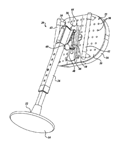
In the illustrated embodiment of FIGURE 5, the leg 26 has a coupling interface
44
configured to couple the leg 26 to the chest plate 22 and to permit the leg 26
to pivot
when coupled to the chest plate 22. In one embodiment, when the leg 26 is
coupled to the
chest plate 22 and the user U is standing vertically (see FIGURE 2), the
coupling
interface 44 permits the leg 26 to pivot about an axis that is substantially
horizontal and
substantially parallel to the chest plate 22. In other words, the coupling
interface 44
permits the leg 26 to pivot in a plane that is substantially perpendicular to
the chest plate
22.
In one embodiment, the leg 26 is configured to pivot in a pivot range. In one
embodiment, the pivot range is between 0 degrees from vertical (i.e., with the
leg 26
pointed directly down when the user is standing vertically) and about 90
degrees from
horizontal and about 90 degrees from vertical (i.e., the position shown in
FIGURE 2 with
the leg 26 substantially perpendicular to the chest plate 22). In another
embodiment, the
range is between about 5 degrees from vertical (i.e., the position shown in
FIGURE 3
with the leg 26 not entirely vertical) and about 85 degrees from vertical.
Stops, described
in greater detail below, are used to control the pivot range of the leg 26.
During usage of
the support device 20, the hinged movement of the leg 26 to the chest plate 22
allows for
some rocking motion of the leg 26 when it is supporting the user. Such rocking
motion
allows the user to move constantly while being supported by the leg. In one
embodiment,
the leg 26 is coupled to the chest plate 22 via a ball joint.
In some embodiments, the coupling interface 44 is configured such that leg 26
and/or the pivot axis between the leg 26 and the chest plate 22 are in
particular locations.
-7-
CA 03005821 2018-05-18
WO 2016/085922 PCT/US2015/062313
In one embodiment, the coupling interface 44 is configured such that the leg
26 is
horizontally centered on the chest plate 22. In another embodiment, the
coupling
interface 44 is configured such that the pivot axis is vertically centered on
the chest plate.
In yet another embodiment, the coupling interface 44 is configured such that
the pivot
axis is located vertically at a position between the center of the chest plate
and three
fourths of the distance from the bottom of the chest plate 22 to the top of
the chest
plate 22. Locating the pivot axis vertically above the center of the chest
plate 22 may
help avoid the user in a kneeling position from falling face-first over the
top of the leg 26.
In the illustrated embodiment, the coupling interface 44 includes a latchplate
46
that is configured to interact with a releasable buckle 48. In one embodiment,
the
releasable buckle 48 is biased to an extended position (as shown in FIGURE 5),
but is
capable of being pushed back into the chest plate under certain conditions.
For example,
as the latchplate 46 is moved vertically upward into the releasable buckle 48,
the
latchplate 46 may cause the releaseable buckle 48 to retract until the
latchplate 46 is
above the releasable buckle 48, at which point the releasable buckle 48 holds
the
latchplate 46 in place. In another embodiment, the releasable buckle 48 is
similar to a
seatbelt buckle that receives the latchplate 46. Any number of other
embodiments of
releasable buckle 48 can be used. The releasable buckle 48 may include a
release
mechanism (e.g., a quick release mechanism) that, when activated, causes the
releasable
buckle 48 to retract and permits the latchplate 46 to be uncoupled from the
releasable
buckle 48. In some embodiments, the user may use a single hand to release the
latchplate 46 from the releasable buckle 48. While the illustrated embodiment
includes a
latchplate 46 and a releasable buckle 48, other coupling mechanisms are usable
to
releasably couple the leg 26 to the chest plate 22 and within the scope of the
present
disclosure.
In the illustrated embodiment, the chest plate 22 incudes a latchplate
stability
component 50. To couple the leg 26 to the chest plate 22, the latchplate 46 is
inserted
through the latchplate stability component 50 until the latchplate 46 is
coupled to the
releasable buckle 48. In the illustrated embodiment, the latchplate stability
component 50
includes a channel through which the latchplate 46 is inserted (see FIGURES 9
and 10).
In another embodiment, the latchplate stability component 50 includes a series
of slots or
a series of slots and channels through which the latchplate 46 is inserted.
The latchplate
stability component 50 provides lateral stability to the leg 26 when coupled
to the chest
-8-
CA 03005821 2018-05-18
WO 2016/085922 PCT/US2015/062313
plate 22 to prevent movement and/or rotation of the leg 26 (aside from any
intended
pivoting of the leg 26 in the pivot range).
In some embodiments, the chest plate 22 and the latchplate stability component
50
are made from rigid materials, such as a metal material, a hard plastic
material, and/or a
composite material. In some embodiments, the latchplate stability component 50
is
fixedly attached to the chest plate 22. For example, in the case where the
chest plate 22
and the latchplate stability component 50 are made from metal materials, the
latchplate
stability component 50 may be welded to the chest plate 22. In some
embodiments, the
latchplate stability component 50 is integrally formed with the chest plate
22. For
example, in the case where the chest plate 22 and the latchplate stability
component 50
are made from moldable plastic and/or composite materials, latchplate
stability
component 50 can be formed with the chest plate 22. In some embodiments, the
latchplate stability component 50 is removably attached to the chest plate 22.
For
example, the latchplate stability component 50 may be attached to the chest
plate 22
using fasteners, such as screws, bolts, rivets, and the like.
In the illustrated embodiments, the latchplate 46 is inserted into the channel
of the
latchplate stability component 50 vertically and the channel provides a hard
stop for the
upward vertical movement of the latchplate 46. This hard stop acts as a safety
feature as
any accidental or unintended retraction of the buckle 48 will merely allow the
leg 26 to
fall downward out of the chestplate. In other configurations, such as where
the
latchplate 46 is configured to be inserted downwardly vertical into the
latchplate stability
component 50, the accidental or unintended retraction of the buckle 48 allows
the leg 26
to slide upwardly and hit the upper chest or face area of the user. With the
force exerted
by the user's body on the leg 26, such an accidental or unintended movement of
the leg 26
upward could cause serious injury or death to the user.
In the illustrated embodiment, the coupling interface 44 also includes a
bumper 52
that acts as a stop. The bumper 52 is configured to prevent the leg 26 from
rotating
outside of the pivot range. In the embodiment depicted in FIGURE 8, the bumper
52 is
configured to contact a portion of the coupling interface 44 at a particular
point of
rotation of the coupling interface 44. In one example, the contact between the
bumper 52
and the latchplate 46 defines the lowest point at which the leg 26 can rotate
(e.g., the
point depicted in FIGURE 3). In one embodiment, when the user U is standing
vertically,
the bumper 52 can prevent the leg 26 from rotating down until the leg 26 is
vertical.
-9-
CA 03005821 2018-05-18
WO 2016/085922 PCT/US2015/062313
Preventing the leg 26 from rotating down until the leg 26 is vertical can help
ensure that
the leg 26 does not contact the lower body of the user U, thus avoiding injury
to the lower
body of the user U.
The bumper 52 can also provide the ability for the user U to quickly push out
(or "shoot") the leg 26. From the position depicted in FIGURE 3, the user U
may move
to push the chest plate 22 out quickly. The interaction of the bumper 52 on
the portion of
the coupling interface 44 coupled to the leg 26 causes the leg 26 to quickly
shoot out. As
the leg 26 shoots out, the user U may move such that the distal end 32 or the
foot 54
touches a surface (e.g., a wall or the ground) at a desired position. This
ability to shoot
the leg 26 adds to the safety of the support device 20 because the user U can
quickly set
the leg 26 if necessary and it adds to the convenience of the support device
26 because it
reduces the amount of time to set up the support device 20. In some
embodiments, the
bumper 52 is configured from a rigid material (e.g., a metal material or a
hard plastic
material) or a semi-rigid material (e.g., an elastomeric material). In some
embodiments,
the user is able to feel the point at which the leg 26 hits the bumper 52 and
the bumper 52
acts as a predictable governor for the user. In some embodiments, when the
user is
working horizontally, the bumper 52 provides a resistance point that helps a
user prevent
the user's face from hitting ground.
In another embodiment, the proximal end 30 of the leg 26 may be configured to
contact a stop 56 on the chest support device to prevent the leg 26 from
rotating higher
than the pivot range. For example, when the leg 26 is substantially
perpendicular to the
chest plate 22 (as shown in FIGURE 2), the proximal end 30 of the leg 26 can
contact the
stop 56 and prevent the leg 26 from rotating any further. Preventing the leg
26 from
rotating beyond the horizontal position shown in FIGURE 2 can help ensure that
the
leg 26 does not contact the upper body of the user U, thus avoiding injury to
the upper
body of the user U. In one embodiment, the stop 56 is formed as a part of the
chest
plate 22 and/or the latchplate stability component 50. In another embodiment,
the stop 56
is formed from a rigid material, such as a metal material or a hard plastic
material.
In some embodiments, the support device 20 also includes a foot 54 attached to
the distal end 32 of the leg 26. The foot 54 can be configured from a semi-
rigid material,
such as rubber, that protects the distal end 32 of the leg 26 and resists
movement of the
distal end 32 of the leg 26 against a surface (e.g., a wall or the ground). In
the illustrated
embodiment, the foot 54 is substantially larger than the distal end 32 of the
leg 26. Such
-10-
CA 03005821 2018-05-18
WO 2016/085922 PCT/US2015/062313
an embodiment can distribute the force exerted by the user's weight over a
large area and
protect both the leg 26 and the surface against which the foot 54 is in
contact. In
addition, in the illustrated embodiment, the foot 54 is concave, allowing the
foot 54 to roll
somewhat against a surface as the user U adjusts the user's position and/or
weight
distribution. In another embodiment that is not depicted, the foot 54 is
similar in size to
the distal end 32 of the leg 26. For example, the foot 54 can be similar in
size to the foot
of a crutch or cane. In some embodiments, the diameter of the foot is in a
range from
about 1 inch (e.g., about the size of a crutch foot) to about 8 inches. In
other
embodiments, the diameter of the foot is about 4 inches or about 6 inches.
In another embodiment, as depicted in FIGURES 19 and 20, the foot 54 has a
concave surface 72. A concave surface 72 may be advantageous in certain
circumstances, such as when the foot 54 is placed against a soft surface, such
as
semi-cured cement. Such a concave surface 72 may minimize any marks or
cavities in
the finished concrete. In one example, the convex surface of the foot 54 has a
plurality of
holes 74. The plurality of holes 74 allow air to pass in and out of the convex
area of the
foot 54 such that area between the foot 54 and the surface does not have
negative pressure
(i.e., to prevent the convex area of the foot 54 from acting as a suction
cup). In the
illustrated embodiment, the foot 54 includes a handle 84. The handle 84 allows
the user
to twist the foot 54 as it is being lifted up from a surface to further
prevent a negative
pressure suction. The handle 84 also provides the user with a leverage point
to hold
while the user is working (e.g., while the user is finishing concrete in the
position
depicted in FIGURE 4). The handle 84 also allows the user to hold the entire
detachable
leg when the detachable leg is uncoupled from the chest plate.
In some embodiments, such as in the illustrated embodiment, the foot 54 is
fixed
to the leg 26 such that any rotation of the leg 26 will cause a corresponding
rotation of the
foot 54. In another embodiment, the foot 54 is coupled to the distal end 32 of
the leg 26
via a hinge or joint, such as a ball joint 76. Such a hinge or joint may give
the user U a
greater range of motion while using the support device 20. However, the
greater range of
motion may also result in less stability. The range of motion allowed by the
hinge or
joint may be limited (e.g., using stops to limit the range of possible angles
of the hinge or
joint) to give better stability than with unlimited range of motion.
One benefit of the ability to decouple the leg 26 from the chest plate 22 is
that the
user U can remove the leg 26 from the chest plate 22 without having to remove
the entire
-11-
CA 03005821 2018-05-18
WO 2016/085922 PCT/US2015/062313
support device 20. For example, the user U may use the support device 20 at
one location
and then move to another location to use the support device 20. It may be
desirable to
move from one location to another without the leg 26 attached to the user's
chest.
However, it may also be desirable not to remove the chest plate 22 from the
user's chest
merely to move from one location to another. In such a case, the user may
remove the
leg 26 from the chest plate 22 at the first location, move to the second
location with the
chest plate 22 still attached to the user's chest, and then couple the leg 26
to the chest
plate 22 at the second location.
Another example of a benefit of a leg 26 that decouples from the chest plate
22 is
that multiple different legs may be used with the same chest plate 22. For
example, the
user may prefer a particular characteristic of the leg 26 when performing one
type of
work (e.g., finishing concrete) and a different characteristic of the leg 26
when
performing another type of work (e.g., laying tile). A characteristic of the
leg 26 can be
one or more of a specific length of the leg 26, a particular foot 54 on the
distal end 32 of
the leg, a particular pivot range of the foot 54 with respect to the leg 26,
and so forth.
The user may have a different leg for different types of work that the user
performs and
use the different legs with the same chest plate 22 interchangeably. Thus, the
user can
use the same chest plate 22 and couple different legs to the chest plate 22
depending on
the type of work that the user will be performing. A user can couple one leg
to the chest
plate 22 to perform one task, decouple that leg from the chest plate 22, and
couple
another leg to the chest plate 22 to perform another task. The ability to
continue wearing
the same chest plate 22 when switching legs and/or types of work can save time
and add
to the overall convenience of the support device 20 to the user.
FIGURE 12 depicts an embodiment of a leg carrying device 58 that can be used
to
carry the leg 26 when it is removed from the chest plate 22. The leg carrying
device 58 is
configured to receive a knob 60 located on the leg 26. The knob 60 can be
inserted
through a channel in the leg carrying device 58. The leg carrying device 58
permits the
leg 26 to rotate about the knob 60. This provides a natural movement of the
leg 26 when
the user is performing certain activities, such as walking. The leg carrying
device 58 can
optionally include a buckle mechanism that prevents unintended removal of the
leg 26
from the leg carrying device. The buckle mechanism also prevents unintended
damage as
a result of the leg 26 being unintentionally removed from the buckle
mechanism, such
preventing damage to work areas (e.g., airplane floors during assembly),
preventing the
-12-
CA 03005821 2018-05-18
WO 2016/085922 PCT/US2015/062313
leg 26 from falling from high locations (e.g., from hitting people or
equipment when the
user is working at heights), or preventing any other type of damage that could
be caused
by the leg 26 being loose.
In another example, the user U may use the leg 26 for support against a wall,
but
.. then need to perform other work that does not benefit from use of the leg
26. In this case,
the user may remove the leg 26 from the chest plate 22 and couple the leg 26
to the leg
carrying device 58 while performing the work that does not benefit from use of
the
leg 26. The user U can continue to wear the chest plate 22 while performing
the other
work and then later couple the leg 26 back to the chest plate 22 when the user
U again
.. desires to use the leg 26.
In one embodiment, as shown in FIGURES 13-18, the leg 26 includes an angle
stabilization mechanism 62 configured to limit or prevent pivoting of the leg
26 with
respect to the chest plate 22. The angle stabilization mechanism 62 includes a
latchplate 64 hingedly coupled to the chest plate 22 and a channel 66 fixed to
the leg 26.
In some embodiments, the latchplate 64 includes a number of latch points 68.
In the
illustrated embodiments, the latch points 68 are in the form of three holes in
the
latchplate 64. In one embodiment, the channel 66 includes a releasable buckle
70 that is
configured to selectively engage one of the latch points 68.
In one example of operation of the angle stabilization mechanism 62,
latchplate 46 is slid from the point shown in FIGURE 13 into the latchplate
stability
component 50 until the latchplate 46 is coupled to the releasable buckle 48 in
the point
shown in FIGURE 14. The latchplate 64 and the leg 26 are then rotated from the
point
depicted in FIGURE 14 to the point depicted in FIGURE 15. The latchplate 64 is
too
long to be inserted into channel 66 until it reaches the point depicted in
FIGURE 15. At
that point, the latchplate 64 is capable of being inserted into the channel
66.
With the latchplate 64 inserted into the channel 66, the latchplate 64 and the
leg 26 are rotated back to the point depicted in FIGURE 16 where the
releasable
buckle 70 engages a first latch point 68 on the latchplate 64. The engagement
of the
releasable buckle 70 and the first latch point 68 substantially prevents
rotation of the
leg 26 with respect to the chest plate 22. In the embodiment shown in FIGURE
16, the
leg 26 is substantially perpendicular to the chest plate 22.
In the case where the latchplate 64 includes multiple latch points 68, as in
the
illustrated embodiment, the releasable buckle 70 can be disengaged from the
first latch
-13-
CA 03005821 2018-05-18
WO 2016/085922 PCT/US2015/062313
point 68 and the latchplate 64 and the leg 26 can be further rotated to the
point depicted in
FIGURE 17 where the releasable buckle 70 engages a second latch point 68 on
the
latchplate 64. The engagement of the releasable buckle 70 and the second latch
point 68
substantially prevents rotation of the leg 26 with respect to the chest plate
22. In the
embodiment shown in FIGURE 17, the leg 26 is not perpendicular to the chest
plate 22.
In one example, in the arrangement shown in FIGURE 17, the leg 26 is an angle
of about
55 degrees with respect to the chest plate. The releasable buckle 70 can then
be
disengaged from the second latch point 68 and the latchplate 64 and the leg 26
can be
further rotated to the point depicted in FIGURE 18 where the releasable buckle
70
engages a third latch point 68 on the latchplate 64. The engagement of the
releasable
buckle 70 and the third latch point 68 substantially prevents rotation of the
leg 26 with
respect to the chest plate 22. In the embodiment shown in FIGURE 18, the leg
26 is not
perpendicular to the chest plate 22. In one example, in the arrangement shown
in
FIGURE 17, the leg 26 is at an angle of about 20 degrees with respect to the
chest plate.
In one embodiment, the leg 26 in FIGURE 18 is at an angle of about 60 degrees
from vertical. In another embodiment, the angle stabilization mechanism 62 is
configured to fix the leg 26 with respect to the chest plate 22 at one or more
positions
having an angle in the range from about 20 degrees to about 90 degrees from
vertical in a
single plane perpendicular to the chest plate 22.
Other embodiments of angle stabilization mechanisms, beyond the angle
stabilization mechanism 62 depicted in FIGURES 14-18, can be used to limit or
prevent
pivoting of the leg 26 with respect to the chest plate 22.
As described above, the leg 26 may pivot with respect to each of the chest
plate 22 and the foot 54. In some embodiments, the leg 26 may pivot freely
(e.g., in the
case of a ball joint or a hinge without stops) or rotation of the leg 26 may
be limited (e.g.,
with the use of stops). As also described above, rotational movements of the
leg 26 may
be fixed with respect to each of the chest plate 22 and the foot 54 (e.g.,
with a fixed foot
or with the use of an angle stabilization mechanism). During use of the
support
device 20, and combination of pivoting and/or fixed ends of the leg 26 are
possible. In
one example, the proximal end 30 of the leg 26 is fixed with respect to the
chest plate 22
and the distal end 32 of the leg 26 is fixed with respect to the foot 54. In
another
example, the proximal end 30 of the leg 26 is pivotable with respect to the
chest plate 22
and the distal end 32 of the leg 26 is fixed with respect to the foot 54. In
another
-14-
CA 03005821 2018-05-18
WO 2016/085922 PCT/US2015/062313
example, the proximal end 30 of the leg 26 is fixed with respect to the chest
plate 22 and
the distal end 32 of the leg 26 is pivotable with respect to the foot 54. In
yet another
example, the proximal end 30 of the leg 26 is pivotable with respect to the
chest plate 22
and the distal end 32 of the leg 26 is pivotable with respect to the foot 54.
While illustrative embodiments have been illustrated and described, it will be
appreciated that various changes can be made therein without departing from
the spirit
and scope of the claimed subject matter.
The detailed description set forth herein in connection with the drawings is
intended as a description of various embodiments of the disclosed subject
matter and is
not intended to represent the only embodiments. Each embodiment described in
this
disclosure is provided merely as an example or illustration and should not be
construed as
preferred or advantageous over other embodiments. The illustrative examples
provided
herein are not intended to be exhaustive or to limit the claimed subject
matter to the
precise forms disclosed.
-15-