Note: Descriptions are shown in the official language in which they were submitted.
CA 03006006 2018-05-23
WO 2017/114744
PCT/EP2016/082351
- 1 -
AEROSOL GENERATING ARTICLE INCLUDING A HEAT-CONDUCTING ELEMENT AND A
SURFACE TREATMENT
The present invention relates to an aerosol generating article comprising a
heat source,
an aerosol-forming substrate in thermal communication with the heat source and
a heat-
conducting component provided around at least a portion of the aerosol-forming
substrate and
comprising a surface coating. In some examples, the heat-conducting component
comprises
two or more heat-conducting elements.
A number of smoking articles in which tobacco is heated rather than combusted
have
been proposed in the art. One aim of such 'heated' smoking articles is to
reduce known harmful
smoke constituents of the type produced by the combustion and pyrolytic
degradation of
tobacco in conventional cigarettes. In one known type of heated smoking
article, an aerosol is
generated by the transfer of heat from a combustible heat source to an aerosol-
forming
substrate located downstream of the combustible heat source. During smoking,
volatile
compounds are released from the aerosol-forming substrate by heat transfer
from the
combustible heat source and entrained in air drawn through the smoking
article. As the
released compounds cool, they condense to form an aerosol that is inhaled by
the user.
Typically, air is drawn into such known heated smoking articles through one or
more airflow
channels provided through the combustible heat source and heat transfer from
the combustible
heat source to the aerosol-forming substrate occurs by convection and
conduction.
For example, WO-A-2009/022232 discloses a smoking article comprising a
combustible
heat source, an aerosol-forming substrate downstream of the combustible heat
source, and a
heat-conducting element around and in contact with a rear portion of the
combustible heat
source and an adjacent front portion of the aerosol-forming substrate.
The heat-conducting element in the smoking article of WO-A-2009/022232
transfers the
heat generated during combustion of the heat source to the aerosol-forming
substrate via
conduction. The heat drain exerted by the conductive heat transfer
significantly lowers the
temperature of the rear portion of the combustible heat source so that the
temperature of the
rear portion is retained significantly below its self-ignition temperature.
In aerosol generating articles in which an aerosol-forming substrate is
heated, for
example smoking articles in which tobacco is heated, the temperature attained
in the aerosol-
forming substrate has a significant impact on the ability to generate a
sensorially acceptable
aerosol. It is typically desirable to maintain the temperature of the aerosol-
forming substrate
within a certain range in order to optimise the aerosol delivery to the user.
In some cases,
radiative heat losses from the outer surface of the heat-conducting element
may cause the
temperature of the combustible heat source or the aerosol-forming substrate to
drop outside of
the desired range, thereby impacting the performance of the smoking article.
If the temperature
CA 03006006 2018-05-23
WO 2017/114744
PCT/EP2016/082351
- 2 -
of the aerosol-forming substrate drops too low, for instance, it may adversely
impact the
consistency and the amount of aerosol delivered to the user.
In certain heated aerosol generating articles, convective heat transfer from a
combustible heat source to the aerosol-forming substrate is provided in
addition to the
conductive heat transfer. For example, in some known smoking articles at
least one
longitudinal airflow channel is provided through the combustible heat source
in order to provide
convective heating of the aerosol-forming substrate. In such smoking articles,
the aerosol-
forming substrate is heated by a combination of conductive and convective
heating.
In other heated smoking articles it may be preferred to provide a combustible
heat
source without any airflow channels extending through the heat source. In such
smoking
articles, there may be limited convective heating of the aerosol-forming
substrate and the
heating of the aerosol-forming substrate is primarily achieved by the
conductive heat transfer
from the heat-conducting element. When the aerosol-forming substrate is heated
primarily by
conductive heat transfer, the temperature of the aerosol-forming substrate can
become more
sensitive to changes in the temperature of the heat-conducting element. This
means that any
cooling of the heat-conducting element due to radiative heat loss may have a
greater impact on
the aerosol generation than in smoking articles where convective heating of
the aerosol-forming
substrate is also available.
It would be desirable to provide a heated smoking article including a heat
source and an
aerosol-forming substrate downstream of the heat source which provides
improved smoking
performance. In particular, it would be desirable to provide a heated smoking
article in which
there is improved control of the conductive heating of the aerosol-forming
substrate in order to
help maintain the temperature of the aerosol-forming substrate within the
desired temperature
range during smoking.
It would also be desirable to provide a novel means for obtaining a desired
external
appearance of such smoking articles without compromising the internal
temperature profile of
the smoking article during use. For example, it may be desirable to provide a
novel means for a
consumer to distinguish between such smoking articles each comprising a
different flavourant
provided within the aerosol-forming substrate and delivered to the consumer
during smoking.
According to an aspect of the invention, there is provided an aerosol
generating article
comprising a combustible heat source. The article further comprises an aerosol-
forming
substrate in thermal communication with the combustible heat source. A heat-
conducting
component is around at least a portion of the aerosol-forming substrate, the
heat-conducting
component comprising an outer surface forming at least part of an outer
surface of the aerosol
generating article. At least a portion of the outer surface of the heat-
conducting component
comprises a surface coating and has an emissivity of less than about 0.6.
CA 03006006 2018-05-23
WO 2017/114744
PCT/EP2016/082351
- 3 -
In some examples, it is preferred that the emissivity of the outer surface of
the heat-
conducting component is less than about 0.5. In some examples the emissivity
may be less
than about 0.4, less than about 0.3, less than about 0.2 or less than about
0.15. Preferably the
emissivity is greater than about 0.1, greater than about 0.2, or greater than
about 0.3.
Emissivity, which is a measure of the effectiveness of a surface in emitting
energy as
thermal radiation, is measured in accordance with ISO 18434-1, the details of
which are set out
herein in the Test Method for Emissivity section.
As used herein, the term 'aerosol-forming substrate' is used to describe a
substrate
capable of releasing, upon heating, volatile compounds, which can form an
aerosol. The
aerosol generated from aerosol-forming substrates may be visible or invisible
and may include
vapours (for example, fine particles of substances, which are in a gaseous
state, that are
ordinarily liquid or solid at room temperature) as well as gases and liquid
droplets of condensed
vapours.
By providing a surface coating on at least a portion of the heat-conducting
component, it
has been found that it is possible in some examples to manage the thermal
properties of the
aerosol generating article. In particular, in examples of the invention, the
heat-conducting
component can effect the transfer of heat from the combustible heat source.
Heat transfer from
the article through the heat conducting component and management of heat in
the article can
be effected by the presence of the surface coating.
The surface coating preferably comprises a filler or pigment material. The
filler material
may comprise an organic or inorganic material. Preferably the surface coating
comprises an
inorganic filler material. Preferably the filler material is heat stable to at
least about 300 degrees
Celsius or at least about 400 degrees Celsius. The filler material preferably
comprises a
pigment. Examples of filler material include graphite, metal carbonate and
metal oxide. For
example the filler material may comprise one or more metal oxides selected
from titanium
dioxide, aluminium oxide, and iron oxide. The filler may comprise calcium
carbonate.
The heat conducting component may extend around and in contact with a
downstream
portion of the heat source. The heat-conducting component may comprise a first
heat-
conducting element around and in contact with a downstream portion of the heat
source and an
adjacent upstream portion of the aerosol-forming substrate, and a second heat-
conducting
element around at least a portion of the first heat-conducting element and
comprising an outer
surface forming at least part of an outer surface of the aerosol generating
article. At least a
portion of the outer surface of the second heat-conducting element comprises
the surface
coating and has an emissivity of less than 0.6.
The second heat-conducting element may be radially separated from the first
heat-
conducting element by at least one layer of a heat-insulating material
extending around at least
CA 03006006 2018-05-23
WO 2017/114744
PCT/EP2016/082351
- 4 -
a portion of the first heat-conducting element between the first and second
heat-conducting
elements.
At least a portion of the outer surface of the heat-conducting component may
comprise a
surface treatment wherein the surface treatment preferably comprises at least
one of
embossing, debossing, and combinations thereof.
In examples of the invention, the aerosol forming substrate is downstream of
the heat
source.
According to a further aspect of the present invention there is provided an
aerosol
generating article comprising a heat source and an aerosol-forming substrate.
The aerosol
forming substrate may be downstream of the heat source. The aerosol generating
article
further comprises a heat-conducting component around and in contact with a
downstream
portion of the heat source and an adjacent upstream portion of the aerosol-
forming substrate.
The heat-conducting component comprises an outer surface forming at least a
portion of an
outer surface of the aerosol generating article. At least a portion of the
outer surface of the
heat-conducting component comprises a surface treatment, for example a surface
coating, and
has an emissivity of less than about 0.6.
In some examples, it is preferred that the emissivity of the outer surface of
the heat-
conducting component is less than about 0.5. In some examples the emissivity
may be less
than about 0.4, less than about 0.3, less than about 0.2 or less than about
0.15. Preferably the
emissivity is greater than about 0.1, greater than about 0.2, or greater than
about 0.3.
The heat-conducting component may comprise a first heat-conducting element
around
and in contact with the downstream portion of the heat source and the adjacent
upstream
portion of the aerosol-forming substrate, and a second heat-conducting element
around at least
a portion of the first heat-conducting element and comprising an outer surface
forming at least
part of an outer surface of the smoking article. At least a portion of the
outer surface of the
second heat-conducting element comprises the surface treatment and has an
emissivity of less
than about 0.6. The second heat-conducting element is preferably radially
separated from the
first heat-conducting element by at least one layer of a heat-insulating
material extending
around at least a portion of the first heat-conducting element between the
first and second heat-
conducting elements. That is, the second heat-conducting element might not
directly contact
the heat source or the aerosol-forming substrate in some examples.
As used herein, the terms "upstream" and "downstream" are used to describe the
relative
positions of elements, or portions of elements, of the aerosol generating
article in relation to the
direction in which a consumer draws on the aerosol generating article during
use thereof.
Aerosol generating articles as described herein comprise a downstream end
(that is, the mouth
end) and an opposed upstream end. In use, a consumer draws on the downstream
end of the
CA 03006006 2018-05-23
WO 2017/114744
PCT/EP2016/082351
- 5 -
aerosol generating article. The downstream end is downstream of the upstream
end, which
may also be described as the distal end.
As used herein, the term "direct contact" is used to mean contact between two
components without any intermediate connecting material, such that the
surfaces of the
components are touching each other.
As used herein, the term "radially separated" is used to indicate that at
least a part of the
second heat-conducting element is spaced apart from the underlying first heat-
conducting
element in a radial direction, such that there is no direct contact between
that part of the second
heat-conducting element and the first heat-conducting element.
The aerosol generating article of aspects of the present invention may
incorporate a
second heat-conducting element that overlies at least a portion of the first
heat-conducting
element. Preferably, there is radial separation between the first and second
heat-conducting
elements at one or more positions on the aerosol generating article.
Preferably, all or substantially all of the second heat-conducting element is
radially
separated from the first heat-conducting element by at least one layer of a
heat-insulating
material, such that there is substantially no direct contact between the first
and second heat-
conducting elements to limit or inhibit the conductive transfer of heat from
the first heat-
conducting element to the second heat-conducting element. As a result, the
second heat-
conducting element may retain a lower temperature than the first heat-
conducting element. The
radiative losses of heat from the outer surfaces of the aerosol generating
article may be
reduced compared to an aerosol generating article which does not have a second
heat-
conducting element around at least a portion of the first heat-conducting
element.
The second heat-conducting element may advantageously reduce the heat losses
from
the first heat-conducting element. The second heat-conducting element may be
formed of a
heat conductive material which will increase in temperature during smoking of
the aerosol
generating article, as heat is generated by the heat source. The increased
temperature of the
second heat-conducting element may reduce the temperature differential between
the first heat-
conducting element and the overlying material such that the loss of heat from
the first heat-
conducting element can be managed, for example reduced.
By managing the heat losses from the first heat-conducting element, the second
heat-
conducting element may advantageously help to better maintain the temperature
of the first
heat-conducting element within the desired temperature range. The second heat-
conducting
element may advantageously help to more effectively use the heat from the heat
source to
warm the aerosol-forming substrate to the desired temperature range. In a
further advantage,
the second heat-conducting element may help maintain the temperature of the
aerosol-forming
substrate at a higher level. The second heat-conducting element may in turn
improve the
generation of aerosol from the aerosol-forming substrate. Advantageously, the
second heat-
CA 03006006 2018-05-23
WO 2017/114744
PCT/EP2016/082351
- 6 -
conducting element may increase the overall delivery of aerosol to the user.
In particular, in
embodiments in which the aerosol-forming substrate comprises a nicotine
source, it can be
seen that the nicotine delivery can be significantly improved through the
addition of the second
heat-conducting element.
In addition, the second heat-conducting element has been found to
advantageously
extend the smoking duration for the aerosol generating article so that a
greater number of puffs
can be taken.
By providing the surface treatment on at least a portion of the heat-
conducting
component, for example on at least a portion of the second heat-conducting
element, further
management of the temperature of the aerosol generating article is possible.
The present inventors have also recognised that it is possible to provide a
surface
treatment on the outer surface of the heat-conducting component, for example
on the second
heat-conducting element, to provide a desired external appearance of the
aerosol generating
article, providing that the surface treatment maintains or provides an
emissivity of less than
about 0.6. Specifically, maintaining or providing an emissivity of less than
about 0.6 on those
portions of the heat-conducting component or second heat-conducting element on
which the
surface treatment is provided ensures that radiative heat losses from the
aerosol generating
article via the heat-conducting component or second heat-conducting element
are managed.
The surface coating or other surface treatment may be provided on one or more
portions
of the outer surface of the heat-conducting component or second heat-
conducting element. The
surface coating or other surface treatment may be provided over substantially
the whole of the
outer surface of the heat-conducting component or second heat-conducting
element.
The surface treatment may comprise at least one of embossing, debossing, and
combinations thereof.
In both aspects of the invention, suitable surface coatings include coatings
comprising at
least one pigment that alters the perceived colour of the substrate forming
the heat-conducting
component or second heat-conducting element. For example, the coating may
comprise a
coloured ink.
Additionally, or alternatively, the surface coating may comprise a translucent
material.
The term "translucent" is used herein to mean a material that transmits at
least about 20 percent
of light incident upon the material for at least one wavelength of visible
light, more preferably at
least about 50 percent, most preferably at least about 80 percent. That is,
for at least one
wavelength of visible light, at least about 20 percent of the light incident
upon a translucent
material is not reflected or absorbed by the material, preferably at least
about 50 percent, most
preferably at least about 80 percent. The term "visible light" is used to
refer to the visible portion
of the electromagnetic spectrum between wavelengths of about 390 and about 750
nanometres.
CA 03006006 2018-05-23
WO 2017/114744
PCT/EP2016/082351
- 7 -
Translucency is measured using the method according to ISO 2471. An opacity of
less
than about 80 percent indicates that the material is translucent. That is, for
a material having an
opacity of less than about 80 percent, at least about 20 percent of the light
incident upon the
material is not reflected or absorbed by the material. Therefore, translucent
materials have an
opacity of less than about 80 percent, preferably less than about 50 percent,
most preferably
less than about 20 percent.
The translucent material may transmit light evenly across the visible spectrum
so that the
translucent material has a colourless appearance. Alternatively, the
translucent material may
absorb at least 80 percent of incident light at one or more wavelengths so
that the translucent
material has a tinted or coloured appearance.
In any of those embodiments in which the surface coating comprises a
translucent
material, the translucent material may be a transparent material. Transparency
is a special type
of translucency and the term "transparent" is used herein to mean a
translucent material that
transmits light incident upon the material substantially without scattering.
That is, light incident
upon a transparent material is transmitted through the material in accordance
with Snell's law.
Transparent materials are a sub-set of translucent materials.
In addition to any of the surface coatings described herein, or as an
alternative thereto,
the surface coating may comprise at least one metallic material to provide a
metallic
appearance to the outer surface of the heat-conducting component or second
heat-conducting
element. For example, the surface coating may comprise metal particles, metal
flakes, or both.
The metallic material may comprise between about 10 percent and 100 percent of
metal by
weight, preferably between about 20 percent and about 50 percent metal by
weight. In some
embodiments the metallic material may be applied as a metallic ink.
In any of the embodiments described herein in which the surface treatment
comprises a
surface coating, the surface coating may consist of a single layer. For
example, the surface
coating may consist of a coloured or tinted transparent material.
Alternatively, the surface
coating may comprise multiple layers. In these embodiments, the multiple
layers may be the
same or different. Preferably, the multiple layers are different layers. For
example, the surface
coating may comprise a base layer comprising at least one of a pigment and a
metallic material,
and a transparent top layer overlying the base layer, all as described herein.
In any of the embodiments described herein in which the surface treatment
comprises a
surface coating, the outer surface of the surface coating preferably has a
smooth surface that
results in a high gloss effect. For example, in some embodiments the surface
coating has a
Parker-Print-Surface roughness of between about 0.1 micrometers and about 1
micrometre,
preferably less than about 0.6 micrometres, measured according to ISO 8791-4.
The surface coating may be a substantially continuous coating on a portion of
the heat-
conducting component. In some examples, the surface coating is a discontinuous
coating. For
CA 03006006 2018-05-23
WO 2017/114744
PCT/EP2016/082351
- 8 -
example the coating may include a plurality of separate regions of coating,
for example an array
of dots of coating. The proportion of the area covered by the coating may be
different in one
region of the coated portion to another region of the coated portion. The
coating may comprise
different coating materials in different regions of the heat-conducting
component. One or more
regions of the coating may have a textured surface. Thus, further management
of the heat in
the aerosol generating article may be possible.
In any of the embodiments described herein in which the surface treatment
comprises a
surface coating, the particular surface coating is selected to provide an
emissivity at the outer
surface of the heat-conducting component or second heat-conducting element of
less than
about 0.6. The present inventors have recognised that some coating materials
may not be
suitable for providing an emissivity value within this range. For example,
some surface coatings
comprising a significant quantity of a black pigment may exhibit an emissivity
of significantly
more than 0.6 and therefore result in an unacceptable level of radiative heat
loss from the
smoking article when applied to the outer surface of the heat-conducting
component or second
heat-conducting element. Therefore, coating materials and combinations of
coating materials
that result in an emissivity of greater than 0.6 do not fall within the scope
of at least some
aspects of the present invention. A skilled person can select suitable coating
materials to
provide an emissivity of less than about 0.6.
According to a further aspect of the invention, there is provided a method of
manufacture
of an aerosol generating article comprising a combustible heat source, an
aerosol-forming
substrate in thermal communication with the combustible heat source and a heat-
conducting
component around at least a portion of the aerosol-forming substrate, the heat-
conducting
component comprising an outer surface forming at least part of an outer
surface of the aerosol
generating article. The method includes the step of applying a coating
composition to at least a
portion of the outer surface of the heat-conducting component such that a
coated portion of the
heat-conducting component has an emissivity of less than about 0.6.
The coating composition may include a filler material, a binder and a solvent.
The filler
material may comprise one or more materials selected from graphite, metal
oxides and metal
carbonates. For example the filler material may comprise one or more metal
oxides selected
from titanium dioxide, aluminium oxide, and iron oxide. The filler may
comprise calcium
carbonate.
The binder may for example comprise nitrocellulose, ethyl cellulose, or
cellulosic binder
for example carboxy methyl cellulose or hydroxyl ethyl cellulose.
The solvent may for example comprise water or other solvent for example
isopropanol.
An appropriate method may be used to apply the coating to the heat-conducting
component before or after assembly of the heat-conducting component in the
aerosol
CA 03006006 2018-05-23
WO 2017/114744
PCT/EP2016/082351
- 9 -
generating article. For example a printing technique may be used to apply the
coating. A
rotogravure technique may be used to apply the coating.
The amount of coating applied may be for example between about 0.5 and 2 g/m2.
The
amount and thickness of the coating applied will be chosen for example to
achieve the desired
emissivity.
In any of the embodiments described herein, the heat-conducting component or
each
heat-conducting element may be formed from a metal foil such as, for example,
an aluminium
foil, a steel foil, an iron foil, a copper foil, or a metal alloy foil.
Preferably, the heat conducting
component or each heat-conducting element is formed from aluminium foil. The
heat
conducting component or each heat-conducting element may consist of a single
layer of a heat-
conducting material. Alternatively, the heat-conducting component or each heat-
conducting
element may comprise multiple layers of heat-conducting materials. In these
embodiments, the
multiple layers may comprise the same heat-conducting materials or different
heat-conducting
materials.
Preferably, the heat-conducting component or each heat-conducting element is
formed
from material having a bulk thermal conductivity of between about 10 Watts per
metre Kelvin
and about 500 Watts per metre Kelvin, more preferably between about 15 Watts
per metre
Kelvin and about 400 Watts per metre Kelvin, at 23 degrees Celsius and a
relative humidity of
50 percent as measured using the modified transient plane source (MTPS)
method.
Preferably the thickness of the heat-conducting component or each heat-
conducting
element is between about 5 micrometres and about 50 micrometres, more
preferably between
about 10 micrometres and about 30 micrometres and most preferably about 20
micrometres.
In those embodiments in which the heat-conducting component or second heat-
conducting element is formed from a metal foil and the surface treatment
comprises a surface
coating, the surface coating may comprise a metal oxide layer. The metal oxide
layer may be in
addition to or an alternative to any of the surface coating materials
described herein.
As described herein, the present inventors have recognised that maintaining or
providing
an emissivity of less than about 0.6 when applying a surface treatment to the
outer surface of
the heat-conducting component or second heat-conducting element optimises the
thermal
performance of the aerosol generating article by managing radiative thermal
losses via the heat-
conducting component or second heat-conducting element. The present inventors
have further
recognised that the effect of reducing radiative thermal losses may be
particularly significant
when the emissivity of the outer surface of the heat-conducting component or
second heat-
conducting element is less than about 0.5. Therefore, in any of the
embodiments described
herein, the portions of the outer surface of the heat-conducting component or
second heat-
conducting element comprising the surface treatment may have an emissivity of
less than about
0.5, or less than about 0.4.
CA 03006006 2018-05-23
WO 2017/114744
PCT/EP2016/082351
- 10 -
In accordance with a further aspect of the present invention there is provided
an aerosol
generating article comprising a heat source and an aerosol-forming substrate
downstream of
the heat source. The aerosol generating article further comprises a first heat-
conducting
element around and in contact with a downstream portion of the heat source and
an adjacent
upstream portion of the aerosol-forming substrate, and a second heat-
conducting element
around at least a portion of the first heat-conducting element and comprising
an outer surface
forming at least part of an outer surface of the aerosol generating article.
The second heat-
conducting element is radially separated from the first heat-conducting
element by at least one
layer of a heat-insulating material extending around at least a portion of the
first heat-conducting
element between the first and second heat-conducting elements. The outer
surface of the
second heat-conducting element may have an emissivity of less than about 0.6,
and in some
examples less than 0.5
The second heat-conducting element may be formed from a metal foil such as,
for
example, an aluminium foil, a steel foil, an iron foil, a copper foil, or a
metal alloy foil.
Preferably, the second heat-conducting element is formed from aluminium foil.
The second
heat-conducting element may consist of a single layer of a heat-conducting
material.
Alternatively, the second heat-conducting element may comprise multiple layers
of heat-
conducting materials. In these embodiments, the multiple layers may comprise
the same heat-
conducting materials or different heat-conducting materials.
Preferably, the second heat-conducting element is formed from material having
a bulk
thermal conductivity of between about 10 Watts per metre Kelvin and about 500
Watts per
metre Kelvin, more preferably between about 15 Watts per metre Kelvin and
about 400 Watts
per metre Kelvin, at 23 degrees Celsius and a relative humidity of 50 percent
as measured
using the modified transient plane source (MTPS) method.
Preferably the thickness of the second heat-conducting element is between
about 5
micrometres and about 50 micrometres, more preferably between about 10
micrometres and
about 30 micrometres and most preferably about 20 micrometres.
According to aspects of the invention and in any of the embodiments described
herein, the
at least one layer of a heat-insulating material may comprise one or more
layers of paper. The
paper preferably provides complete separation of the first and second heat-
conducting elements
such that there is no direct contact between the surfaces of the heat-
conducting elements.
Particularly preferably, the first and second heat-conducting elements are
separated by a
paper wrapper, which extends along the whole length of the aerosol generating
article. In such
embodiments, the paper wrapper is wrapped around the first heat-conducting
element, and the
second heat-conducting element is then applied on top of at least a portion of
the paper
wrapper.
CA 03006006 2018-05-23
WO 2017/114744
PCT/EP2016/082351
- 11 -
The provision of the second heat-conducting element over the paper wrapper
provides
further benefits in relation to the appearance of the aerosol generating
articles according to
aspects of the invention, and in particular, the appearance of the aerosol
generating article
during and after smoking. In certain cases, some discolouration of the paper
wrapper in the
region of the heat source is observed when the wrapper is exposed to heat from
the heat
source. The paper wrapper may additionally be stained as a result of the
migration of the
aerosol former from the aerosol-forming substrate into the paper wrapper.
In aerosol
generating articles according to aspects of the invention, the second heat-
conducting element
can be provided over at least a part of the heat source and the adjacent part
of the aerosol-
forming substrate so that discolouration or staining is covered and no longer
visible. The initial
appearance of the aerosol generating article can therefore be retained during
smoking.
Alternatively or in addition to an intermediate layer of paper between the
first and second
heat-conducting elements, at least a part of the first and second heat-
conducting elements may
be radially separated by an air gap so that the at least one layer of a heat-
insulating material
comprises the air gap. An air gap may be provided through the inclusion of one
or more spacer
elements between the first heat-conducting element and second heat-conducting
element to
maintain a defined separation from each other. This could be achieved, for
example, through
the perforation, embossment or debossment of the second heat-conducting
element. In such
embodiments, the embossed or debossed parts of the second heat-conducting
element may be
in contact with the first heat-conducting element whilst the non-embossed
parts are separated
from the first heat-conducting element by means of an air gap, or vice versa.
Alternatively, one
or more separate spacer elements could be provided between the heat-conducting
elements.
Preferably, the first and second heat-conducting elements are radially
separated from
each other by at least 50 micrometres, more preferably by at least 75
micrometres and most
preferably by at least 100 micrometres. Where one or more paper layers are
provided between
the heat-conducting elements, as described herein, the radial separation of
the heat-conducting
elements will be determined by the thickness of the one or more paper layers.
As described herein, the heat-conducting component or first heat-conducting
element of
aerosol generating articles according to aspects of the invention may be in
contact with a
downstream portion of the heat source and an adjacent upstream portion of the
aerosol-forming
substrate. In embodiments with a combustible heat source, the heat-conducting
component or
first heat-conducting element is preferably combustion resistant and oxygen
restricting.
In particularly preferred embodiments of the invention, the heat-conducting
component or
first heat-conducting element forms a continuous sleeve that tightly
circumscribes the
downstream portion of the heat source and the upstream portion of the aerosol-
forming
substrate.
CA 03006006 2018-05-23
WO 2017/114744
PCT/EP2016/082351
- 12 -
Preferably, the heat-conducting component or first heat-conducting element
provides a
substantially airtight connection between the heat source and the aerosol-
forming substrate.
This advantageously prevents combustion gases from the heat source being
readily drawn into
the aerosol-forming substrate through its periphery. Such a connection also
minimises or
substantially avoids convective heat transfer from the heat source to the
aerosol-forming
substrate by hot air drawn along the periphery.
The heat-conducting component or first heat-conducting element may be formed
of any
suitable heat-resistant material or combination of materials with an
appropriate thermal
conductivity. Preferably, the heat-conducting component or first heat-
conducting element is
formed from material having a bulk thermal conductivity of between about 10
Watts per metre
Kelvin and about 500 Watts per metre Kelvin, more preferably between about 15
Watts per
metre Kelvin and about 400 Watts per metre Kelvin, at 23 degrees Celsius and a
relative
humidity of 50 percent as measured using the modified transient plane source
(MTPS) method.
Suitable heat-conducting components or first heat-conducting elements for use
in smoking
articles according to aspects of the invention include, but are not limited
to: metal foil such as,
for example, aluminium foil, steel foil, iron foil and copper foil; and metal
alloy foil. The heat-
conducting component or first heat-conducting element may consist of a single
layer of a heat-
conducting material. Alternatively, the heat-conducting component or first
heat-conducting
element may comprise multiple layers of heat-conducting materials. In these
embodiments, the
multiple layers may comprise the same heat-conducting materials or different
heat-conducting
materials.
The first heat-conducting element may be formed of the same material as the
second
heat-conducting element, or a different material.
Preferably, the first and second heat-
conducting elements are formed of the same material, which is most preferably
aluminium foil.
Preferably the thickness of the first heat-conducting element is between about
5
micrometres and about 50 micrometres, more preferably between about 10
micrometres and
about 30 micrometres and most preferably about 20 micrometres. The thickness
of the first
heat-conducting element may be substantially the same as the thickness of the
second heat-
conducting element, or the heat-conducting elements may have a different
thickness to each
other. Preferably, both the first and second heat-conducting elements are
formed of an
aluminium foil having a thickness of about 20 micrometres.
Preferably, the downstream portion of the heat source surrounded by the heat-
conducting
component or first heat-conducting element is between about 2 millimetres and
about 8
millimetres in length, more preferably between about 3 millimetres and about 5
millimetres in
length.
Preferably, the upstream portion of the heat source not surrounded by the heat-
conducting component or first heat-conducting element is between about 5
millimetres and
CA 03006006 2018-05-23
WO 2017/114744
PCT/EP2016/082351
- 13 -
about 15 millimetres in length, more preferably between about 6 millimetres
and about 8
millimetres in length.
Preferably, the aerosol-forming substrate extends at least about 3 millimetres
downstream
beyond the heat-conducting component or first heat-conducting element.
In other
embodiments, the aerosol-forming substrate may extend less than 3 millimetres
downstream
beyond the heat-conducting component or first heat-conducting element. In yet
further
embodiments, the entire length of the aerosol-forming substrate may be
surrounded by the
heat-conducting component or first heat-conducting element.
In certain preferred embodiments, the second heat-conducting element may be
formed
as a separate element. Alternatively, the second heat-conducting element may
form part of a
multilayer or laminate material, comprising the second heat-conducting element
in combination
with one or more heat-insulating layers. The layer forming the second heat-
conducting element
may be formed of any of the materials indicated herein. In certain
embodiments, the second
heat-conducting element may be formed as a laminate material including at
least one heat-
insulating layer laminated to the second heat-conducting element, wherein the
heat-insulating
layer forms an inner layer of the laminate material, adjacent the first heat-
conducting element.
In this way, the heat-insulating layer of the laminate provides the desired
radial separation of the
first heat-conducting element and the second heat-conducting element.
The use of a laminate material to provide the second heat-conducting element
may
additionally be beneficial during the production of the aerosol generating
articles according to
the invention, since the heat-insulating layer may provide added strength and
rigidity. This
enables the material to be processed more easily, with a reduced risk of
collapse or breakage of
the second heat-conducting element, which may be relatively thin and fragile.
One example of a particularly suitable laminate material for providing the
second heat-
conducting element is a double layer laminate, which includes an outer layer
of aluminium and
an inner layer of paper.
The position and coverage of the second heat-conducting element may be
adjusted
relative to the first heat-conducting element and the underlying heat source
and aerosol-forming
substrate in order to control heating of the smoking article during smoking.
The second heat-
conducting element may be positioned over at least a part of the aerosol-
forming substrate.
Alternatively or in addition, the second heat-conducting element may be
positioned over at least
a part of the heat source. More preferably, the second heat-conducting element
is provided
over both a part of the aerosol-forming substrate and a part of the heat
source, in a similar way
to the first heat-conducting element.
The extent of the second heat-conducting element in relation to the first heat-
conducting
element in the upstream and downstream directions may be adjusted depending on
the desired
performance of the aerosol generating article.
CA 03006006 2018-05-23
WO 2017/114744
PCT/EP2016/082351
- 14 -
The second heat-conducting element may cover substantially the same area of
the
aerosol generating article as the first heat-conducting element so that the
heat-conducting
elements extend along the same length of the aerosol generating article. In
this case, the
second heat-conducting element preferably directly overlies the first heat-
conducting element
and fully covers the first heat-conducting element.
Alternatively, the second heat-conducting element may extend beyond the first
heat-
conducting element in the upstream direction, the downstream direction, or
both the upstream
and the downstream direction. Alternatively, or in addition, the first heat-
conducting element
may extend beyond the second heat-conducting element in at least one of the
upstream and
downstream direction.
Preferably, the second heat-conducting element does not extend beyond the
first heat-
conducting element in the upstream direction. The second heat-conducting
element may
extend to approximately the same position on the heat source as the first heat-
conducting
element, such that the first and second heat-conducting elements are
substantially aligned over
the heat source. Alternatively, the first heat-conducting element may extend
beyond the second
heat-conducting element in an upstream direction. This arrangement may reduce
the
temperature of the heat source.
Preferably, the second heat-conducting element extends to at least the same
position as
the first heat-conducting element in the downstream direction. The second heat-
conducting
element may extend to approximately the same position on the aerosol-forming
substrate as the
first heat-conducting element such that the first and second heat-conducting
elements are
substantially aligned over the aerosol-forming substrate. Alternatively, the
second heat-
conducting element may extend beyond the first heat-conducting element in the
downstream
direction so that the second heat-conducting element covers the aerosol-
forming substrate over
a larger proportion of its length than the first heat-conducting element. For
example, the second
heat-conducting element may extend by at least 1 millimetre beyond the first
heat-conducting
element, or at least 2 millimetres beyond the first heat-conducting element.
Preferably however,
the aerosol-forming substrate extends at least 2 millimetres downstream beyond
the second
heat-conducting element so that a downstream portion of the aerosol-forming
substrate remains
uncovered by both heat-conducting elements.
In aerosol generating articles according to all aspects of the invention, heat
is generated
through a heat source. The heat source may be, for example, a heat sink, a
chemical heat
source, a combustible heat source, or an electrical heat source. The heat
source is preferably a
combustible heat source, and comprises any suitable combustible fuel,
including but not limited
to carbon, aluminium, magnesium, carbides, nitrites and mixtures thereof.
Preferably, the heat source of aerosol generating articles according to the
invention is a
carbonaceous combustible heat source.
CA 03006006 2018-05-23
WO 2017/114744
PCT/EP2016/082351
- 15 -
As used herein, the term "carbonaceous" is used to describe a heat source
comprising
carbon. Preferably, carbonaceous combustible heat sources according to the
invention have a
carbon content of at least about 35 percent, more preferably of at least about
40 percent, most
preferably of at least about 45 percent by dry weight of the combustible heat
source.
In some embodiments, the heat source of aerosol generating articles according
to the
invention is a combustible carbon-based heat source. As used herein, the term
'carbon-based
heat source' is used to describe a heat source comprised primarily of carbon.
Combustible carbon-based heat sources for use in smoking articles according to
the
invention may have a carbon content of at least about 50 percent, preferably
of at least about
60 percent, more preferably of at least about 70 percent, most preferably of
at least about 80
percent by dry weight of the combustible carbon-based heat source.
Aerosol generating articles according to the invention may comprise
combustible
carbonaceous heat sources formed from one or more suitable carbon-containing
materials.
If desired, one or more binders may be combined with the one or more carbon-
containing materials. Preferably, the one or more binders are organic binders.
Suitable known
organic binders, include but are not limited to, gums (for example, guar gum),
modified
celluloses and cellulose derivatives (for example, methyl cellulose,
carboxymethyl cellulose,
hydroxypropyl cellulose and hydroxypropyl methylcellulose) flour, starches,
sugars, vegetable
oils and combinations thereof.
In one preferred embodiment, the combustible heat source is formed from a
mixture of
carbon powder, modified cellulose, flour and sugar.
Instead of, or in addition to one or more binders, combustible heat sources
for use in
smoking articles according to the invention may comprise one or more additives
in order to
improve the properties of the combustible heat source. Suitable additives
include, but are not
limited to, additives to promote consolidation of the combustible heat source
(for example,
sintering aids), additives to promote ignition of the combustible heat source
(for example,
oxidisers such as perchlorates, chlorates, nitrates, peroxides, permanganates,
and/or
zirconium), additives to promote combustion of the combustible heat source
(for example,
potassium and potassium salts, such as potassium citrate) and additives to
promote
decomposition of one or more gases produced by combustion of the combustible
heat source
(for example catalysts, such as CuO, Fe203 and A1203).
Combustible carbonaceous heat sources for use in aerosol generating articles
according
to the invention are preferably formed by mixing one or more carbon-containing
materials with
one or more binders and other additives, where included, and pre-forming the
mixture into a
desired shape. The mixture of one or more carbon containing materials, one or
more binders
and optional other additives may be pre-formed into a desired shape using any
suitable known
ceramic forming methods such as, for example, slip casting, extrusion,
injection moulding and
CA 03006006 2018-05-23
WO 2017/114744
PCT/EP2016/082351
- 16 -
die compaction. In certain preferred embodiments, the mixture is pre-formed
into a desired
shape by extrusion.
Preferably, the mixture of one or more carbon-containing materials, one or
more binders
and other additives is pre-formed into an elongate rod. However, it will be
appreciated that the
mixture of one or more carbon-containing materials, one or more binders and
other additives
may be pre-formed into other desired shapes.
After formation, particularly after extrusion, the elongate rod or other
desired shape is
preferably dried to reduce its moisture content and then pyrolysed in a non-
oxidizing
atmosphere at a temperature sufficient to carbonise the one or more binders,
where present,
and substantially eliminate any volatiles in the elongate rod or other shape.
The elongate rod or
other desired shape is pyrolysed, preferably in a nitrogen atmosphere at a
temperature of
between about 700 degrees Celsius and about 900 degrees Celsius.
The combustible heat source preferably has a porosity of between about 20
percent and
about 80 percent, more preferably of between about 20 percent and 60 percent.
Even more
preferably, the combustible heat source has a porosity of between about 50
percent and about
70 percent, more preferably of between about 50 percent and about 60 percent
as measured by,
for example, mercury porosimetry or helium pycnometry. The required porosity
may be readily
achieved during production of the combustible heat source using conventional
methods and
technology.
Advantageously, combustible carbonaceous heat sources for use in aerosol
generating
articles according to the invention have an apparent density of between about
0.6 grams per
cubic centimetre and about 1 gram per cubic centimetre.
Preferably, the combustible heat source has a mass of between about 300
milligrams
and about 500 milligrams, more preferably of between about 400 milligrams and
about 450
milligrams.
Preferably, the combustible heat source has a length of between about 7
millimetres and
about 17 millimetres, more preferably of between about 7 millimetres and about
15 millimetres,
most preferably of between about 7 millimetres and about 13 millimetres.
Preferably, the combustible heat source has a diameter of between about 5
millimetres
and about 9 millimetres, more preferably of between about 7 millimetres and
about 8 millimetres.
Preferably, the combustible heat source is of substantially uniform diameter.
However,
the combustible heat source may alternatively be tapered so that the diameter
of the rear
portion of the combustible heat source is greater than the diameter of the
front portion thereof.
Particularly preferred are combustible heat sources that are substantially
cylindrical. The
combustible heat source may, for example, be a cylinder or tapered cylinder of
substantially
circular cross-section or a cylinder or tapered cylinder of substantially
elliptical cross-section.
CA 03006006 2018-05-23
WO 2017/114744
PCT/EP2016/082351
- 17 -
Aerosol generating articles according to the invention will include one or
more airflow
pathways along which air can be drawn through the aerosol generating article
for inhalation by a
user.
In certain embodiments of the invention, the heat source may comprise at least
one
longitudinal airflow channel, which provides one or more airflow pathways
through the heat
source. The term "airflow channel" is used herein to describe a channel
extending along the
length of the heat source through which air may be drawn through the aerosol
generating article
for inhalation by a user. Such heat sources including one or more longitudinal
airflow channels
are referred to herein as "non-blind" heat sources.
The diameter of the at least one longitudinal airflow channel may be between
about 1.5
millimetres and about 3 millimetres, more preferably between about 2
millimetres and about 2.5
millimetres. The inner surface of the at least one longitudinal airflow
channel may be partially or
entirely coated, as described in more detail in WO-A-2009/022232.
In alternative embodiments of the invention, no longitudinal airflow channels
are
provided in the heat source so that air drawn through the aerosol generating
article does not
pass through any airflow channels along the heat source. Such heat sources are
referred to
herein as "blind" heat sources. Aerosol generating articles including blind
heat sources define
alternative airflow pathways through the smoking article.
In aerosol generating articles according to the invention comprising blind
heat sources,
heat transfer from the heat source to the aerosol-forming substrate occurs
primarily by
conduction and heating of the aerosol-forming substrate by convection is
minimised or reduced.
It is therefore particularly important with blind heat sources to optimise the
conductive heat
transfer between the heat source and the aerosol-forming substrate. The use of
a second heat-
conducting element has been found to have a particularly advantageous effect
on the smoking
performance of aerosol generating articles including blind heat sources, where
there is little if
any compensatory heating effect due to convection.
In aerosol generating articles according to the invention comprising blind
heat sources, a
non-combustible heat transfer element may be provided between the downstream
end of the
heat source and the upstream end of the aerosol-forming substrate. The heat
transfer element
may be formed from any of the heat-conducting materials described herein with
reference to the
first and second heat-conducting elements. Preferably, the heat transfer
element is formed
from a metal foil, most preferably aluminium foil. In addition to optimising
conductive heat
transfer from the heat source to the aerosol-forming substrate, the heat
transfer element may
also reduce or prevent migration of particles and gaseous combustion products
from the heat
source to the mouth end of the aerosol generating article.
Preferably, the aerosol-forming substrate comprises at least one aerosol-
former and a
material capable of emitting volatile compounds in response to heating.
CA 03006006 2018-05-23
WO 2017/114744
PCT/EP2016/082351
- 18 -
The at least one aerosol former may be any suitable known compound or mixture
of
compounds that, in use, facilitates formation of a dense and stable aerosol.
The aerosol former
is preferably resistant to thermal degradation at the operating temperature of
the aerosol
generating article. Suitable aerosol-formers are well known in the art and
include, for example,
polyhydric alcohols, esters of polyhydric alcohols, such as glycerol mono-, di-
or triacetate, and
aliphatic esters of mono-, di- or polycarboxylic acids, such as dimethyl
dodecanedioate and
dimethyl tetradecanedioate. Preferred aerosol formers for use in aerosol
generating articles
according to the invention are polyhydric alcohols or mixtures thereof, such
as triethylene glycol,
1,3-butanediol and, most preferred, glycerine.
Preferably, the material capable of emitting volatile compounds in response to
heating is
a charge of plant-based material, more preferably a charge of homogenised
plant-based
material. For example, the aerosol-forming substrate may comprise one or more
materials
derived from plants including, but not limited to: tobacco; tea, for example
green tea; peppermint;
laurel; eucalyptus; basil; sage; verbena; and tarragon. The plant based-
material may comprise
additives including, but not limited to, humectants, flavourants, binders and
mixtures thereof.
Preferably, the plant-based material consists essentially of tobacco material,
most preferably
homogenised tobacco material.
Preferably, the aerosol-forming substrate has a length of between about 5
millimetres
and about 20 millimetres, more preferably of between about 8 millimetres and
about 12
millimetres. Preferably, the front portion of the aerosol-forming substrate
surrounded by the first
heat-conducting element is between about 2 millimetres and about 10
millimetres in length,
more preferably between about 3 millimetres and about 8 millimetres in length,
most preferably
between about 4 millimetres and about 6 millimetres in length. Preferably, the
rear portion of
the aerosol-forming substrate not surrounded by the first heat-conducting
element is between
about 3 millimetres and about 10 millimetres in length. In other words, the
aerosol-forming
substrate preferably extends between about 3 millimetres and about 10
millimetres downstream
beyond the first heat-conducting element. More preferably, the aerosol-forming
substrate
extends at least about 4 millimetres downstream beyond the first heat-
conducting element.
The heat source and aerosol-forming substrate of aerosol generating articles
according
to the invention may substantially abut one another. Alternatively, the heat
source and aerosol-
forming substrate of aerosol generating articles according to the invention
may be longitudinally
spaced apart from one another one another.
Preferably aerosol generating articles according to the invention comprise an
airflow
directing element downstream of the aerosol-forming substrate. The airflow
directing element
defines an airflow pathway through the aerosol generating article. At least
one air inlet is
preferably provided between a downstream end of the aerosol-forming substrate
and a
CA 03006006 2018-05-23
WO 2017/114744
PCT/EP2016/082351
- 19 -
downstream end of the airflow directing element. The airflow directing element
directs the air
from the at least one inlet towards the mouth end of the aerosol generating
article.
The airflow directing element may comprise an open-ended, substantially air
impermeable hollow body. In such embodiments, the air drawn in through the at
least one air
inlet is first drawn upstream along the exterior portion of the open-ended,
substantially air
impermeable hollow body and then downstream through the interior of the open-
ended,
substantially air impermeable hollow body.
The substantially air impermeable hollow body may be formed from one or more
suitable
air impermeable materials that are substantially thermally stable at the
temperature of the
aerosol generated by the transfer of heat from the heat source to the aerosol-
forming substrate.
Suitable materials are known in the art and include, but are not limited to,
cardboard, plastic,
ceramic and combinations thereof.
In one preferred embodiment, the open-ended, substantially air impermeable
hollow
body is a cylinder, preferably a right circular cylinder.
In another preferred embodiment, the open-ended, substantially air impermeable
hollow
body is a truncated cone, preferably a truncated right circular cone.
The open-ended, substantially air impermeable hollow body may have a length of
between about 7 millimetres and about 50 millimetres, for example a length of
between about
10 millimetres and about 45 millimetres or between about 15 millimetres and
about 30
millimetres. The airflow directing element may have other lengths depending
upon the desired
overall length of the aerosol generating article, and the presence and length
of other
components within the smoking article.
Where the open-ended, substantially air impermeable hollow body is a cylinder,
the
cylinder may have a diameter of between about 2 millimetres and about 5
millimetres, for
example a diameter of between about 2.5 millimetres and about 4.5 millimetres.
The cylinder
may have other diameters depending on the desired overall diameter of the
smoking article.
Where the open-ended, substantially air impermeable hollow body is a truncated
cone,
the upstream end of the truncated cone may have a diameter of between about 2
millimetres
and about 5 millimetres, for example a diameter of between about 2.5
millimetres and about 4.5
millimetres. The upstream end of the truncated cone may have other diameters
depending on
the desired overall diameter of the aerosol generating article.
Where the open-ended, substantially air impermeable hollow body is a truncated
cone,
the downstream end of the truncated cone may have a diameter of between about
5 millimetres
and about 9 millimetres, for example of between about 7 millimetres and about
8 millimetres.
The downstream end of the truncated cone may have other diameters depending on
the desired
overall diameter of the aerosol generating article. Preferably, the downstream
end of the
truncated cone is of substantially the same diameter as the aerosol-forming
substrate.
CA 03006006 2018-05-23
WO 2017/114744
PCT/EP2016/082351
- 20 -
The open-ended, substantially air impermeable hollow body may abut the aerosol-
forming substrate. Alternatively, the open-ended, substantially air
impermeable hollow body
may extend into the aerosol-forming substrate. For example, in certain
embodiments the open-
ended, substantially air impermeable hollow body may extend a distance of up
to 0.5L into the
aerosol-forming substrate, where L is the length of the aerosol-forming
substrate.
The upstream end of the substantially air impermeable hollow body is of
reduced
diameter compared to the aerosol-forming substrate.
In certain embodiments, the downstream end of the substantially air
impermeable hollow
body is of reduced diameter compared to the aerosol-forming substrate.
In other embodiments, the downstream end of the substantially air impermeable
hollow
body is of substantially the same diameter as the aerosol-forming substrate.
Where the downstream end of the substantially air impermeable hollow body is
of
reduced diameter compared to the aerosol-forming substrate, the substantially
air impermeable
hollow body may be circumscribed by a substantially air impermeable seal.
In such
embodiments, the substantially air impermeable seal is located downstream of
the one or more
air inlets. The substantially air impermeable seal may be of substantially the
same diameter as
the aerosol-forming substrate. For example, in some embodiments the downstream
end of the
substantially air impermeable hollow body may be circumscribed by a
substantially
impermeable plug or washer of substantially the same diameter as the aerosol-
forming
substrate.
The substantially air impermeable seal may be formed from one or more suitable
air
impermeable materials that are substantially thermally stable at the
temperature of the aerosol
generated by the transfer of heat from the heat source to the aerosol-forming
substrate.
Suitable materials are known in the art and include, but are not limited to,
cardboard, plastic,
wax, silicone, ceramic and combinations thereof.
At least a portion of the length of the open-ended, substantially air
impermeable hollow
body may be circumscribed by an air permeable diffuser. The air permeable
diffuser may be of
substantially the same diameter as the aerosol-forming substrate. The air
permeable diffuser
may be formed from one or more suitable air permeable materials that are
substantially
thermally stable at the temperature of the aerosol generated by the transfer
of heat from the
heat source to the aerosol-forming substrate. Suitable air permeable materials
are known in the
art and include, but are not limited to, porous materials such as, for
example, cellulose acetate
tow, cotton, open-cell ceramic and polymer foams, tobacco material and
combinations thereof.
In one preferred embodiment, the airflow directing element comprises an open
ended,
substantially air impermeable, hollow tube of reduced diameter compared to the
aerosol-forming
substrate and an annular, substantially air impermeable seal of substantially
the same outer
CA 03006006 2018-05-23
WO 2017/114744
PCT/EP2016/082351
- 21 -
diameter as the aerosol-forming substrate, which circumscribes a downstream
end of the hollow
tube.
The airflow directing element may further comprise an inner wrapper, which
circumscribes the hollow tube and the annular substantially air impermeable
seal.
The open upstream end of the hollow tube may abut a downstream end of the
aerosol-
forming substrate. Alternatively, the open upstream end of the hollow tube may
be inserted or
otherwise extend into the downstream end of the aerosol-forming substrate.
The airflow directing element may further comprise an annular air permeable
diffuser of
substantially the same outer diameter as the aerosol-forming substrate, which
circumscribes at
least a portion of the length of the hollow tube upstream of the annular
substantially air
impermeable seal. For example, the hollow tube may be at least partially
embedded in a plug
of cellulose acetate tow.
In another preferred embodiment, the airflow directing element comprises: an
open
ended, substantially air impermeable, truncated hollow cone having an upstream
end of
reduced diameter compared to the aerosol-forming substrate and a downstream
end of
substantially the same diameter as the aerosol-forming substrate.
The open upstream end of the truncated hollow cone may abut a downstream end
of the
aerosol-forming substrate. Alternatively, the open upstream end of the
truncated hollow cone
may be inserted or otherwise extend into the downstream end of the aerosol-
forming substrate.
The airflow directing element may further comprise an annular air permeable
diffuser of
substantially the same outer diameter as the aerosol-forming substrate, which
circumscribes at
least a portion of the length of the truncated hollow cone. For example, the
truncated hollow
cone may be at least partially embedded in a plug of cellulose acetate tow.
Aerosol generating articles according to the invention preferably further
comprise an
expansion chamber downstream of the aerosol-forming substrate and, where
present,
downstream of the airflow directing element. The inclusion of an expansion
chamber
advantageously allows further cooling of the aerosol generated by heat
transfer from the heat
source to the aerosol-forming substrate. The expansion chamber also
advantageously allows
the overall length of aerosol generating articles according to the invention
to be adjusted to a
desired value, for example to a length similar to that of conventional
cigarettes, through an
appropriate choice of the length of the expansion chamber. Preferably, the
expansion chamber
is an elongate hollow tube.
Aerosol generating articles according to the invention may also further
comprise a
mouthpiece downstream of the aerosol-forming substrate and, where present,
downstream of
the airflow directing element and expansion chamber. The mouthpiece may, for
example,
comprise a filter made of cellulose acetate, paper or other suitable known
filtration materials.
Preferably, the mouthpiece is of low filtration efficiency, more preferably of
very low filtration
CA 03006006 2018-05-23
WO 2017/114744
PCT/EP2016/082351
- 22 -
efficiency. Alternatively or in addition, the mouthpiece may comprise one or
more segments
comprising absorbents, adsorbents, flavourants, and other aerosol modifiers
and additives
which are used in filters for conventional cigarettes, or combinations
thereof.
Aerosol generating articles according to the invention may be assembled using
known
methods and machinery.
Test Method for Emissivity
Emissivity is measured in accordance with the test procedure set out in detail
in ISO
18434-1. The test method uses a reference material of known emissivity to
determine the
unknown emissivity of a sample material. Specifically, the reference material
is applied over a
portion of the sample material and both materials are heated to a temperature
of 100 degrees
Celsius. The surface temperature of the reference material is then measured
using an infrared
camera and the camera system is calibrated using the known emissivity of the
reference
material. A suitable reference material is black polyvinyl chloride electrical
insulation tape, such
as Scotch 33 Black Electrical Tape, which has an emissivity value of 0.95.
Once the system
has been calibrated using the reference material the infrared camera is
repositioned to measure
the surface temperature of the sample material. The emissivity value on the
system is adjusted
until the measured surface temperature of the sample material matches the
actual surface
temperature of the sample material, which is the same as the surface
temperature of the
reference material. The emissivity value at which the measured surface
temperature matches
the actual surface temperature is the true emissivity value for the sample
material.
Embodiments and Examples
The invention will now be further described, by way of example only, with
reference to
the accompanying Figures in which:
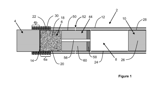
Figure 1 shows a cross-sectional view of an aerosol generating article in
accordance with
the present invention;
Figure 2 shows a test apparatus for determining the effect of different second
heat-
conducting elements on thermal loss from an aerosol generating article;
Figure 3 shows a graph of outer surface temperature against time for different
second
heat-conducting element materials when tested on the apparatus of Figure 2;
Figure 4 shows a graph of internal temperature against time for different
second heat-
conducting element materials when tested on the apparatus of Figure 2;
CA 03006006 2018-05-23
WO 2017/114744
PCT/EP2016/082351
- 23 -
Figure 5 shows a graph of internal temperature against time for second heat-
conducting
elements when tested on the apparatus of Figure 2 to show the effect of
different embossing
patterns;
Figure 6 shows a graph of internal temperature against time for second heat-
conducting
elements when tested on the apparatus of Figure 2 to show the effect of
different surface
coatings;
Figure 7 shows a summary of the measured emissivity values for the different
embossing
patterns and the different surface coatings used in the tests of Figures 5 and
6;
Figures 8 and 9 show test data for aerosol generating articles comprising
second heat-
conducting elements having the different surface coatings of Figure 6 and
smoked according to
the Health Canada Intense smoking regime; and
Figures 10 and 11 show comparative test data for aerosol generating articles
comprising
second heat-conducting elements having a surface coating of calcium carbonate
and smoked
according to the Health Canada Intense smoking regime.
The aerosol generating article 2 shown in Figure 1 comprises a combustible
carbonaceous heat source 4, an aerosol-forming substrate 6, an airflow
directing element 44,
an elongate expansion chamber 8 and a mouthpiece 10 in abutting coaxial
alignment. The
combustible carbonaceous heat source 4, aerosol-forming substrate 6, airflow
directing element
44, elongate expansion chamber 8 and mouthpiece 10 are overwrapped in an outer
wrapper of
cigarette paper 12 of low air permeability.
As shown in Figure 1, a non-combustible, gas-resistant, first barrier coating
14 is provided
on substantially the entire rear face of the combustible carbonaceous heat
source 4. In an
alternative embodiment, a non-combustible, substantially air impermeable first
barrier is
provided in the form of a disc that abuts the rear face of the combustible
carbonaceous heat
source 4 and the front face of the aerosol-forming substrate 6.
The combustible carbonaceous heat source 4 is a blind heat source so that air
drawn
through the aerosol generating article for inhalation by a user does not pass
through any airflow
channels along the combustible heat source 4.
The aerosol-forming substrate 6 is located immediately downstream of the
combustible
carbonaceous heat source 4 and comprises a cylindrical plug of tobacco
material 18 comprising
glycerine as an aerosol former and circumscribed by a filter plug wrap 20.
A heat-conducting component comprises a first heat-conducting element 22
consisting of
a tube of aluminium foil surrounds and is in contact with a downstream portion
4b of the
combustible carbonaceous heat source 4 and an abutting upstream portion 6a of
the aerosol-
forming substrate 6. As shown in Figure 1, a downstream portion of the aerosol-
forming
substrate 6 is not surrounded by the first heat-conducting element 22.
CA 03006006 2018-05-23
WO 2017/114744
PCT/EP2016/082351
- 24 -
An airflow directing element 44 is located downstream of the aerosol-forming
substrate 6
and comprises an open-ended, substantially air impermeable hollow tube 56 made
of, for
example, cardboard, which is of reduced diameter compared to the aerosol-
forming substrate 6.
The upstream end of the open-ended hollow tube 56 abuts the aerosol-forming
substrate 6.
The downstream end of the open-ended hollow tube 56 is surrounded by an
annular
substantially air impermeable seal 58 of substantially the same diameter as
the aerosol-forming
substrate 6. The remainder of the open-ended hollow tube is embedded in a
cylindrical plug of
cellulose acetate tow 60 of substantially the same diameter as the aerosol-
forming substrate 6.
The open-ended hollow tube 56 and cylindrical plug of cellulose acetate tow 60
are
circumscribed by an air permeable inner wrapper 50. A circumferential row of
air inlets 52 are
provided in the outer wrapper 12 and the inner wrapper 50.
The elongate expansion chamber 8 is located downstream of the airflow
directing element
44 and comprises a cylindrical open-ended tube of cardboard 24. The mouthpiece
10 of the
aerosol generating article 2 is located downstream of the expansion chamber 8
and comprises
a cylindrical plug of cellulose acetate tow 26 of very low filtration
efficiency circumscribed by
filter plug wrap 28. The mouthpiece 10 may be circumscribed by tipping paper
(not shown).
The heat-conducting component further comprises a second heat-conducting
element 30
consisting of a tube of aluminium foil surrounds and is in contact with the
outer wrapper 12. The
second heat-conducting element 30 is positioned over the first heat-conducting
element 22 and
is of the same dimensions as the first heat-conducting element 22. The second
heat-
conducting element 30 therefore directly overlies the first heat-conducting
element 22, with the
outer wrapper 12 between them. The outer surface of the second heat-conducting
element 30
is coated with a surface coating, such as a glossy coloured coating, which
yields an emissivity
value of less than about 0.6, preferably less than about 0.2, for the outer
surface of the second
heat-conducting element 22.
In use, the user ignites the combustible carbonaceous heat source 4, which
heats the
aerosol-forming substrate 6 by conduction. The user then draws on the
mouthpiece 10 so that
cool air is drawn into the aerosol generating article 2 through the air inlets
52. The drawn air
passes upstream between the exterior of the open-ended hollow tube 56 and the
inner wrapper
50 through the cylindrical plug of cellulose acetate tow 60 to the aerosol-
forming substrate 6.
The heating of the aerosol-forming substrate 6 releases volatile and semi-
volatile compounds
and glycerine from the tobacco material 18, which are entrained in the drawn
air as it reaches
the aerosol-forming substrate 6. The drawn air is also heated as it passes
through the heated
aerosol-forming substrate 6. The heated drawn air and entrained compounds then
pass
downstream through the interior of the hollow tube 56 of the airflow directing
element 44 to the
expansion chamber 8, where they cool and condense. The cooled aerosol then
passes
CA 03006006 2018-05-23
WO 2017/114744
PCT/EP2016/082351
- 25 -
downstream through the mouthpiece 10 of the aerosol generating article 2 into
the mouth of the
user.
The non-combustible, substantially air impermeable, barrier coating 14
provided on the
entire rear face of the combustible carbonaceous heat source 4 isolates the
combustible
carbonaceous heat source 4 from the airflow pathways through the aerosol
generating article 2
such that, in use, air drawn through the aerosol generating article 2 along
the airflow pathways
does not directly contact the combustible carbonaceous heat source 4.
The second heat-conducting element 30 retains heat within the aerosol
generating article
2 to help maintain the temperature of the first heat-conducting element 22
during smoking. This
in turn helps maintain the temperature of the aerosol-forming substrate 6 to
facilitate continued
and enhanced aerosol delivery.
Figure 2 shows a test apparatus 100 for simulating the heating of an aerosol
generating
article in accordance with the present invention, which is used for testing
the performance of
different second heat-conducting elements, including those having different
surface treatments.
The test apparatus 100 comprises a cylindrical aluminium body 102 around which
a test
material 104 is wrapped. The test material 104 simulates a second heat-
conducting element in
an aerosol generating article according to the invention.
During the test, a coil heater 106 embedded within the aluminium body 102
simulates the
heating effect of a combustible heat source at the upstream end of an aerosol
generating
article. To enable measurement of the emissivity of the outer surface of the
test material 104 in
accordance with ISO 18434-1, the voltage across the coil heater 106 is
increased in stages to
provide periods of stabilised elevated temperature during the heating process.
Specifically, the
voltage across the coil heater 106 is increased incrementally to 6 volts, 11
volts, 14 volts, 17
volts, 19.5 volts, 21 volts, and 24 volts, with a delay of 10 minutes between
each voltage
increase to allow the temperature of the test material 104 to stabilise.
During the test procedure, first and second thermocouples 108 and 110 record
the
temperature at the outer surface of the test material 104 and the interior of
the aluminium body
102 respectively. Each thermocouple 108, 110 is positioned 7 millimetres from
the upstream
end 112 of the aluminium body 102.
Figure 3 shows a graph of surface temperature, measured using thermocouple
108,
against time for different second heat-conducting element materials when
tested on the
apparatus of Figure 2. The materials tested for the second heat-conducting
element were:
aluminium only; paper only; a paper-aluminium co-laminate with the aluminium
layer forming the
outer surface; and a paper-aluminium co-laminate with the paper layer forming
the outer
surface. The aluminium had a measured emissivity of 0.09 and the paper had a
measured
emissivity of 0.95. It is shown in Figure 3 that the lower emissivity of the
aluminium layer
CA 03006006 2018-05-23
WO 2017/114744
PCT/EP2016/082351
- 26 -
compared to the paper layer resulted in a higher outer surface temperature of
the second heat-
conducting element due to reduced radiative heat loss.
As shown in Figure 4, which shows a graph of interior temperature against
time,
measured using thermocouple 110 during the same test as Figure 3, the reduced
radiative heat
loss achieved by using a second heat-conducting element having a low
emissivity at the outer
surface also results in an increased internal temperature within the simulated
aerosol
generating article. Based on this data, the present inventors have recognised
that utilising a
second heat-conducting element having a low emissivity at its outer surface
provides a more
thermally efficient aerosol generating article and therefore a desirable
increase in the internal
temperature during smoking.
The heating test was repeated using three different paper-aluminium co-
laminates each
having a different embossment pattern, and in each case with the aluminium
layer forming the
outer surface of the second heat-conducting element. The test data is shown in
Figure 5, which
shows the internal temperature measured with thermocouple 110 against time for
all three test
materials, as well as the data for the non-embossed co-laminate (for both
aluminium and paper
forming the outer surface) for reference. It is shown in the data in Figure 5
that embossing the
material forming the second heat conducting element has substantially no
effect on the internal
temperature of the simulated aerosol generating article during the heating
test, which can be
attributed to the embossing having substantially no effect on the emissivity
at the outer surface
of the second heat-conducting element. This is shown in the data in Figure 7,
which shows that
the measured values of emissivity for the three embossing patterns were 0.092,
0.085 and
0.092, which are substantially the same as the emissivity value of 0.09 for
the non-embossed
co-laminate with the aluminium layer forming the outer surface.
The heating test was repeated again using six different paper-aluminium co-
laminates
each having a different surface coating of coloured ink applied over the outer
surface of the
aluminium layer, and in each case with the aluminium layer forming the outer
surface of the
second heat-conducting element. The six different surface coatings tested
were: glossy gold
colour; matt pink colour; glossy pink colour; matt green colour; glossy orange
colour; and matt
black colour. The test data is shown in Figure 6, which shows the internal
temperature
measured with thermocouple 110 against time for all six test materials, as
well as the data for
the non-coated co-laminate (for both aluminium and paper forming the outer
surface) for
reference. It is shown in Figure 6 that coating the aluminium layer in a matt
black ink resulted in
an internal temperature during the test that was similar to that obtained with
the paper layer of
the co-laminate forming the outer surface of the second heat-conducting
element. The other
inks had no significant effect on the internal temperature of the simulated
aerosol generating
article when compared with the data for the uncoated aluminium layer forming
the outer surface
of the second heat-conducting element. Therefore, based on this data, the
present inventors
CA 03006006 2018-05-23
WO 2017/114744
PCT/EP2016/082351
- 27 -
have recognised that applying a surface coating to the material forming the
outer surface of the
second heat-conducting element may have a significant effect on the thermal
performance of
the second heat-conducting element, depending on the particular surface
coating used.
In this regard, the emissivity of the different test materials used for the
test in Figure 6 was
measured and the data is presented in Figure 7. It is shown in Figure 7 that,
although applying
a coloured coating to the aluminium layer increases the emissivity compared to
the uncoated
aluminium layer, the effect was most significant when the coating was a matt
black colour.
Accordingly, there is a direct correlation between the increase in the
emissivity value as a result
of applying a coloured coating and the resulting decrease in internal
temperature of the
simulated aerosol generating article during the heating test. Accordingly, the
present inventors
have recognised that, when applying a surface coating to the outer surface of
the second heat-
conducting element, the surface coating should be selected to maintain or
provide a low
emissivity value to prevent an undesirable reduction, or yield a desirable
increase, in the
internal temperature of the aerosol generating article during smoking.
Aerosol generating articles were constructed using the six coated co-laminates
used for
the tests in Figures 6 and 7, with the coated aluminium layer forming the
outer surface of the
second heat-conducting element in each case. For reference, an aerosol
generating article was
also constructed using a paper-aluminium co-laminate with an uncoated matt
aluminium layer
forming the outer surface of the second heat conducting element. In each case
the co-laminate
comprised a paper layer having a thickness of 73 micrometres and a basis
weight of 45 grams
per square metre laminated to an aluminium foil having a thickness of 6.3
micrometres. The
aerosol generating articles were then smoked according to the Health Canada
Intense smoking
regime (55 cubic centimetres puff volume, 30 second puff frequency, 2 second
puff duration)
and the resulting data for delivery of glycerine, nicotine and total
particulate matter (TPM) is
shown in Figures 8 and 9.
Figures 8 and 9 show that the matt pink, matt green, glossy pink and glossy
orange
coatings resulted in similar glycerine, nicotine and TPM delivery compared to
the reference
uncoated matt aluminium article. The glossy gold coating resulted in reduced
but acceptable
delivery compared to the reference article. The matt black coating resulted in
a significantly
reduced and unacceptable delivery compared to the reference article. Based on
the data in
Figures 8 and 9 combined with the measured emissivity values in Figure 7, the
present
inventors have recognised that when providing a surface treatment on the outer
surface of a
material forming a second heat-conducting element the surface treatment should
be selected to
maintain or provide an emissivity of less than about 0.6.
In a further example, aerosol-generating articles were constructed to examine
the effect of
a calcium carbonate coating on an outer surface of a second heat-conducting
element. Sets of
first and second reference articles were constructed, each having an uncoated
second heat-
CA 03006006 2018-05-23
WO 2017/114744
PCT/EP2016/082351
- 28 -
conducting element, and then smoked according to the Health Canada Intense
smoking regime
(55 cubic centimetres puff volume, 30 second puff frequency, 2 second puff
duration). The
temperature profiles during smoking for the first and second reference
articles are shown in
Figures 10 and 11 (Figure 10 shows temperature measured at the downstream end
of the heat
source, and Figure 11 shows temperature measured at the upstream end of the
aerosol-forming
substrate). The second reference articles each include a heat source that
provides a greater
thermal output than the heat source of each of the first reference articles.
As a result, the
second reference articles exhibit a generally hotter temperature profile than
the first reference
articles.
For comparison, a set of third articles was constructed, each identical to the
second
reference articles except for the addition of a lacquer coating to the outer
surface of the second
heat-conducting elements, the lacquer comprising 60 percent calcium carbonate.
The set of
third articles was then smoked according to the same smoking regime and the
results are
shown in Figures 10 and 11. As shown in Figures 10 and 11, applying a calcium
carbonate
coating to the outer surface of the second heat-conducting elements of second
reference
articles modifies the temperature profiles of the second reference articles
during smoking so
that they approximate the temperature profiles of the first reference articles
during smoking,
despite the greater thermal output of the heat source in each second reference
article compared
to the thermal output of the heat source in each first reference article.
The embodiments and examples shown in Figures 1 to 11 and described herein
illustrate
but do not limit the invention. Other embodiments of the invention may be made
without
departing from the scope thereof, and it is to be understood that the specific
embodiments
described herein are not limiting.