Note: Descriptions are shown in the official language in which they were submitted.
CA 03006202 2018-05-23
WO 2017/096325
PCT/US2016/064856
AN IMPLANTABLE RENAL REPLACEMENT THERAPY SYSTEM
CROSS REFERENCE TO RELATED APPLICATIONS
[0001] This application claims priority to U.S. Patent Provisional
Application No.
62/262,915, filed December 4,2015, titled "AN IMPLANTABLE RENAL REPLACEMENT
THERAPY," which is herein incorporated by reference in its entirety.
INCORPORATION BY REFERENCE
[0002] All publications and patent applications mentioned in this
specification are herein
incorporated by reference to the same extent as if each individual publication
or patent
application was specifically and individually indicated to be incorporated by
reference.
FIELD
[0003] The present invention is in the technical field of medical devices
and renal
replacement therapies.
BACKGROUND
[0004] There are nearly three million patients with kidney failure (end-
stage renal disease)
around the world. Patients' survival depend on dialysis, a thrice a week renal
replacement
therapy that they undergo until they receive a kidney transplant. The
mortality rate of patients
under dialysis is more than 60% in five years. On average, a year of dialysis
of each patient costs
upwards of $82,000 in the United States. Patients have to use dialysis for
five to seven years on
average before they find a kidney donated for transplantation. Thrice a week
dialysis imposes
lifestyle restrictions on patients and they endure a lot more hardships from
complications due to
dialysis treatment.
[0005] An implantable renal replacement therapy can provide access to
treatment
continuously and automatically 24/7 and removes the hardship of going to the
dialysis clinics. In
general, it can provide a more normal life for kidney patients and it can be a
temporary solution
for the patients in need of a kidney transplant until they find a kidney
donated for transplantation.
[0006] Kidneys receive 25% of cardiac output. The total blood volume passes
through
kidneys every 4-5 minutes. Kidneys produce 180 liters of fluid per day and
reabsorbs 178.5
liters of it, generating 1.5 liter of acidic (pH-6) urine per day which also
contains uremic toxins.
- 1 -
CA 03006202 2018-05-23
WO 2017/096325
PCT/US2016/064856
SUMMARY OF THE DISCLOSURE
[0007] This invention describes a medical device which is an implantable
renal replacement
therapy for patients with end stage renal disease.
[0008] Blood is diverted from iliac artery (or another artery) into a
filtration system which
removes uremic toxins and excess water from blood. Blood is passed back into
iliac vein (or
another vein) and the uremic toxins and excess water go to the bladder.
[0009] The device has (i) a filtration system which blocks passage of
blood proteins such as
albumin but removes uremic toxins and excess water and (ii) a re-absorption
system to re-claim
some salt and water back into the blood from the filtrate of the filtration
system. The device is
connected to a control unit outside the body of the patient through a
percutaneous driveline. The
percutaneous driveline has (i) wires to electronics inside the body of the
patient and (ii) at least
one tube to transfer washing fluid to clean the filters and open the pores in
case of clogging.
Patient also carries batteries to power the device.
[0010] In general, in one embodiment, a renal replacement therapy system,
including (1) a
filtration system having a feed side, a filtrate side and a non-silicon
ceramic filter separating the
feed side and the filtrate side; (2) a re-absorption system having a feed
side, a filtrate side and a
non-silicon ceramic filter separating the feed side and the filtrate side; (3)
a valveless blood flow
circuit in communication with an arterial graft, an inlet to the filtration
system feed side, an
outlet to the filtration system feed side, an inlet to the re-absorption
system filtrate side, an outlet
to the re-absorption system filtrate side and a venous graft; (4) a
percutaneous drive line
including a fluid supply channel, a fluid return channel, a power cable, and a
data
communications cable; (5) a filtration system inlet valve in communication
with the fluid supply
channel and an inlet to the filtration system filtrate side; (6) a re-
absorption system first outlet
valve in communication with the re-absorption system feed side and the fluid
return channel; (7)
a re-absorption system second outlet valve in communication with the re-
absorption system feed
side and a graft in communication with a bladder or a urine collection bag ;
(8) a filtrate pump
with an inlet in communication with the filtration system filtrate side and an
outlet in
communication with the re-absorption system feed side; and (9) an implantable
housing
containing the filtration system, the re-absorption system, and the filtrate
pump.
[0011] The implantable housing can be completely sealed except for four
openings.
[0012] The four openings can be positioned to provide communication to an
interior portion
of the implantable housing for the percutaneous drive line, the blood flow
circuit inlet to the
filtration system feed side; the blood flow circuit outlet to the re-
absorption system filtrate side
and an opening in communication with the re-absorption system second outlet
valve.
[0013] The implantable housing can be completely sealed except for five
openings.
- 2 -
CA 03006202 2018-05-23
WO 2017/096325
PCT/US2016/064856
[0014] The five openings can be positioned to provide communication to an
interior portion
of the implantable housing for a fluid supply line, a fluid return line, the
blood flow circuit inlet
to the filtration system feed side; the blood flow circuit outlet to the re-
absorption system filtrate
side and an opening in communication with the re-absorption system second
outlet valve.
[0015] The filtration system non-silicon ceramic filter can be selected to
filter blood
components less than 66,500 Daltons into the filtration system filtrate side.
[0016] The re-absorption system non-silicon ceramic filter can be sized
to pass components
within the filtrate feed side having a molecular weight of less than 500
Daltons into the re-
absorption system filtrate side and into the valveless blood flow circuit.
[0017] The filtration system non-silicon ceramic filter can be selected to
maintain
substantially all albumin within the blood flowing within the valveless blood
flow circuit flowing
from the inlet to the filtration system feed side through the outlet to the
filtration system feed
side while passing through to the filtration system filtrate side molecular
weight fluids having a
molecular weight below 65,000 Dalton.
[0018] The filtration system non-silicon ceramic filter can contain one or
more of aluminum
oxide, zinc oxide, titanium oxide, and pyrolytic carbon.
[0019] The filtration system filter can contain one or more of the
materials and structures
with fracture toughness KIC values of higher than 1.00 (MPa . m1/2)
[0020] The re-absorption system non-silicon ceramic filter can contain
one or more of
aluminum oxide, zinc oxide, titanium oxide, and pyrolytic carbon.
[0021] The filtration system can include the fluid supply channel, the
fluid return channel,
the power cable, and the data communications cable of the percutaneous drive
line are enclosed
within a single biocompatible sheath.
[0022] The filtration system can include one or more of a sensor to
measure a pressure
within the filtration system; a sensor to measure a flow within the filtration
system; a sensor to
measure a pressure within the re-absorption system; or a sensor to measure a
flow within the re-
absorption system.
[0023] The filtration system can include one or more of a sensor to
measure a quantity of a
blood protein, a sensor to measure a quantity of a blood glucose, a sensor to
measure a quantity
of a blood urea or a sensor to measure a quantity of a blood creatinine within
the filtration
system.
[0024] The filtration system can include one or more of a sensor to
measure a quantity of a
blood protein, a sensor to measure a quantity of a blood glucose, a sensor to
measure a quantity
of a blood urea or a sensor to measure a quantity of a blood creatinine within
the re-absorption
system.
- 3 -
CA 03006202 2018-05-23
WO 2017/096325
PCT/US2016/064856
[0025] The system can include a sensor to indicate fouling or fracture
of the non-silicon
ceramic filter in the filtration system or a sensor to indicate fouling or
fracture of the non-silicon
ceramic filter in the re-absorption system.
[0026] In general, in one embodiment, the system can further include a
control unit with an
electronic display and a computer controller in electronic communication with
the filtration
system inlet valve, the re-absorption system first outlet valve, the re-
absorption system second
outlet valve and the filtrate pump.
[0027] The computer controller can be in electronic communication with
one or more of the
sensors.
[0028] The system can further include a blood pump with an inlet in
communication with the
arterial graft and an outlet in communication with the inlet to the filtration
system feed side.
[0029] The system can include the computer controller which can further
include a computer
readable instruction for operating the system in a preselected functioning
mode selected from a
filtration mode, a re-absorption mode, a filter cleaning mode and a urine
flushing mode.
[0030] The pre-selected functioning mode can be the filtration mode with
the computer
readable instruction for operating the system which can further include
instructions to close the
filtration system inlet valve, the re-absorption system first outlet valve,
the re-absorption system
second outlet valve while controlling the operation of the filtrate pump to
pump filtrate from the
filtration system to the re-absorption system.
[0031] The pre-selected functioning mode can be the re-absorption mode with
the computer
readable instruction for operating the system which can further include
instructions to close the
filtration system inlet valve, the re-absorption system first outlet valve,
the re-absorption system
second outlet valve while controlling the operation of the filtrate pump to
pump filtrate through
the re-absorption system non-silicon ceramic filter.
[0032] The pre-selected functioning mode can be the filter cleaning mode
with the computer
readable instruction for operating the system which can further include
instructions to open the
filtration system inlet valve, open the re-absorption system first outlet
valve, close the re-
absorption system second outlet valve while controlling the operation of the
filtrate pump to
pump a cleaning fluid.
[0033] The pre-selected functioning mode can be the urine flushing mode
with the computer
readable instruction for operating the system which can further include
instructions to close the
filtration system inlet valve, close the re-absorption system first outlet
valve, open the re-
absorption system second outlet valve while controlling the operation of the
filtrate pump to
pump filtrate from the re-absorption system to the and the graft in
communication with the
bladder or a urine collection bag.
- 4 -
CA 03006202 2018-05-23
WO 2017/096325
PCT/US2016/064856
[0034] The pre-selected functioning mode can be the service mode with
the computer
readable instruction for operating the system and van further include
instructions to open or close
the filtration system inlet valve, open or close the re-absorption system
first outlet valve, open or
close the re-absorption system second outlet valve while controlling the
operation of the filtrate
pump to pump or not to pump the filtrate from the re-absorption system to the
and the graft in
communication with the bladder.
[0035] The system can include the computer readable instruction for
operating the system
which can further include controlling operation of the blood pump during a pre-
selected
functioning mode.
[0036] The system can further include at least one battery pack connected
to the control unit.
[0037] The controller display can further include a touch screen
selecting one of the pre-
selected functioning modes.
[0038] In general, in one embodiment, a method of performing a renal
replacement filtration
therapy includes (1) flowing blood from a patient arterial graft into a
valveless blood flow circuit
that flows through an inlet to a filtration system feed side, an outlet to a
filtration system feed
side, an inlet to a re-absorption system filtrate side, an outlet to a re-
absorption system filtrate
side and a venous graft; (2) filtering a portion of the components in the
flowing blood in the
filtration system feed side through a first non-silicon ceramic filter to
provide a filtrate into a
filtration system filtrate side; (3) pumping a portion of the filtrate from
the filtration system
filtrate side to a feed side of a re-absorption system; and (4) filtering a
portion of the filtrate in
the feed side of the re-absorption system through a second non-silicon ceramic
filter to provide a
portion of the filtrate components into the re-absorption system filtrate side
in communication
with the blood flow circuit.
[0039] The method can further include (1) performing one or more of the
flowing, filtering,
pumping and filtering steps by operating a filtration system inlet valve in
communication with a
fluid supply channel of a percutaneous drive line and an inlet to the
filtration system filtrate side,
(2) a re-absorption system first outlet valve in communication with the re-
absorption system feed
side and a fluid return channel of the percutaneous drive line, (3) a re-
absorption system second
outlet valve in communication with the re-absorption system feed side and a
graft in
communication with a bladder, and (4) a filtrate pump with an inlet in
communication with the
filtration system filtrate side and an outlet in communication with the re-
absorption system feed
side using a computer controller in electronic communication with the
filtration system inlet
valve, the re-absorption system first outlet valve, the re-absorption system
second outlet valve
and the filtrate pump.
- 5 -
CA 03006202 2018-05-23
WO 2017/096325
PCT/US2016/064856
[0040] The computer controller can be in wireless electronic
communication with the
filtration system inlet valve, the re-absorption system first outlet valve,
the re-absorption system
second outlet valve and the filtrate pump.
[0041] The computer controller can be in electronic communication with
the filtration
system inlet valve, the re-absorption system first outlet valve, the re-
absorption system second
outlet valve and the filtrate pump using a wired connection within the
percutaneous drive line.
[0042] The method can further include executing a computer readable
instruction in the
computer controller for operating the therapy system in a preselected
functioning mode selected
from a filtration mode, a re-absorption mode, a filter cleaning mode and a
urine flushing mode.
[0043] The pre-selected functioning mode can be the filtration mode and
executing the
computer readable instruction for operating the system for closing the
filtration system inlet
valve, the re-absorption system first outlet valve, the re-absorption system
second outlet valve
while controlling the operation of the filtrate pump for pumping filtrate from
the filtration system
to the re-absorption system.
[0044] The pre-selected functioning mode can be the re-absorption mode and
executing the
computer readable instruction for operating the system for closing the
filtration system inlet
valve, the re-absorption system first outlet valve, the re-absorption system
second outlet valve
while controlling the operation of the filtrate pump for pumping filtrate
through the second non-
silicon ceramic filter.
[0045] The pre-selected functioning mode can be the filter cleaning mode
and executing the
computer readable instruction for operating the system for opening the
filtration system inlet
valve and the re-absorption system first outlet valve and closing the re-
absorption system second
outlet valve while controlling the operation of the filtrate pump for pumping
a cleaning fluid.
[0046] The pre-selected functioning mode can be the urine flushing mode
and executing the
computer readable instruction for operating the system for closing the
filtration system inlet
valve and the re-absorption system first outlet valve and opening the re-
absorption system
second outlet valve while controlling the operation of the filtrate pump for
pumping filtrate from
the re-absorption system to the and the graft in communication with the
bladder.
[0047] The method can include the flowing blood from a patient step
which can further
include executing a computer readable instruction for controlling operation of
a blood pump
during a pre-selected functioning mode.
[0048] The filtering step using the first non-silicon ceramic filter can
provide a filtrate of
blood components less than 66,500 Daltons into the filtration system filtrate
side.
- 6 -
CA 03006202 2018-05-23
WO 2017/096325
PCT/US2016/064856
[0049] The filtering step using the second non-silicon ceramic filter
can provide a filtrate
with components within the filtrate feed side having a molecular weight of
less than 500 Daltons
into the re-absorption system filtrate side and into the valveless blood flow
circuit.
[0050] The first non-silicon ceramic filter can be selected to maintain
substantially all
albumin within the blood flowing within the valveless blood flow circuit
flowing from the inlet
to the filtration system feed side through the outlet to the filtration system
feed side while
passing through to the filtration system filtrate side molecular weight fluids
having a molecular
weight below 65,000 Dalton.
[0051] The filtering steps through the first non-silicon ceramic filter
and the second non-
silicon ceramic filter can include filtering pathways formed in one or more of
aluminum oxide,
zinc oxide, titanium oxide, and pyrolytic carbon.
[0052] The method can further include (1) one or more of communicating a
pressure reading
from a sensor measuring a pressure within the filtration system to the
controller using the data
communication channel of the percutaneous drive line; (2) communicating a
pressure reading
from a sensor measuring a flow within the filtration system to the controller
using the data
communication channel of the percutaneous drive line; (3) communicating a
pressure reading
from a sensor measuring a pressure within the re-absorption system to the
controller using the
data communication channel of the percutaneous drive line; (4) or
communicating a pressure
reading from a sensor measuring a flow within the re-absorption system to the
controller using
the data communication channel of the percutaneous drive line.
[0053] The method can further include communicating an output of one or
more of a sensor
to measure a quantity of a blood protein, a sensor to measure a quantity of a
blood glucose, a
sensor to measure a quantity of a blood urea or a sensor to measure a quantity
of a blood
creatinine within the filtration system to the controller using the data
communication channel of
the percutaneous drive line.
[0054] The method can further include communicating an output of one or
more of a sensor
to indicate fouling or fracture of the non-silicon ceramic filter in the
filtration system or a sensor
to indicate fouling or fracture of the non-silicon ceramic filter in the re-
absorption system to the
controller using the data communication channel of the percutaneous drive
line.
[0055] The method can further include executing computer readable
instructions in the
computer controller for operating the filtration system inlet valve, the re-
absorption system first
outlet valve, the re-absorption system second outlet valve and the filtrate
pump in response to
one or more communicating steps.
- 7 -
CA 03006202 2018-05-23
WO 2017/096325
PCT/US2016/064856
[0056] The implantable housing containing the components of the
filtration system and the
re-absorption system can be percutaneously implanted adjacent to one of an
artery, a vein or a
bladder.
[0057] The implantable housing containing the components of the
filtration system and the
re-absorption system can be subcutaneously implanted to be adjacent to a skin
of the patient
receiving the therapy.
[0058] The controller and a housing containing the components of the
filtration system and
the re-absorption system can be external to the patient and connected
percutaneously to the artery
graft, the vein graft and the graft connected to the bladder.
[0059] Components of the filtration system and re-absorption system can be
subcutaneously-
implanted with appropriate percutaneous access or subcutaneous access to a
left side vein, a left
side artery and a bladder or a urine collection bag or to a right side vein, a
right side artery and a
bladder or a urine collection bag.
[0060] The filtration and re-absorption system or associated method can
provide processed
filtrate or double processed filtrate.
BRIEF DESCRIPTION OF THE DRAWINGS
[0061] The novel features of the invention are set forth with
particularity in the claims that
follow. A better understanding of the features and advantages of the present
invention will be
obtained by reference to the following detailed description that sets forth
illustrative
embodiments, in which the principles of the invention are utilized, and the
accompanying
drawings of which:
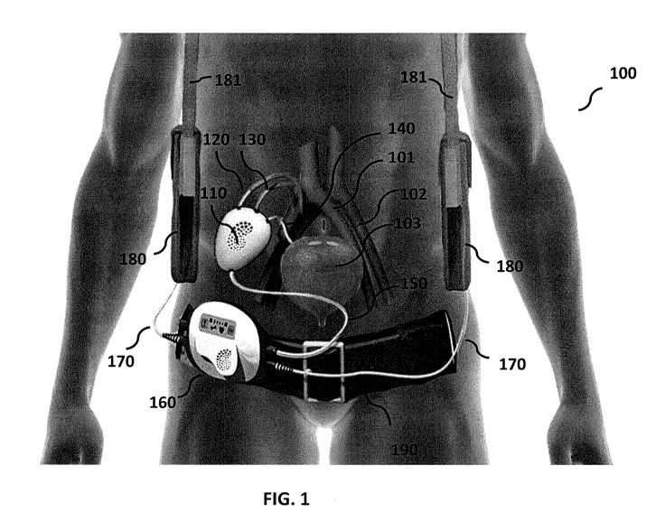
[0062] FIG. 1 shows the implantable renal replacement therapy device
100.
[0063] FIG. 2 is a schematic side view diagram 200 of the implanted
filtration system 110.
[0064] FIG. 3 is a schematic diagram 300 of the implanted filtration
system 110 with a blood
pump 255.
[0065] FIG. 4 is a view 400 of the implanted filtration system 110 as in
FIG. 2 configured to
operate in a urine flushing mode.
[0066] FIG. 5 is a view 425 of the implanted filtration system 110 as in
FIG. 2 configured to
operate in a filter cleaning mode.
[0067] FIG. 6 is a schematic view 450 of the implanted filtration system
110 as in FIG. 3
configured to operate in a urine flushing mode.
[0068] FIG. 7 is a schematic view 475 of the implanted filtration system
110 as in FIG. 3
configured to operate in a filter cleaning mode.
- 8 -
CA 03006202 2018-05-23
WO 2017/096325
PCT/US2016/064856
[0069] FIG. 8 is a view of a filtration system as in FIG. I implanted at
an appropriate left
side implantation site as described above.
[0070] FIG. 9 is a therapy method 500 which describes the blood cleaning
methods,
techniques and mechanisms which are used in the implantable renal replacement
therapy system
of FIGs. 1, 2 or 3 and other configurations such as external (extracorporeal)
and subcutaneously-
implanted versions of the embodiments of the device.
[0071] FIG. 10 is a therapy method 600 which describes a more general
form of method 500
of FIG. 9 for applications beyond renal replacement therapy.
DETAILED DESCRIPTION
[0072] The present invention relates to renal replacement therapies, and
particularly to an
implantable medical device to remove uremic toxins and excess water from blood
of patients
with end stage renal disease and to excrete some of them through bladder. This
invention also
describes how to re-absorb some molecules with molecular weight <500 Da such
as some salts
and water back into the blood from what was filtered from blood.
[0073] The various alternative embodiments of the implantable system for
renal replacement
therapy may include a wide variety of different configurations providing many
advantages over
conventional systems. In one of more different embodiments of the inventive
system may
include, in any combination one of more of the following advantageous
capabilities:
[0074] The use of non-silicon ceramic filter materials including a
filtration system having a
feed side, a filtrate side and a non-silicon ceramic filter separating the
feed side and the filtrate
side along with or optionally a re-absorption system having a feed side, a
filtrate side and a non-
silicon ceramic filter separating the feed side and the filter side. The
filtration system non-silicon
ceramic filter and the re-absorption system non-silicon ceramic filter may
contain filtration flow
paths formed from one or more of aluminum oxide, zinc oxide, titanium oxide,
and pyrolytic
carbon in any configuration.
[0075] At least one filter to block passage of albumin (MW-66.5 kDa )
from blood under
defined pressure, while letting blood components and fluids with molecular
weights smaller than
66.5 kDa pass though;
[0076] At least one filter to re-absorb some molecules with molecular
weight MW < 500 Da
back into the blood from the filtrate of the filter(s) described in (a), while
blocking the passage of
some other molecules with molecular weight MW < 500 Da;
[0077] At least one pump to create and maintain defined pressure on at
least one of the
filters.
- 9 -
CA 03006202 2018-05-23
WO 2017/096325
PCT/US2016/064856
[0078] At least one cleaning mechanism to open pores and clean the
surface of filters in case
of fouling;
[0079] At least one optional sensor measuring quantities such as
pressure, membrane
fouling, membrane fracture, blood protein, blood glucose, blood urea, blood
creatinine, the
sensor may be placed directly in contact with body fluids or positioned for
measuring the values
indirectly without contact with the body fluids;
[0080] At least a power source which is a battery or a wired connection
or a wireless method
of transferring electric power to the device or combination of at least two of
these methods;
[0081] At least one control unit;
[0082] A wired or wireless communication system to establish a line of
communication
between the device inside the body of the patient and a control unit outside
the body of the
patient, to send and receive data and to control the function of different
components of the
device. These features and others are better appreciated with reference to
FIGs. 1-10 and the
description that follows.
[0083] In some embodiments, a protein-free or substantially free
ultrafiltrate generated by
embodiments of the present invention may be in itself valuable and useful for
ends other than the
removal of toxins in blood filtering applications. For example, in various
embodiments of the
ultrafiltration devices of the present invention also find use in diagnostic
applications. For
example, the devices provides a means for selectively screening out undesired
molecules (e.g.,
proteins) within fluids, such that a particular analyte to be analyzed (e.g.,
small molecules such
as glucose, lactic acid, electrolytes, ions, including, but not limited to,
potassium, sodium,
calcium, chloride, oxygen, and carbon dioxide) in the absence of interfering
molecules. Present
electrochemical sensors for glucose measurement are severely hampered by
protein fouling of
the sensor, and great effort is devoted to the invention of fouling retardants
to prolong sensor life.
An ultrafiltrate substantially free of proteins, but still containing smaller
constituents of blood,
including but not limited to sodium, potassium, chloride, glucose, provides a
solution to assay for
glucose concentration without protein fouling. Thus, various embodiments of
the present
invention further provide systems for use in the analysis of small molecule,
including, but not
limited to those listed above. Furthermore, as the intracellular aqueous
milieu differs from
extracellular fluid, the separate testing of whole blood and a protein and
cell-free ultrafiltrate for
electrolyte compositions, magnetic susceptance, optical, infrared, or magnetic
resonance
spectroscopy, and other physical properties of matter, provides detailed
information regarding
the cellular composition of the blood.
[0084] Furthermore, in still another aspect a protein and cell free
ultrafiltrate of blood so
generated may be in itself valuable and useful for ends other than the removal
of toxins and the
- 10 -
CA 03006202 2018-05-23
WO 2017/096325
PCT/US2016/064856
measurement of the constituents of blood. The constituents of blood necessary
for at least
temporary support of a metabolically active cell are small in molecular size
(including but not
limited to oxygen, glucose, insulin, triiodothyronine, and retinoic acid, for
example) while those
immune mediators responsible for rejection of an allograft or xenograft are
large in molecular
size, such as antibodies, or components of the complement cascade, or reside
in cell membranes,
such as the major histocompatibility complexes. Thus a stream of ultrafiltrate
of blood may be
used to supply nutrients and carry away wastes by an efficient convective
transport process,
rather than by less efficient diffusive transport. As a result, various
embodiments of the systems
described herein may be directly applicable to any generalized cell population
considered for
transplantation, including but not limited to islet cell transplantation,
liver cell transplantation,
kidney cell transplantation, and in general transplant of any allo- or xeno-
geneic cell type.
[0085] As used herein, the term "free of" refers to fluids of mixtures
that have had one or
more components (e.g., protein components) removed. "Substantially free of'
fluids or mixtures
are at least 50% free, preferably at least 75% free, and more preferably at
least 90% free from a
component with which they are otherwise naturally associated. For example, a
fluid that is
"substantially free of protein" is a fluid that has at least 50% or less of
the protein content of an
unfiltered or unpurified fluid.
[0086] As used herein, the term "dialysis" refers to a form of
filtration, or a process of
selective diffusion through a membrane; it is typically used to separate low-
molecular weight
solutes that diffuse through the membrane from the colloidal and high-
molecular weight solutes
which do not. In some embodiments, a feed of fluid is passed over a
semipermeable membrane,
and a feed of dialysate is passed over the other side of that membrane; the
membrane is wetted
by one or both solvents, and then there is diffusive transport of dissolved
solutes between the
fluids. The composition of one fluid, the dialysate, is used to deplete the
composition of the other
fluid, the feed fluid, of some molecule or molecules.
[0087] As used herein, the term "filtration" refers to a process of
separating particulate
matter from a fluid, such as air or a liquid, by passing the fluid carrier
through a medium that
will not pass the particulates.
[0088] As used herein, the term "ultrafiltration" refers to subjecting a
fluid to filtration,
where the filtered material is very small; typically, the fluid comprises
colloidal, dissolved
solutes or very fine solid materials, and the filter is a microporous,
nanoporous, or semi-
permeable medium. A typical medium is a membrane. The fluid to be filtered is
referred to as the
"feed fluid." During ultrafiltration, the feed fluid is separated into a
"permeate" or "filtrate" or
"ultrafiltrate," which has been filtered through the medium, and a
"retentate," which is that part
-11-
CA 03006202 2018-05-23
WO 2017/096325
PCT/US2016/064856
of the feed fluid which did not get filtered through the medium, or which is
retained by the
medium.
[00891 FIG. 1 shows the implantable renal replacement therapy device
100.
[0090] The implanted filtration system 110 is connected to the control
unit 160 through
percutaneous driveline 150.
[0091] The implanted filtration system 110 is connected to an artery
(such as iliac artery) 102
through the tube 120. The implanted filtration system 110 is connected to
iliac vein 101 (or any
other vein) through the tube 130.
[0092] The implanted filtration system 110 is connected to bladder 103
through the tube 140.
[0093] The tubes 120, 130 and 140 can be medical grade polymer grafts.
[0094] The implanted filtration system 110 has at least one filtration
system to remove some
blood components smaller than 65,000 Da in molecular weight (such as uremic
toxins, salts and
water) from blood.
[0095] The implanted filtration system 110 may have at least one re-
absorption system to
return some blood components with molecular weight smaller than 500 Daltons
(such as some
salt and water) back into the blood from the filtrate generated by the
filtration system.
[0096] The percutaneous driveline 150 contains power cords and fluid
transfer tubes and data
transfer lines and connects the control unit 160 to the implanted filtration
system 110. The
control unit 160 is connected to the batteries 180 through power cords 170.
The batteries can be
placed in hangers 181. Additionally, the control unit 160 is attached to the
belt 190.
[0097] The control unit 160 includes an electronic display (i.e., an LCD
or a touch screen)
and a computer controller in electronic communication with the components of
the filtration
system and the re-absorption system. The control unit 160 is configured to
operate or control,
for example, the filtration system inlet valve, the re-absorption system first
outlet valve, the re-
absorption system second outlet valve and the filtrate pump as in FIG. 2 as
well as a blood pump
when included as in FIG. 3. Tables 1 and 2 below provide exemplary
configurations of these
valves for operating the filtration and re-absorption system in a preselected
functioning mode.
By way of illustration and not limitation, the pre-selected functioning modes
may be selected
from a filtration mode, a re-absorption mode, a filter cleaning mode, a urine
flushing mode and a
service mode.
[0098] The fluid transfer tubes in the percutaneous driveline 150 are
mainly used to transfer
fluids into and out of the implanted filtration system 110 to wash the filters
and to open the
clogged pores of the filters. The washing solution can be at least one of
intravenous (IV) fluid,
saline solution, dialysate or replacement fluid used in renal replacement
therapy or any other
fluid that is safe to blood if it passes through the filters into the blood.
- 12-
CA 03006202 2018-05-23
WO 2017/096325
PCT/US2016/064856
[0099] At least one bag of washing solution can be attached to the
control unit 160. The
control unit 160 can pump the washing solution into the implanted filtration
system 110 through
the percutaneous driveline 150. The control unit 160 can collect the used
washing solution in the
same or another bag from the implanted filtration system 110 through the
percutaneous driveline
150.
[0100] The tubes 120, 130 and 140 are manufactured from bio-compatible
materials such as
medical grade Dacron or medical grade Polytetrafluoroethylene (PTFE).
[0101] FIG. 2 is a schematic side view diagram 200 of the implanted
filtration system 110.
[0102] Blood is diverted from an artery through the connection 120 into
the filtration system
210.
[0103] In one embodiment, the blood flow rate at the device inlet is up
to 200 ml/min which
is set by the size of the graft 120.
[0104] Blood is passed across the feed side 211 of at least one filter
230 in the filtration
system 210. The filtration system 210 has at least one filter to remove some
blood components
smaller than 65,000 Da in molecular weight (such as uremic toxins, salts and
water) from blood.
The filtrate is collected at the filtrate side 212 of the filter 230 and is
pumped into the feed side
222 of the re-absorption system 220 using a micro-pump 250 when the valves
260, 270 and 280
are closed. The micro-pump 250 creates a pressure on one side 222 of the
filter 240 which is
higher than the pressure at the other side 221 of the filter 240. Blood is
passed across one side
221 of at least one filter 240 in the re-absorption system 220. The re-
absorption system 220 has
at least one filter to return some blood components with molecular weight
smaller than 500
Daltons (mainly some salt and water) back into the blood from the filtrate
generated by the
filtration system 210.
[0105] In another embodiment, the re-absorption system 220 has at least
one filter to return
some blood components with molecular weight smaller than 66,500 Daltons back
into the blood
from the filtrate generated by the filtration system 210.
[0106] In another embodiment, the re-absorption system 220 has at least
one filter to return
some blood components with molecular weight smaller than 70,000 Daltons back
into the blood
from the filtrate generated by the filtration system 210.
[0107] In another embodiment, the re-absorption system 220 has at least one
filter to return
some blood components with molecular weight smaller than 200,000 Daltons back
into the blood
from the filtrate generated by the filtration system 210. In other
embodiments, the pore size or
filtration capacity of the filtration system and the pore size or filtration
capacity of the re-
absorption system many vary depending upon desired operating characteristics.
In some aspects,
one or more different or additional filters or other additional processing
components may be
- 13-
CA 03006202 2018-05-23
WO 2017/096325
PCT/US2016/064856
included within the implantable filtration unit 110, the control unit 160, an
embodiment of a
filtration system or an embodiment of a re-absorption system or as part of a
configuration within
one or both of the filtration system or the re-absorption system to provide
"processed filtrate" or
"double processed filtrate" capabilities as described herein.
[0108] In another embodiment, one of or the combination of filtrate side
212, feed side 222,
micro-pump 250 and re-absorption system 220 produce(s) at least one of
"processed filtrate" and
"double processed filtrate" as described below in method 500 (FIG. 9).
[0109] In another embodiment, one of or the combination of filtrate side
212, feed side 222,
micro-pump 250 and re-absorption system 220 produce(s) at least one of
"processed filtrate" and
"double processed filtrate" as described below in method 600 (FIG. 10).
[0110] Tube 215 connects filtration system 210 to the re-absorption
system 220.
[0111] Blood from the filtration system 210 goes into the re-absorption
system 220 through
the connection tube 215.
[0112] Tube 130 connects the re-absorption system 220 to the vein.
[0113] Blood from the re-absorption system 220 is passed into the vein 101
through the tube
130.
[0114] Blood flows from the tube 120 to the tube 130 due to the higher
blood pressure in the
artery 102 in comparison to the blood pressure in the vein 101.
[0115] FIG. 4 is a view 400 of the implanted filtration system 110 as in
FIG. 2 configured to
operate in a urine flushing mode.
[0116] When valve 260 and valve 270 are closed and valve 280 is open, the
micro-pump 250
can be used to transfer fluids from the 212 side of the filtration system 210
and the 222 side of
the re-absorption system 220 to bladder 103 through the tube 140.
[0117] FIG. 5 is a view 425 of the implanted filtration system 110 as in
FIG. 2 configured to
operate in a filter cleaning mode.
[0118] When valve 280 is closed and valve 260 and valve 270 are open, at
least one washing
solution can be pumped from percutaneous driveline into and out of the
implanted filtration
system 110 through the connection tubes 151 and 152. The washing solution can
minimize the
membrane fouling and pore clogging in the filters 230 and 240.
[0119] FIG. 3 is a schematic diagram 300 of the implanted filtration system
110 with a blood
pump 255.
[0120] Blood is diverted from an artery through the connection 120 and is
pumped into the
filtration system 210. In one embodiment, the blood flow rate at the device
inlet is up to 200
ml/min which is set by the blood pump 255. In another embodiment, blood flow >
500 ml /min,
preferably > 800 ml/min.
- 14-
CA 03006202 2018-05-23
WO 2017/096325
PCT/US2016/064856
[0121] Blood is passed across the feed side 211 of at least one filter
230 in the filtration
system 210. The filtration system 210 has at least one filter to remove some
blood components
smaller than 65,000 Da in molecular weight (such as uremic toxins, salts and
water) from blood.
The filtrate is collected at the filtrate side 212 of the filter 230 and is
pumped into the feed side
222 of the re-absorption system 220 using a micro-pump 250 when the valves
260, 270 and 280
are closed. The micro-pump 250 creates a pressure on one side 222 of the
filter 240 which is
higher than the pressure at the other side 221 of the filter 240. Blood is
passed across one side
221 of at least one filter 240 in the re-absorption system 220. The re-
absorption system 220 has
at least one filter to return some blood components with molecular weight
smaller than 500
Daltons (mainly some salt and water) back into the blood from the filtrate
generated by the
filtration system 210.
101221 In another embodiment, the re-absorption system 220 has at least
one filter to return
some blood components with molecular weight smaller than 66,500 Daltons back
into the blood
from the filtrate generated by the filtration system 210.
[01231
[0124] In another embodiment, the re-absorption system 220 has at least
one filter to return
some blood components with molecular weight smaller than 70,000 Daltons back
into the blood
from the filtrate generated by the filtration system 210.
[0125] In another embodiment, the re-absorption system 220 has at least
one filter to return
some blood components with molecular weight smaller than 200,000 Daltons back
into the blood
from the filtrate generated by the filtration system 210.
[0126] In another embodiment, one of or the combination of filtrate side
212, feed side 222,
micro-pump 250 and re-absorption system 220 produce(s) at least one of
"processed filtrate" and
"double processed filtrate" as described in schematic 500.
[0127] In another embodiment, one of or the combination of filtrate side
212, feed side 222,
micro-pump 250 and re-absorption system 220 produce(s) at least one of
"processed filtrate" and
"double processed filtrate" as described in schematic 600.
[0128] Tube 215 connects filtration system 210 to the re-absorption
system 220.
[0129] Tube 130 connects the re-absorption system 220 to the vein.
[0130] Blood from the re-absorption system 220 is passed into the vein 101
through the tube
130.
[0131] Blood flows from the tube 120 to the tube 130 due to the pressure
created by the
blood pump 255 and higher blood pressure in the artery 102 in comparison to
the blood pressure
in the vein 101.
- 15-
CA 03006202 2018-05-23
WO 2017/096325
PCT/US2016/064856
[0132] The pressure created by the blood pump 255 pushes the blood from
the filtration
system 210 into the re-absorption system 220 through the connection tube 215.
[0133] FIG. 6 is a schematic view 450 of the implanted filtration system
110 as in FIG. 3
configured to operate in a urine flushing mode.
[0134] When valve 260 and valve 270 are closed and valve 280 is open, the
micro-pump 250
can be used to transfer fluids from the 212 side of the filtration system 210
and the 222 side of
the re-absorption system 220 to bladder 103 through the tube 140.
[0135] FIG. 7 is a schematic view 475 of the implanted filtration system
110 as in FIG. 3
configured to operate in a filter cleaning mode.
[0136] When valve 280 is closed and valve 260 and valve 270 are open, at
least one washing
solution can be pumped from percutaneous driveline into and out of the
implanted filtration
system 110 through the connection tubes 151 and 152. The washing solution can
minimize the
membrane fouling and pore clogging in the filters 230 and 240.
[0137] Table 1 describes various functioning modes and corresponding
state of the device
200 of FIG. 2 which is set by the controller 160.
- 16 -
CA 03006202 2018-05-23
WO 2017/096325
PCT/US2016/064856
Valve 260 Valve 270 Valve 280 Micro-pump 250
Filtration mode closed closed closed off/on
Re-absorption closed closed closed on
mode
Filter cleaning open open closed on
mode
Urine flushing closed closed open on
mode
Table 1
[0138] Table 2 describes various functioning modes and corresponding state
of the device
300 of FIG. 3 which is set by the controller 160.
Valve 260 Valve 270 Valve 280 Micro-pump Blood
pump
250 255
Filtration closed closed closed off/on on
mode
Re-absorption closed closed closed on on
mode
Filter cleaning open open closed on on
mode
Urine flushing closed closed open on on
mode
Table 2
[0139] In some embodiments, a pump operating within the implantable
filtration unit 110, a
filtration system or a re-absorption system may be operated in a forward or
reverse direction
depending upon desired operations and fluid movement. As such, Table 1 and
Table 2 may also
indicate "on" but also direction (forward or reverse) as well as stead state,
pulsed, increasing
speed or decreasing speed based on operational mode and control systems and
instructions
within the control unit. Moreover, while some embodiments of the filtration
system have been
- 17-
CA 03006202 2018-05-23
WO 2017/096325
PCT/US2016/064856
illustrated and described as having an external controller with implanted
filtration systems 200,
300, other configurations are possible.
[0140] In one additional embodiment, the control unit 160 and single pump
filtration system
200 (the system of FIGs. 1 and 2) be outside of the body with appropriate
percutaneous access or
subcutaneous access to a left side vein, a left side artery and a urine
collection bag or to a right
side vein, a right side artery and a urine collection bag.
[0141] In still another additional embodiment, the control unit 160 and
dual pump filtration
system 300 (the system of FIGs. 1 and 3) be outside of the body with
appropriate percutaneous
access or subcutaneous access to a left side vein, a left side artery and a
urine collection bag or to
a right side vein, a right side artery and a urine collection bag.
[0142] In still another additional embodiment, the control unit 160 be
outside of the body
with single pump filtration system 200 (the system of FIG. 2) subcutaneously-
implanted with
appropriate percutaneous access or subcutaneous access to a left side vein, a
left side artery and a
bladder or urine collection bag or to a right side vein, a right side artery
and a bladder or a urine
collection bag.
[0143] In still another additional embodiment, the control unit 160 be
outside of the body
with dual pump filtration system 300 (the system of FIG. 3) subcutaneously-
implanted with
appropriate percutaneous access or subcutaneous access to a left side vein, a
left side artery and a
bladder or a urine collection bag or to a right side vein, a right side artery
and a bladder or a urine
collection bag. FIG. 8 is a view of a filtration system as in FIG. 1 implanted
at an appropriate
left side implantation site as described above.
[0144] In combination and with modifications according to the various
configurations above,
in one aspect, the computer controller includes a computer readable
instruction for operating the
system in a preselected functioning mode selected from a filtration mode, a re-
absorption mode,
a filter cleaning mode, a urine flushing mode and a service mode.
[0145] In one specific embodiment, the pre-selected functioning mode is
the filtration mode
with the computer readable instruction for operating the system further
comprising instructions
to close the filtration system inlet valve, the re-absorption system first
outlet valve, the re-
absorption system second outlet valve while controlling the operation of the
filtrate pump to
pump filtrate from the filtration system to the re-absorption system.
[0146] In one specific embodiment, the pre-selected functioning mode is
the re-absorption
mode with the computer readable instruction for operating the system further
comprising
instructions to close the filtration system inlet valve, the re-absorption
system first outlet valve,
the re-absorption system second outlet valve while controlling the operation
of the filtrate pump
to pump filtrate through the re-absorption system non-silicon ceramic filter.
- 18 -
CA 03006202 2018-05-23
WO 2017/096325
PCT/US2016/064856
[0147] In one specific embodiment, the pre-selected functioning mode is
the filter cleaning
mode with the computer readable instruction for operating the system further
comprising
instructions to open the filtration system inlet valve, open the re-absorption
system first outlet
valve, close the re-absorption system second outlet valve while controlling
the operation of the
filtrate pump to pump a cleaning fluid.
[0148] In one specific embodiment, the pre-selected functioning mode is
the urine flushing
mode with the computer readable instruction for operating the system further
comprising
instructions to close the filtration system inlet valve, close the re-
absorption system first outlet
valve, open the re-absorption system second outlet valve while controlling the
operation of the
filtrate pump to pump filtrate from the re-absorption system to the and the
graft in
communication with the bladder.
[0149] In one specific embodiment, the pre-selected functioning mode is
the service mode
with the computer readable instruction for operating the system further
comprising instructions
to open or close the filtration system inlet valve, open or close the re-
absorption system first
outlet valve, open or close the re-absorption system second outlet valve while
controlling the
operation of the filtrate pump to pump or not to pump the filtrate from the re-
absorption system
to the and the graft in communication with the bladder.
[0150] In still another embodiment in conjunction with any of the above
modes the computer
readable instruction for operating the system also includes controlling
operation of the blood
pump during a pre-selected functioning mode for systems configured as in FIG.
3.
[0151] It is to be appreciated that the various embodiments of the
systems described herein
may be provided in a number of different configurations to provide numerous
advantageous
results. In one such aspect, FIG. 9 is a therapy method 500 which describes
the blood cleaning
methods, techniques and mechanisms which are used in the implantable renal
replacement
therapy system of FIGs. 1, 2 or 3 and other configurations such as external
(extracorporeal) and
subcutaneously-implanted versions of the embodiments of the device.
[0152] (i) Separation of filtrate from blood
[0153] In the first step 505 blood flows into the filtration system,
some blood components
are separated from blood in the form of a fluid called the filtrate (step
510). The operating
characteristics of the filtration system are selected such that filtrate does
not contain any platelets
or is substantially free of platelets. Coagulation and thrombosis are
primarily a function of
endothelial cells, platelets, and soluble coagulation factors, therefore in
the absence of platelets,
the filtrate does not clot, even if the soluble coagulation factor would be
present. This advantage
allows us to further process the filtrate without the risk of coagulation and
thrombosis.
- 19-
CA 03006202 2018-05-23
WO 2017/096325
PCT/US2016/064856
[0154] In one embodiment, the filtrate is substantially free of proteins
(such as albumin) and
cellular elements (such as red blood cells, white blood cells and platelets).
[0155] In one additional embodiment, the filtrate may still have
substantial amount of
proteins (such as albumin), but is substantially free of cellular elements
(such as red blood cells,
white blood cells and platelets).
[0156] (ii) Filtrate processing stage 1
[0157] The collected filtrate is processed in this step.
[0158] For renal replacement therapy application, uremic toxins, excess
fluid and excess
solutes are separated from the filtrate at step 515. The combination of the
removed uremic
toxins, excess fluid and excess solutes makes urine (step 535). "Processed
filtrate" in step 520
refers to the filtrate remains after removal of uremic toxins, excess fluid
and excess solutes. In
one embodiment, the "processed filtrate" is substantially free of at least one
of water soluble
uremic toxins, protein bound uremic toxins, proteins (such as albumin), excess
fluids, excess
solutes. In another embodiment, this step can be done using at least one of
filter 230 in device
200. In still another embodiment, this step can be done using filter 230 in
device 300.
[0159] (iii) Filtrate processing stage 2
[0160] "Processed filtrate" is processed again at step 525 to make it
chemically, biologically
and physically suitable and safe to be returned to the blood. Processed
filtrate that undergoes
such additional processing is "double processed filtrate".
[0161] For example, in one embodiment, one or all of the temperature,
osmolality and pH of
the "processed filtrate" are adjusted according to requirements set for the
patient.
[0162] (iv) Urine removal:
[0163] Urine is removed from the system and is collected in a bag or in
bladder as in step
540.
[0164] (v) re-absorption process.
[0165] The "double processed filtrate" is returned to the blood safely as
in step 530.
[0166] In one embodiment, up to 99.5 % of the filtrate collected in stage
(i) may be returned
back to the blood in this stage.
[0167] (vi) Blood is circulated in the body of the patient and the steps
(i) to (vi) (steps 505
through 530) are repeated until the set outcome is achieved.
[0168] In still further alternatives are appreciated with reference to
FIG. 10. FIG. 10 is a
therapy method 600 which describes a more general form of method 500 of FIG. 9
for
applications beyond renal replacement therapy.
[0169] (i) Separation of filtrate from blood
- 20 -
CA 03006202 2018-05-23
WO 2017/096325
PCT/US2016/064856
101701 In the first step 605, some blood components entering the
filtration system are
separated from blood in the form of a fluid called the filtrate (step 610).
The operating
characteristics of the filtration system as selected such that filtrate does
not contain any platelets
or is substantially free of platelets. Coagulation and thrombosis are
primarily a function of
endothelial cells, platelets, and soluble coagulation factors, therefore in
the absence of platelets,
the filtrate does not clot, even if the soluble coagulation factor would be
present. This advantage
allows us to further process the filtrate without the risk of coagulation and
thrombosis.
[0171] In one embodiment, the filtrate is substantially free of proteins
(such as albumin) and
cellular elements (such as red blood cells, white blood cells and platelets).
[0172] In an additional embodiment, the filtrate may still have substantial
amount of proteins
(such as albumin), but is substantially free of cellular elements.
[0173] In an additional embodiment, the filtrate may still have
substantial amount of proteins
(such as albumin) , but is substantially free of at least one of red blood
cells, white blood cells
and platelets.
[0174] (ii) Filtrate processing stage 1
[0175] The collected filtrate from step 610 is processed in this step.
Targeted blood
components, molecules or cells or what is circulating in the blood stream are
separated in the
separation process of step 615.
[0176] In one embodiment circulating tumor cells are separated from the
collected filtrate.
[0177] In another embodiment pathogens such as bacteria and viruses can be
separated from
the collected filtrate.
[0178] (iii) Filtrate processing stage 2
[0179] "Processed filtrate" from step 620 is processed again to make it
chemically,
biologically and physically suitable and safe to be returned to the blood. We
call the result in step
625 the "double processed filtrate".
[0180] For example, in one embodiment, one or all of the temperature,
osmolality and pH of
the "processed filtrate" are adjusted according to requirements set for the
patient.
[0181] (iv) Removal of separated fluid and molecules and cells:
[0182] At least one of the fluid and molecules and cells which were
separated in stage (ii)
step 635 are collected in a container at step 640.
[0183] (v) re-absorption process.
[0184] The "double processed filtrate" from step 625 is returned to the
blood safely at step
630.
[0185] (vi) Blood is circulated in the body of the patient and the steps
(i) to (vi) are repeated
until the set outcome is achieved.
-21 -
CA 03006202 2018-05-23
WO 2017/096325
PCT/US2016/064856
[0186] Additional details for various additional alternative or
additional embodiments may
be appreciated by reference to US Patent Application Publication US
2012/0289881, US Patent
Application Publication US 2016/0332119, US Patent 8682431, US Patent 9452249,
US Patent
Application US20160064117, US Patent Application US20160181730 US Patent
8827890, US
Patent 7998054, US Patent Application US20120022645, US Patent Application
US20150290377 WIPO Patent Application W02015134871, US Patent Application
US20150290378, US Patent Application US20150290374 , US Patent Application
US20150294550 and US Patent Application US20160175502 each one of which is
incorporated
herein by reference in its entirety.
[0187] When a feature or element is herein referred to as being "on"
another feature or
element, it can be directly on the other feature or element or intervening
features and/or elements
may also be present. In contrast, when a feature or element is referred to as
being "directly on"
another feature or element, there are no intervening features or elements
present. It will also be
understood that, when a feature or element is referred to as being
"connected", "attached" or
"coupled" to another feature or element, it can be directly connected,
attached or coupled to the
other feature or element or intervening features or elements may be present.
In contrast, when a
feature or element is referred to as being "directly connected", "directly
attached" or "directly
coupled" to another feature or element, there are no intervening features or
elements present.
Although described or shown with respect to one embodiment, the features and
elements so
described or shown can apply to other embodiments. It will also be appreciated
by those of skill
in the art that references to a structure or feature that is disposed
"adjacent" another feature may
have portions that overlap or underlie the adjacent feature.
[0188] Terminology used herein is for the purpose of describing
particular embodiments
only and is not intended to be limiting of the invention. For example, as used
herein, the singular
forms "a", "an" and "the" are intended to include the plural forms as well,
unless the context
clearly indicates otherwise. It will be further understood that the terms
"comprises" and/or
"comprising," when used in this specification, specify the presence of stated
features, steps,
operations, elements, and/or components, but do not preclude the presence or
addition of one or
more other features, steps, operations, elements, components, and/or groups
thereof. As used
herein, the term "and/or" includes any and all combinations of one or more of
the associated
listed items and may be abbreviated as "/".
[0189] Spatially relative terms, such as "under", "below", "lower",
"over", "upper" and the
like, may be used herein for ease of description to describe one element or
feature's relationship
to another element(s) or feature(s) as illustrated in the figures. It will be
understood that the
spatially relative terms are intended to encompass different orientations of
the device in use or
- 22 -
CA 03006202 2018-05-23
WO 2017/096325
PCT/US2016/064856
operation in addition to the orientation depicted in the figures. For example,
if a device in the
figures is inverted, elements described as "under" or "beneath" other elements
or features would
then be oriented "over" the other elements or features. Thus, the exemplary
term "under" can
encompass both an orientation of over and under. The device may be otherwise
oriented (rotated
90 degrees or at other orientations) and the spatially relative descriptors
used herein interpreted
accordingly. Similarly, the terms "upwardly", "downwardly", "vertical",
"horizontal" and the
like are used herein for the purpose of explanation only unless specifically
indicated otherwise.
[0190] Although the terms "first" and "second" may be used herein to
describe various
features/elements (including steps), these features/elements should not be
limited by these terms,
unless the context indicates otherwise. These terms may be used to distinguish
one
feature/element from another feature/element. Thus, a first feature/element
discussed below
could be termed a second feature/element, and similarly, a second
feature/element discussed
below could be termed a first feature/element without departing from the
teachings of the present
invention.
[0191] Throughout this specification and the claims which follow, unless
the context requires
otherwise, the word "comprise", and variations such as "comprises" and
"comprising" means
various components can be co-jointly employed in the methods and articles
(e.g., compositions
and apparatuses including device and methods). For example, the term
"comprising" will be
understood to imply the inclusion of any stated elements or steps but not the
exclusion of any
other elements or steps.
[0192] As used herein in the specification and claims, including as used
in the examples and
unless otherwise expressly specified, all numbers may be read as if prefaced
by the word "about"
or "approximately," even if the term does not expressly appear. The phrase
"about" or
"approximately" may be used when describing magnitude and/or position to
indicate that the
value and/or position described is within a reasonable expected range of
values and/or positions.
For example, a numeric value may have a value that is +/- 0.1% of the stated
value (or range of
values), +/- 1% of the stated value (or range of values), +/- 2% of the stated
value (or range of
values), +/- 5% of the stated value (or range of values), +/- 10% of the
stated value (or range of
values), etc. Any numerical values given herein should also be understood to
include about or
approximately that value, unless the context indicates otherwise. For example,
if the value "10"
is disclosed, then "about 10" is also disclosed. Any numerical range recited
herein is intended to
include all sub-ranges subsumed therein. It is also understood that when a
value is disclosed that
"less than or equal to" the value, "greater than or equal to the value" and
possible ranges between
values are also disclosed, as appropriately understood by the skilled artisan.
For example, if the
value "X" is disclosed the "less than or equal to X" as well as "greater than
or equal to X" (e.g.,
- 23 -
CA 03006202 2018-05-23
WO 2017/096325
PCT/US2016/064856
where X is a numerical value) is also disclosed. It is also understood that
the throughout the
application, data is provided in a number of different formats, and that this
data, represents
endpoints and starting points, and ranges for any combination of the data
points. For example, if
a particular data point "10" and a particular data point "15" are disclosed,
it is understood that
greater than, greater than or equal to, less than, less than or equal to, and
equal to 10 and 15 are
considered disclosed as well as between 10 and 15. It is also understood that
each unit between
two particular units are also disclosed. For example, if 10 and 15 are
disclosed, then 11, 12, 13,
and 14 are also disclosed.
[0193] Although various illustrative embodiments are described above, any
of a number of
changes may be made to various embodiments without departing from the scope of
the invention
as described by the claims. For example, the order in which various described
method steps are
performed may often be changed in alternative embodiments, and in other
alternative
embodiments one or more method steps may be skipped altogether. Optional
features of various
device and system embodiments may be included in some embodiments and not in
others.
Therefore, the foregoing description is provided primarily for exemplary
purposes and should
not be interpreted to limit the scope of the invention as it is set forth in
the claims.
[0194] The examples and illustrations included herein show, by way of
illustration and not of
limitation, specific embodiments in which the subject matter may be practiced.
As mentioned,
other embodiments may be utilized and derived there from, such that structural
and logical
substitutions and changes may be made without departing from the scope of this
disclosure.
Such embodiments of the inventive subject matter may be referred to herein
individually or
collectively by the term "invention" merely for convenience and without
intending to voluntarily
limit the scope of this application to any single invention or inventive
concept, if more than one
is, in fact, disclosed. Thus, although specific embodiments have been
illustrated and described
herein, any arrangement calculated to achieve the same purpose may be
substituted for the
specific embodiments shown. This disclosure is intended to cover any and all
adaptations or
variations of various embodiments. Combinations of the above embodiments, and
other
embodiments not specifically described herein, will be apparent to those of
skill in the art upon
reviewing the above description.
- 24 -