Note: Descriptions are shown in the official language in which they were submitted.
CLOSED-LOOP GLUCOSE AND/OR INSULIN CONTROL SYSTEM
BACKGROUND
1. Field:
[0001] Subject matter disclosed herein relates to monitoring and/or
controlling blood-glucose levels in patients.
2. Information:
[0002] The pancreas of a normal healthy person produces and releases
insulin into the blood stream in response to elevated blood plasma glucose
levels.
Beta cells (13-cells), which reside in the pancreas, produce and secrete the
insulin
into the blood stream, as it is needed. If 13-cells become incapacitated or
die, a
condition known as Type I diabetes mellitus (or in some cases if 43-cells
produce
insufficient quantities of insulin, Type II diabetes), then insulin must be
provided to
the body from another source.
[0003] Traditionally, since insulin cannot be taken orally, insulin has
been
injected with a syringe. More recently, use of infusion pump therapy has been
increasing, especially for delivering insulin to diabetics. For example,
external
infusion pumps are worn on a belt, in a pocket, or the like, and deliver
insulin into
the body via an infusion tube with a percutaneous needle or a cannula placed
in the
subcutaneous tissue. As of 1995, less than 5% of Type I diabetics in the
United
States were using infusion pump therapy. Presently over 7% of the more than
900,000 Type I diabetics in the U.S. are using infusion pump therapy. And the
percentage of Type I diabetics that use an infusion pump is growing at an
absolute
1
CA 3006275 2018-05-25
rate of over 2% each year. Moreover, the number of Type I diabetics is growing
at
3% or more per year. In addition, growing numbers of insulin using Type II
diabetics are also using infusion pumps. Physicians have recognized that
continuous infusion provides greater control of a diabetic's condition, and
are also
increasingly prescribing it for patients.
[0004] A closed-loop infusion pump system may include an infusion pump
that is automatically or semi-automatically controlled to infusion insulin at
times and
in amounts based upon blood glucose measurements obtained from an embedded
blood-glucose sensor in real-time. Closed-loop infusion pump systems may also
employ delivery of glucose in addition to delivery of insulin for controlling
blood-
glucose and/or insulin levels in a patient.
SUMMARY
[0005] Briefly, one embodiment relates to a method, system and/or
apparatus
for determining a recommended therapy for a patient derived from signals
representative of blood-glucose sensor measurements; and generating a signal
to
initiate an alarm to an attendant in response to detection of a suggested
change in
said recommended therapy based, at least in part, on signals representative of
subsequent blood-glucose sensor measurements. In particular embodiments, the
recommended therapy may comprise infusion of insulin in the patient at a set
infusion rate, an infusion of a bolus of glucose and/or a continuous infusion
of
glucose. In one particular implementation, a size of a bolus of glucose or
insulin
may be based, at least in part, on the magnitude of at least one PID command
2
CA 3006275 2018-05-25
associated with a command cycle of a PID controller for use in determining the
recommended therapy.
[0006] In another embodiment, a blood-glucose level in the patient may
be
forecasted based on a subsequent command cycle of the PID controller; and
determination of the suggested change may commence in the subsequent
command cycle based, at least in part, on said forecasted blood-glucose level.
For
example, the method, system and/or apparatus may be further directed to
calculating an insulin infusion rate based, at least in part, on a PID command
associated with said subsequent command cycle; and establishing a new insulin
infusion rate for said subsequent command cycle as said calculated infusion
rate if
a difference between an insulin infusion rate in a current command cycle and
said
calculated infusion rate exceed a predetermined threshold.
[0007] In another embodiment, a PID command associated with said
subsequent command cycle may be determined; and a rate of insulin infusion for
the suggested change in said recommended therapy may determined based, at
least in part, on the PID command if said forecasted blood glucose level
exceeds a
predetermined threshold blood glucose level.
[0008] In another implementation, a blood-glucose level in a patient
may be
forecasted in a subsequent command cycle; and a command for infusion of a
bolus
of glucose may be selectively provided based, at least in part, on a PID
command
associated with the subsequent command cycle if said forecasted blood-glucose
level does not exceed a threshold blood glucose level.
3
CA 3006275 2018-05-25
[0009] In another implementation, at least one current PID command may
be
determined based, at least in part, on blood-glucose sensor measurements
processed in a current command cycle; and at least one subsequent PID command
may be determined based, at least in part, on blood-glucose sensor
measurements
processed in a subsequent command cycle. For example, the suggested change
in said recommended therapy may be determined based, at least in part, on the
at
least one subsequent PID command. In another example, at least one component
of the at least one subsequent PID command comprises a derivative component,
where a blood glucose derivative is determined based, at least in part, on
values of
blood glucose sensor measurements obtained at times separated by a sample
interval; and the sample value is limited to a predetermined minimum sample
value.
In yet another example, at least one component of the at least one subsequent
PID
command comprises an integral component, where a difference between an
estimated blood glucose and a target blood glucose is integrated over an
integration
interval; and the integration interval is limited to a predetermined maximum
integration interval.
[0010] Another embodiment relates to a method, system and/or apparatus
for
receiving a signal representative of a measurement value entered at an
operator
interface; and executing instructions on a special purpose computing apparatus
to
determine a maximum interval to alert an operator following the receipt of
signal
representative of said measurement value. In one particular implementation,
the
maximum interval is based, at least in part, on the measurement value.
4
CA 3006275 2018-05-25
[0011] In another embodiment, instructions on the special purpose
computing
apparatus may be further executed to determine the maximum interval based, at
least in part, on a signal representative of measured rate of change in blood
glucose
of a patient.
[0012] In another embodiment, signals representative of blood glucose
sensor measurements may be received from a patient subsequent to receipt of
the
signal representative of said measurement value, and instructions on the
special
purpose computing apparatus may be further executed to determine one or more
PID commands based, at least in part, on the blood glucose sensor
measurements;
and determine the maximum interval based, at least in part, on the one or more
PID
commands.
[0013] In another embodiment, instructions on the special purpose
computing
apparatus may be further executed determine the maximum interval based, at
least
in part, on whether a glucose bolus was infused to a patient contemporaneously
with receipt of the signal representative of said measurement.
[0014] In yet another embodiment, instructions on the special purpose
computing apparatus may be further executed to determine the maximum interval
based, at least in part, on one or more signals representative of a measured
rate of
change in blood glucose of a patient.
[0015] In yet another embodiment, the entered measurement value may
comprise a blood glucose sample measurement value.
[0016] Another embodiment relates to a method, system and/or apparatus
for
a method directed to determining a function for estimating a blood-glucose
CA 3006275 2018-05-25
concentration based, at least in part, on one or more signals representative
of a
plurality of blood-glucose reference measurements; and selectively determining
a y-
intercept offset of said function as either a predetermined constant or a
calculated
value, the calculated value being determined based, at least in part, on a
relationship between at least one blood-glucose reference measurement and one
or
more signals representative of at least one sensor measurement value. The
function is to determine estimates of said blood-glucose concentration based
on
sensor signal values
[0017] In one particular embodiment, the y-intercept may be
selectively
determined as either said predetermined constant or calculated value based, at
least in part, on a number of blood-glucose reference measurements obtained
over
a set time period. In another implementation, the calculated value may be
selected
as said y-intercept offset if at least one of the following conditions are
present: at
least one of said blood-glucose reference measurements is in a range of about
80.0
to 150.0 mg/di; a correlation of blood-glucose reference measurements is at
least
0.9; or the difference between maximum and minimum blood-glucose reference
samples is at least 50 ml/dland at least 50% of the minimum blood-glucose
reference samples.
[0018] Particular embodiments may be directed to an article comprising
a
storage medium including machine-readable instructions stored thereon which,
if
executed by a special purpose processor, are directed to enable the special
purpose processor to execute at least a portion of the aforementioned method
according to one or more of the particular aforementioned implementations. In
6
CA 3006275 2018-05-25
other particular embodiments, a sensor is adapted to generate one or more
signals
responsive to a blood glucose concentration in a body while a special purpose
processor is adapted to perform the aforementioned method according to one or
more of the particular aforementioned implementations based upon the one or
more
signals generated by the sensor.
[0019] In yet another embodiment, an apparatus comprises one or more
blood-glucose sensors adapted to be coupled to a patient to obtain blood-
glucose
sensor measurements; and a controller coupled to the one or more blood-glucose
sensors to receive one or more signals representative of said blood-glucose
sensor
measurements. The controller is adapted to determine a recommended therapy for
a patient derived from blood-glucose sensor measurements; and initiate an
alarm to
an attendant in response to detection of a suggested change in said
recommended
therapy based, at least in part, on subsequent blood-glucose sensor
measurements
obtained from said blood-glucose sensor.
[0020] In yet another embodiment, an apparatus comprises an operator
interface to receive an operator entered measurement value; and a controller
to
determine a maximum interval to alert said operator following said receipt of
said
measurement value.
[0021] In yet another embodiment, an apparatus comprises one or more
blood-glucose sensors coupled to a patient to obtain blood-glucose sensor
measurements; and a controller coupled to the one or more blood-glucose
sensors
to receive signals representative of said blood-glucose sensor measurements.
The
controller is further adapted to determine a function for estimating a blood-
glucose
7
CA 3006275 2018-05-25
concentration in said patient based, at least in part, on a plurality of blood-
glucose
reference measurements; and selectively determine a y-intercept offset of said
function as either a predetermined constant or a calculated value, said
calculated
value being determined based, at least in part, on a relationship between at
least
one blood-glucose reference measurement and at least one sensor signal value.
Here, the function is to determine estimates of said blood-glucose
concentration
based on said received signals, said received signals comprising sensor signal
values.
BRIEF DESCRIPTION OF THE FIGURES
Non-limiting and non-exhaustive features will be described with reference to
the following figures, wherein like reference numerals refer to like parts
throughout
the various figures.
FIG. 1 is a block diagram of a closed loop glucose control system in
accordance with one embodiment.
FIG. 2 is a front view of closed loop hardware located on a body in
accordance with an embodiment.
FIG. 3(a) is a perspective view of a glucose sensor system for use in an
embodiment.
FIG. 3(b) is a side cross-sectional view of the glucose sensor system of FIG.
3(a).
FIG. 3(c) is a perspective view of a sensor set of the glucose sensor system
of FIG. 3(a) for use in an embodiment.
8
CA 3006275 2018-05-25
FIG. 3(d) is a side cross-sectional view of the sensor set of FIG. 3(c).
FIG. 4 is a cross sectional view of a sensing end of the sensor of FIG. 3(d).
FIG. 5 is a top view of an infusion device with a reservoir door in the open
position, for use according to an embodiment.
FIG. 6 is a side view of an infusion set with the insertion needle pulled out,
for use in an embodiment.
FIG. 7 is a circuit diagram of a sensor and its power supply in accordance
with an embodiment.
FIG. 8(a) is a diagram of a single device and its components in accordance
with an embodiment.
FIG. 8(b) is a diagram of two devices and their components in accordance
with an embodiment.
FIG. 8(c) is another diagram of two devices and their components in
accordance with an embodiment.
FIG. 8(d) is a diagram of three devices and their components in accordance
with an embodiment.
FIGs. 9(a) and 9(b) are flow diagrams illustrating applications of a closed-
loop system.
FIG. 10 is a schematic block diagram of a glucose sensor system according
to an embodiment.
FIG. 11(a) is a schematic block diagram of an AID converter for the glucose
sensor system of FIG. 10 in accordance with an embodiment.
9
CA 3006275 2018-05-25
FIG. 11(b) is a schematic block diagram of the AID converter for the glucose
sensor system of FIG. 10 with a pulse duration output selection option in
accordance with an embodiment.
FIG. 12 is a circuit diagram of an I-F AID converter of FIG. 10 accompanied
by charts of node signals in accordance with an embodiment.
FIG. 13 is another circuit diagram of an I-F ND converter of FIG. 10
accompanied by charts of node signals in accordance with an embodiment.
FIG. 14 is still another circuit diagram of an I-F AID converter of FIG. 10
accompanied by charts of node signals in accordance with an embodiment.
FIG. 15 is a circuit diagram of an I-V AID converter of FIG. 10 in accordance
with an embodiment.
FIG. 16 is a block diagram of the glucose sensor system of FIG. 10 with a
pre-filter and a filter in accordance with an embodiment.
FIG. 17 is a chart of an example of a pre-filter of FIG. 16 and its effects on
digital sensor values Dsig in accordance with an embodiment.
FIG. 18 illustrates a frequency response for a filter of FIG. 17 in accordance
with an embodiment.
FIG. 19(a) is a plot of a filtered and an unfiltered sensor signal over time
in
accordance with an embodiment.
FIG. 19(b) is close up of a section of the plot of FIG. 19(a) in accordance
with
an embodiment.
FIG. 20 is a cross-sectional view of a sensor set and an infusion set attached
to the body in accordance with an embodiment.
CA 3006275 2018-05-25
FIG. 21 is a plot showing a frequency response of a time delay correcting
Weiner filter in accordance with an embodiment.
FIG. 22 is a plot of a digital sensor values Dsig before and after time delay
correction compared to actual glucose measurements over time in accordance
with
an embodiment.
FIG. 23(a) is a diagram of a glucose clamp (glucose level with respect to
time).
FIG. 23(b) is a plot of insulin concentration in a normal glucose tolerant
(NGT) individual in response to various magnitudes of glucose clamps of FIG.
23(a).
FIG. 24(a) is a diagram illustrating a glucose clamp.
FIG. 24(b) is a diagram of a proportional insulin response to the glucose
clamp of FIG. 24 (a) in accordance with an embodiment.
FIG. 24(c) is a diagram of an integral insulin response to the glucose clamp
of FIG. 24(a) in accordance with an embodiment.
FIG. 24(d) is a diagram of a derivative insulin response to the glucose clamp
of FIG. 24 (a) in accordance with an embodiment.
FIG. 24(e) is a diagram of a combined proportional, integral, and derivative
insulin response to the glucose clamp of FIG. 24(a) in accordance with an
embodiment.
FIG. 25(a) is a plot of insulin responses to a glucose clamp for exercise
trained and normal individuals.
11
CA 3006275 2018-05-25
FIG. 25(b) is a bar chart of glucose uptake rates for exercise trained and
normal individuals.
FIG. 26 is a block diagram of a closed loop system to control blood glucose
levels through insulin infusion based on glucose level feedback in accordance
with
an embodiment.
FIGs. 27 and 28 are plots of measured insulin responses of two different
normal glucose tolerant (NGT) individuals to a glucose clamp for use with an
embodiment.
FIG. 29(a) is a plot of two different glucose sensor outputs compared to
glucose meter readings during a glucose clamp in accordance with an
embodiment.
FIG. 29(b) is a plot of actual insulin concentration in blood compared to a
controller commanded insulin concentration in response to the glucose clamp of
FIG. 29(a) in accordance with an embodiment.
FIG. 30 is a top view of an end of a multi-sensor for measuring both glucose
concentration and pH in accordance with an embodiment.
FIG. 31(a) is a representative drawing of blood glucose compared to sensor
measured blood glucose over time in accordance with an embodiment.
FIG. 31(b) is a representative plot of sensor sensitivity over the same period
of time as shown in FIG. 31(a) in accordance with an embodiment.
FIG. 31(c) is a representative drawing of sensor resistance over the same
period of time as shown in FIG. 31(a) in accordance with an embodiment.
12
CA 3006275 2018-05-25
FIG. 32 is a block diagram using the derivative of sensor resistance to
determine when to recalibrate or replace the sensor in accordance with an
embodiment.
FIG. 33(a) is a plot of an analog sensor signal lsig over time in accordance
with an embodiment.
FIG. 33(b) is a plot of sensor resistance over the same period of time as FIG.
32(a) in accordance with an embodiment.
FIG. 33(c) is a plot of the derivative of the sensor resistance of FIG. 32(b)
in
accordance with an embodiment.
FIG. 34(a) is a bottom view of a telemetered characteristic monitor in
accordance with an embodiment.
FIG. 34(b) is a bottom view of a different telemetered characteristic monitor
in accordance with an embodiment.
FIG. 35(a) is a plot of a blood plasma insulin response to a glucose clamp in
a normal glucose tolerant (NGT) individual in accordance with an embodiment.
FIG. 35(b) is a plot of a blood plasma insulin response of FIG. 35(a) when
delayed due to insulin being delivered to the subcutaneous tissue instead of
directly
into the blood stream in accordance with an embodiment.
FIG. 36(a) is a plot of blood plasma insulin concentration over time after an
insulin bolus is delivered directly into the blood stream in accordance with
an
embodiment.
13
CA 3006275 2018-05-25
FIG. 36(b) is a plot of a blood plasma insulin concentration over time after
an
insulin bolus is delivered into the subcutaneous tissue in accordance with an
embodiment.
FIG. 37 is a schematic diagram of an embodiment of the closed loop system
of FIG. 26 with the addition of a post-controller compensator and a derivative
filter in
accordance with an embodiment.
FIG. 38(a) is a plot of sensor signal measurements and Via measurements
with respect to time in accordance with an embodiment.
FIG. 38(b) is a plot of a measured counter electrode voltage Vctr with respect
to time in accordance with an embodiment.
FIG. 38(c) is a plot of calculated sensor sensitivity with respect to time in
accordance with an embodiment.
FIG. 38(d) is a plot of a calculation of sensor resistance Rsi with respect to
time in accordance with an embodiment.
FIG. 38(e) is a plot of another calculation of sensor resistance Rs2 with
respect to time in accordance with an embodiment.
FIG. 38(f) is a plot of the derivative of sensor resistance Rsi of FIG. 38(d)
with respect to time in accordance with an embodiment.
FIG. 38(g) is a plot of the derivative of the sensor resistance Rs2 of FIG.
38(e) with respect to time in accordance with an embodiment.
FIG. 38(h) is a plot of when sensors were replaced with respect to time in
accordance with an embodiment.
14
CA 3006275 2018-05-25
FIGS. 39(a) and (b) are a block diagrams of a closed loop glucose control
system in accordance with embodiments.
FIG. 40 is a block diagram illustrating auto blood withdrawal and return in
accordance with an embodiment.
FIG. 41(a) is a plot of actual blood glucose concentration in accordance with
an embodiment.
FIG. 41(b) is a plot of actual insulin concentration in blood compared to a
controller commanded insulin concentration in response to the blood glucose in
FIG. 41(a) in accordance with an embodiment.
FIGs. 42 and 43 are flow diagrams illustrating processes for calibrating a
glucose sense according to an embodiment.
DETAILED DESCRIPTION
[0022] In
one implementation, blood-glucose measurements are employed in
a closed loop infusion system for regulating a rate of fluid infusion into a
body. In
particular embodiments, a control system is adapted to regulate a rate of
insulin
and/or glucose infusion into the body of a patient based, at least in part, on
a
glucose concentration measurement taken from the body (e.g., from a blood-
glucose sensor). In particular implementations, such a system is designed to
model
a pancreatic beta cell (13-cell). Here, such a system may control an infusion
device
to release insulin into a body of a patient in a similar concentration profile
as would
CA 3006275 2018-05-25
be created by fully functioning human 13-cells if responding to changes in
blood
glucose concentrations in the body.
[0023] Thus, such a closed loop infusion system may simulate a body's
natural insulin response to blood glucose levels and, not only make efficient
use of
insulin, but also account for other bodily functions as well since insulin has
both
metabolic and mitogenic effects.
[0024] According to an embodiment, embodiments of a closed-loop system
as described herein may be implemented in a hospital environment to monitor
and/or control levels of glucose and/or insulin in a patient. Here, as part of
a
hospital procedure, a caretaker or attendant may be tasked with interacting
with the
closed-loop system to, for example, enter blood-glucose reference measurements
into control equipment to calibrate blood glucose measurements obtained from
blood-glucose sensors, making manual adjustments to devices and/or making
changes to therapies, just to name a few examples. While there is a desire to
have
an attendant or caretaker interact with a closed loop system often to reduce
risks to
a patient's health, there is also a desire to reduce the use of such an
attendant or
caretaker resource for any particular patient, freeing up the attendant or
caretaker
for other tasks.
[0025] In one embodiment, a closed loop system may determine a
recommended therapy, such as the infusion of insulin or glucose, for a patient
16
CA 3006275 2018-05-25
based, at least in part, on blood-glucose sensor measurements. If subsequently
obtained blood-glucose measurements suggest that the recommended therapy
should be changed, an alarm message may be transmitted to an attendant or
caretaker. Upon receiving the alarm message, the attendant may interact with
the
closed loop system to, for example, assess the actual need for the suggested
change in the recommended therapy and/or implement the suggested change.
[0026] In another embodiment, a closed loop system may receive blood-
glucose reference measurements from time to time from an operator to, for
example, calibrate measurements from a blood glucose sensor. Following such
entry of a blood glucose reference sample, an alarm message may be transmitted
to an attendant or caretaker if particular events and/or conditions occur. In
one
particular implementation, a maximum duration (following entry of a blood-
glucose
reference sample) to alert an attendant or caretaker may be determined based,
at
least in part, on one or more conditions existing when the sample is entered.
[0027] In yet another embodiment, blood glucose measurements from a
blood glucose sensor in a closed-loop system may, from time-to-time, be
calibrated
based, at least in part, on blood-glucose reference samples obtained from a
patient.
Such a calibration may include determining a function for estimating a blood-
glucose concentration from sensor signal values obtained from the blood
glucose
sensor. In one particular implementation, such a function may be determined
based, at least in part, on a plurality of blood-glucose reference
measurements.
Also, a y-intercept offset of the function may be selected as either a
predetermined
17
CA 3006275 2018-05-25
constant or a calculated value, where the calculated value is determined
based, at
least in part, on a relationship between at least one blood-glucose reference
measurement and at least one sensor signal value. Here, under certain
conditions,
determination of such a y-intercept offset as a calculated value may produce
an
unreliable or inaccurate function. Under such conditions, selection of a
predetermined constant instead may produce a more reliable or accurate
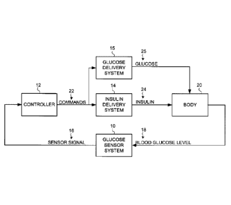
function.
[0028] Particular embodiments include a glucose sensor system 10, a
controller 12, an insulin delivery system 14 and a glucose delivery system 15,
as
shown in FIG. 1. Glucose sensor system 10 generates a sensor signal 16
representative of blood glucose levels 18 in body 20, and provides sensor
signal 16
to controller 12. Controller 12 receives sensor signal 16 and generates
commands
22 that are communicated to insulin delivery system 14 and/or glucose delivery
system 15. Insulin delivery system 14 receives commands 22 and may infuse
insulin 24 into body 20 in response to commands 22. Likewise, Glucose delivery
system 15 receives commands 22 and may infuse glucose 25 into body 20 in
response to commands 22.
[0029] Glucose sensor system 10 includes a glucose sensor, sensor
electrical components to provide power to sensor and generate the sensor
signal
16, a sensor communication system to carry sensor signal 16 to controller 12,
and a
sensor system housing for the electrical components and the sensor
communication
system.
[0030] Controller 12 may include electrical components and software to
generate commands for the insulin delivery system 14 and/or glucose delivery
18
CA 3006275 2018-05-25
system 15 based on sensor signal 16, and a controller communication system to
receive sensor signal 16 and carry commands to insulin delivery system 14
and/or
glucose delivery system 15. In particular implementations, controller 12 may
include a user interface and/or operator interface (not shown) comprising a
data
input device and/or a data output device. For example, such a data output
device
may generate signals to initiate an alarm, or a display or printer for showing
status
of the controller 12 and/or a patient's vital indicators. Such a data input
device may
comprise dials, buttons, pointing devices, manual switches, alphanumeric keys
and/or the like for receiving user and/or operator inputs. It should be
understood,
however, that these are merely examples of an input and output devices that
may
be a part of an operator and/or user interface, and that claimed subject
matter is not
limited in this respect.
[0031] Insulin delivery system 14 may include an infusion device and an
infusion tube to infuse insulin 24 into body 20. Similarly, glucose delivery
system 15
may include an infusion device and an infusion tube to infuse glucose 25 into
body
20. In alternative embodiments, insulin 24 and glucose 25 may be infused into
body
20 using a shared infusion tube. In yet another alternative embodiment,
insulin 24
and glucose 25 may be infused using an intravenous system for providing fluids
to a
patient in a hospital environment.
[0032] In particular embodiments, an infusion device includes infusion
electrical components to activate an infusion motor according to commands 22,
an
infusion communication system to receive commands 22 from controller 12, and
an
infusion device housing (not shown) to hold the infusion device.
19
CA 3006275 2018-05-25
[0033] In particular embodiments, controller 12 may be housed in an
infusion
device housing, and an infusion communication system may comprise an
electrical
trace or a wire that carries commands 22 from controller 12 to the infusion
device.
In alternative embodiments, controller 12 may be housed in a sensor system
housing and the sensor communication system may comprise an electrical trace
or
a wire that carries the sensor signal 16 from sensor electrical components to
controller electrical components. In other alternative embodiments, controller
12 has
its own housing or is included in a supplemental device. In another
alternative
embodiment, controller 12 is located with an infusion device and a sensor
system all
within one housing. In further alternative embodiments, the sensor,
controller,
and/or infusion communication systems may utilize a cable, a wire, fiber optic
lines,
RF, IR, or ultrasonic transmitters and receivers, and/or the like instead of
electrical
traces.
System Overview
[0034] Particular embodiments may include a sensor 26, a sensor set 28,
a
telemetered characteristic monitor 30, a sensor cable 32, an infusion device
34, an
infusion tube 36, and an infusion set 38, all worn on the body 20 of a user or
patient,
as shown in FIG. 2. Telemetered characteristic monitor 30 includes a monitor
housing 31 that supports a printed circuit board 33, batteries 35, antenna
(not
shown), and a sensor cable connector (not shown), as seen in FIGs. 3(a) and
3(b).
A sensing end 40 of the sensor 26 has exposed electrodes 42 and is inserted
through skin 46 into a subcutaneous tissue 44 of a user's body 20, as shown in
CA 3006275 2018-05-25
FIGs. 3(d) and 4. Electrodes 42 are in contact with interstitial fluid (ISF)
that is
present throughout subcutaneous tissue 44. Sensor 26 is held in place by
sensor
set 28, which is adhesively secured to the user's skin 46, as shown in FIGs.
3(c)
and 3(d). Sensor set 28 provides for a connector end 27 of sensor 26 to
connect to
a first end 29 of sensor cable 32. A second end 37 of sensor cable 32 connects
to
monitor housing 31. Batteries 35 included in monitor housing 31 provide power
for
sensor 26 and electrical components 39 on printed circuit board 33. Electrical
components 39-sample sensor signal 16 and store digital sensor values (Dsig)
in a
memory and then periodically transmit the digital sensor values Dsig from the
memory to controller 12, which is included in the infusion device.
[0035] Controller 12 processes the digital sensor values Dsig and
generates
commands 22 for infusion device 34. Infusion device 34 may respond to commands
22 and actuate a plunger 48 that forces insulin 24 out of a reservoir 50
located
inside the infusion device 34, as shown in FIG. 5. Glucose may be infused from
a
reservoir responsive to commands 22 using a similar device (not shown). In
alternative implementations, glucose may be administered to a patient orally.
[0036] In particular embodiments, a connector tip 54 of reservoir 50
extends
through infusion device housing 52 and a first end 51 of infusion tube 36 is
attached
to connector tip 54. A second end 53 of infusion tube 36 connects to infusion
set 38.
Insulin 24 is forced through infusion tube 36 into infusion set 38 and into
body 16.
Infusion set 38 is adhesively attached to the user's skin 46, as shown in FIG.
6. As
21
CA 3006275 2018-05-25
part of infusion set 38, a cannula 56 extends through skin 46 and terminates
in
subcutaneous tissue 44 completing fluid communication between the reservoir 50
and subcutaneous tissue 44 of the user's body 16.
[0037] In alternative embodiments, as pointed out above, a closed-loop
system in particular implementations can be a part of a hospital-based glucose
management system. Given that insulin therapy during intensive care has been
shown to dramatically improve wound healing, reduce blood stream infections,
renal
failure, and polyneuropathy mortality, irrespective of whether subjects
previously
had diabetes (See Van den Berghe G. et al. NEJM 345:1359-67, 2001), particular
implementations can be used in a hospital setting to control the blood glucose
level
of a patient in intensive care. In these alternative embodiments, since an
intravenous (IV) hookup may be implanted into a patient's arm while the
patient is in
an intensive care setting (e.g., ICU), a closed loop glucose control can be
established which piggy-backs off the existing IV connection. Thus, in a
hospital
based system, IV catheters which are directly connected to a patient vascular
system for purposes of quickly delivering IV fluids, can also be used to
facilitate
blood sampling and direct infusion of substances (e.g. insulin, glucose,
anticoagulants) into the intra-vascular space. Moreover, glucose sensors may
be
inserted through the IV line to give real-time glucose levels from the blood
stream.
Therefore, depending on the type of hospital-based system, the alternative
embodiments would not necessarily need the described system components such
as the sensor 26, the sensor set 28, the telemetered characteristic monitor
30, the
22
CA 3006275 2018-05-25
sensor cable 32, the infusion tube 36, and the infusion set 38- Instead,
standard
blood glucose meters or vascular glucose sensors as described in co-pending
U.S.
Patent Appl. Ser. No. 12/121,647, filed May 15, 2008, can be used to provide
the
blood glucose values to the infusion pump control and the existing IV
connection
can be used to administer the insulin to the patient.
[0038] It
is important to appreciate that numerous combinations of devices in
the hospital-based system can be used with a closed loop controller as
described
herein. For example, an auto blood glucose/intravenous insulin infusion system
can
automatically withdraw and analyze blood for glucose concentration at fixed
intervals (e.g., 5-20 minutes), extrapolate blood glucose values at a more
frequent
interval (e.g., one minute), and use the extrapolated signal for calculating
an IV-
insulin and/or glucose infusion according to a controller. It is important to
appreciate that numerous combinations of devices in the hospital-based system
can
be used with a closed loop controller according to particular embodiments. For
example, as described in FIG. 39b compared to the system shown in FIG. 39a, an
auto blood glucose/intravenous insulin and/or glucose infusion system can
automatically withdraw and analyze blood for glucose concentration at fixed
intervals (e.g., 5-20 minutes), extrapolate the blood glucose values at a more
frequent interval (e.g., one minute), and use the extrapolated signal for
calculating
an iv-insulin infusion according to the controller described below. The
modified auto
blood glucose/intravenous insulin infusion system may then eliminate the need
for
subcutaneous sensor compensation and subcutaneous insulin compensation (as
described with regards to a lead-lag compensator below). Such automatic
23
CA 3006275 2018-05-25
withdrawal of blood, and subsequent glucose determination can be accomplished
with existing technology (e.g., VIA, Biostator and/or like blood glucose
analyzer) or
by the system shown in FIG. 40. Here, the system shown in FIG. 40 uses a
peristaltic pump 420 to withdraw blood across an amperometric sensor 410
(e.g.,
such as that of sensor 26) and then returns the blood with added flush (0.5 to
1.0
ml) from the reservoir 400. Such a flush can consist of any makeup of saline,
heparin, glucose solution and/or the like. If the blood samples are obtained
at
intervals longer than 1.0 minute but less than 20 minutes, the blood glucose
determinations can be extrapolated on a minute-to-minute basis with
extrapolation
based on the present (n) and previous values (n-1) to work with the logic of
the
controller as described in detail below. For blood samples obtained at
intervals
greater than 20 minutes, a zero-order-hold may be used for extrapolation.
Based on
these blood glucose values, an infusion device can administer insulin and/or
glucose based, at least in part, on the closed loop controller described
below.
[0039] In other modifications, a manual blood-glucose/intravenous
insulin
system can be used where frequent manual entry of blood-glucose values or
blood-
glucose reference measurements from a standard blood glucose meter (e.g. YSI,
Beckman, etc) and extrapolate the values at more frequent intervals (e.g., 1.0
min)
to create a surrogate signal for calculating IV insulin infusion.
Alternatively, a
sensor blood glucose/intravenous insulin system can use a continuous glucose
sensor (e.g. vascular, subcutaneous, etc.) for frequent blood glucose
measurement.
Moreover, insulin can be administered subcutaneously rather than intravenously
in
24
CA 3006275 2018-05-25
any one of the previous examples according to controller embodiments described
below.
[0040] In still further alternative embodiments, system components may
be
combined in a smaller or greater number of devices and/or the functions of
each
device may be allocated differently to suit the needs of the user.
Controller
[0041] Once hardware for a closed loop system is configured, as
described
above, the effects of the hardware on a human body are determined by the
controller. In particular embodiments, controller 12 is designed to model a
pancreatic beta cell (13-cell). In other words, controller 12 commands
infusion device
34 to release insulin 24 into body 20 at a rate that causes the insulin
concentration
in the blood to follow a similar concentration profile as would be caused by
fully
functioning human 13-cells responding to blood glucose concentrations in the
body
20.
[0042] A controller that simulates the body's natural insulin response
to blood
glucose levels not only makes efficient use of insulin but also accounts for
other
bodily functions as well since insulin has both metabolic and mitogenic
effects.
Controller algorithms that are designed to minimize glucose excursions in the
body
without regard for how much insulin is delivered may cause excessive weight
gain,
hypertension, and atherosclerosis. In particular embodiments, controller 22 is
intended to emulate the in vivo insulin secretion pattern and to adjust this
pattern to
CA 3006275 2018-05-25
be consistent with in vivo 13-cell adaptation. The in vivo 13-cell response in
subjects
with normal glucose tolerance (NGT), with widely varying insulin sensitivity
(SI), is
the optimal insulin response for the maintenance of glucose homeostasis.
13-Cell and PID Control
[0043] In vivo 13-cell response to changes in glucose may be
characterized by
"first" and "second" phase insulin responses. This biphasic insulin response
is
clearly seen during hyperglycemic clamps applied to NGT subjects, as shown in
FIG. 23(b). During a hyperglycemic clamp the glucose level is rapidly
increased
from a basal level GB to a new higher level Gc and then held constant at the
higher-
level Gc as shown in FIG. 23(a). The magnitude of the increase in glucose
(LIG)
affects the insulin response. Four insulin response curves are shown for four
different glucose clamp levels in FIG. 23 (b).
[0044] According to an embodiment, a biphasic insulin response of a 13-
cell
can be modeled using components of a proportional, plus integral, plus
derivative
(PID) controller. A PID controller may be selected since PID algorithms are
stable
for a wide variety of non-medical dynamic systems, and PID algorithms have
been
found to be stable over widely varying disturbances and changes in system
dynamics.
[0045] The insulin response of 13-cells during a hyperglycemic clamp is
diagrammed in FIGS. 24(a-e) using the components of a PID controller to model
the
13-cell. A proportional component Up and a derivative component Up of the PID
controller may be combined to represent a first phase insulin response 440,
which
26
CA 3006275 2018-05-25
lasts several minutes. An integral component 1.1, of the PID controller may
represent
a second phase insulin response 442, which is a steady increase in insulin
release
under hyperglycemic clamp conditions. The magnitude of each component's
contribution to the insulin response is described by the following equations:
Proportional Component Response: Up K p (G ¨ GB);
Integral Component Response: U, = K (G ¨ G B)dt + I B ; and
to
Derivative Component Response: UD=KD¨dG.
dt
Where:
Up is the proportional component of the command sent to the insulin delivery
system;
U, is the integral component of the command sent to the insulin delivery
system;
Up is the derivative component of the command sent to the insulin delivery
system;
Kp is a proportional gain coefficient;
K, is a integral gain coefficient;
Kp is a derivative gain coefficient;
G is a present blood glucose level;
GB is a desired basal glucose level;
t is the time that has passed since the last sensor calibration;
to is the time of the last sensor calibration; and
27
CA 3006275 2018-05-25
IB is a basal insulin concentration at to or can also be described as U1 (to)
[0046] The combination of the PID components that model the two phases
of
insulin response by a 6-cell is shown in FIG. 24(e) as it responds to the
hyperglycemic clamp of FIG. 24(a). FIG. 24(e) shows that the magnitude of the
first
phase response 440 is driven by the derivative and proportional gains, KD and
Kp.
And the magnitude of the second phase response 442 is driven by the integral
gain
[0047] According to an embodiment, the aforementioned components of the
PID response may be computed at set sample intervals and/or command cycles to
provide control commands (e.g., to insulin delivery system 14 and/or glucose
delivery system 15). In the expression of the integral component response
above, it
should be observed that glucose level G is a function of time (t). Here, to
address
undue effects to the integral component response for extremely long sample
intervals and/or command cycles (e.g., one hour or longer), the integration
interval t
¨ to of the integral component response may be limited to a set maximum
integration time. In particular embodiments, such a maximum integration time
may
be set to a maximum sample interval or maximum duration between consecutive
PID commands.
[0048] According to an embodiment, the value of ¨is determined based on
dt
consecutive blood glucose samples and/or estimates obtained from a blood
glucose
sensor (e.g., glucose sensor system 10). For example, the value of ¨dG may be
dt
28
CA 3006275 2018-05-25
estimated based upon the difference between consecutive blood glucose sensor
samples divided by the time interval between such samples and/or estimates. In
using this particular technique, errors in estimating ¨dG may be pronounced if
such a
dt
time interval between samples and/or estimates is very small. Here, in a
particular
embodiment, a minimum time interval between samples and/or estimates, for
purpose of estimating ¨dG may be established to limit the effect of very short
time
dt
intervals between samples in estimating dt dG . In one alternative
implementation, if
consecutive blood glucose samples and/or estimates are obtained at times that
are
apart less than such a minimum time interval, non-consecutive blood glucose
samples and/or estimates may be selected for the purpoSe of estimating ¨dG.
dt
[0049] The components of the PID controller can also be expressed in
its
discrete form and follows:
Proportional Component Response: PI = K p(SG; Gs.p);
Integral Component Response: Icnon = I + K 1(SG; ¨ G sp), IL = ; and
Derivative Component Response: D,, = K DdGdt fn .
[0050] Where Kp, Ki, and KD are the proportional, integral, and
derivative gain
coefficients, respectively, SGf and dGdtf are the filtered sensor glucose and
derivative respectively, and the superscript n refers to discrete time. In a
particular
embodiment, a controller may provide one or more "PID commands" on a discrete
29
CA 3006275 2018-05-25
command cycle n based, at least in part, on the values of Pcnon,1 cnoõ and
131. Thus,
for a "current" command cycle n, an associated PID command may be based, at
least in part, on the values of PC'?,, I,, and DL. Likewise, for a
"subsequent"
command cycle n+1, an associated command cycle may be based, at least in part,
on the values of pi icno+ni and Dc"o+ni . In a particular implementation, for
example,
such a PID command may comprise a combination of Pcn/,non and D :on such as
Pcnon + I D:on It should be understood, however that this merely an example
of
how a PID command may be determined for a particular command cycle and that
claimed subject matter is not limited in this respect.
[0051] According to an embodiment, an acute insulin response may prevent
wide postprandial glycemic excursions. An early insulin response to a sudden
increase in glucose level may result in less total insulin being needed to
bring the
glucose level back to a desired basal glucose level. This is because an
infusion of
insulin may increase the percentage of glucose that is taken up by the body.
Infusing a large amount of insulin to increase the percentage of glucose
uptake
while the glucose concentration is high may result in an efficient use of
insulin.
Conversely, infusing a large amount of insulin while the glucose concentration
is low
results in using a large amount of insulin to remove a relatively small amount
of
glucose. In other words, a larger percentage of a big number is more than a
larger
percentage of a small number. The infusion of less total insulin helps to
avoid
development of insulin resistance in the user. As well, first-phase insulin is
thought
to result in an early suppression of hepatic glucose output.
CA 3006275 2018-05-25
[0052] Insulin sensitivity is not fixed and can change dramatically in
a body
depending on the amount of exercise by the body. In one study, for example,
insulin responses in highly exercise-trained individuals (individuals who
trained
more than five days a week) were compared to the insulin responses in subjects
with normal glucose tolerance (NGT) during a hyperglycemic clamp. The insulin
response in exercise-trained individuals 444 was about 1/2 of the insulin
response
of the NGT subjects 446, as shown in FIG. 25(a). But the glucose uptake rate
for
each of the individuals (exercise-trained 448 or normal 450) was virtually
identical,
as shown in FIG. 25(b). Thus, it can be speculated that the exercise-trained
individuals have twice the insulin sensitivity and half of the insulin
response leading
to the same glucose uptake as the NGT individuals. Not only is the first phase
insulin response 440 reduced due to the effects of exercise, but the second
phase
insulin response 442 has also been shown to adjust to insulin sensitivity, as
can be
seen in FIG. 25(a).
[0053] In particular embodiments, a closed loop control system may be
used
for delivering insulin to a body to compensate for 13-cells that perform
inadequately.
There is a desired basal blood glucose level GB for a particular body. The
difference
between the desired basal blood glucose level GB and an estimate of the
present
blood glucose level G is the glucose level error GE that is to be corrected.
In a
particular embodiment, glucose level error GE is provided as an input to the
controller 12, as shown in FIG. 26.
[0054] If the glucose level error GE is positive (meaning that the
present
estimate of the blood glucose level G is higher than the desired basal blood
glucose
31
CA 3006275 2018-05-25
level GB) then a command from controller 12 may generate a PID command to
drive
insulin delivery system 34 to provide insulin 24 to body 20. Likewise, if GE
is
negative (meaning that the present estimate of the blood glucose level G is
lower
than the desired basal blood glucose level GB) then a command from controller
12
may generate a PID command to drive glucose delivery system 35 to provide
glucose 25 to body 20. In terms of the control loop, glucose may be considered
to
be positive, and therefore insulin is negative. Sensor 26 may sense an ISF
glucose
level and generate a sensor signal 16. Sensor signal 16 is filtered and
calibrated to
create an estimate of the present blood glucose level. In particular
embodiments,
an estimate of the present blood glucose level G may be adjusted with
correction
algorithms before it is compared to the desired basal blood glucose level GB
to
calculate a new glucose level error GE to start the loop again.
[0055] If the glucose level error GE is negative (meaning that the
present
estimate of the blood glucose level is lower than the desired basal blood
glucose
level GB) then controller 12 reduces or stops the insulin delivery depending
on
whether the integral component response of the glucose error GE is still
positive. In
alternative embodiments, as discussed below, controller 12 may initiate
infusion of
glucose 25 if glucose level error GE is negative.
[0056] If the glucose level error GE is zero, (meaning that the
present
estimate of the blood glucose level is equal to the desired basal blood
glucose level
GB) then the controller 12 may or may not issue commands to infuse insulin 24
or
glucose 25 depending on the derivative component (whether the glucose level is
32
CA 3006275 2018-05-25
raising or falling) and the integral component (how long and by how much
glucose
level has been above or below the basal blood glucose level GB).
[0057] To more clearly understand the effects that the body has on the
control loop, a more detailed description of the physiological affects that
insulin has
on the glucose concentration in the interstitial fluid (ISF) is provided. In
particular
embodiments, infusion delivery system 34 delivers insulin into the ISF of
subcutaneous tissue 44 of the body 20. Alternatively, insulin delivery system
34 or
a separate infusion device (not shown) may similarly deliver glucose into the
ISF of
subcutaneous tissue 44. Here, insulin may diffuse from the local ISF
surrounding
the cannula into the blood plasma and then spread throughout the body 20 in
the
main circulatory system. Infused insulin may then diffuse from the blood
plasma
into the interstitial fluid ISF substantially through out the entire body.
Here, insulin
24 binds with and activates membrane receptor proteins on cells of body
tissues.
This facilitates glucose permeation into the activated cells. In this way, the
tissues of
the body 20 take up the glucose from the ISF. As the ISF glucose level
decreases,
glucose diffuses from the blood plasma into the ISF to maintain glucose
concentration equilibrium. Finally, the glucose in the ISF permeates the
sensor
membrane and affects the sensor signal 16. .
[0058] In addition, insulin has direct and indirect affects on liver
glucose
production. Increased insulin concentration decreases liver glucose
production.
Therefore, acute and immediate insulin response not only helps the body to
efficiently take up glucose but also substantially stops the liver from adding
to the
glucose in the blood stream. In alternative embodiments, as pointed out above,
33
CA 3006275 2018-05-25
insulin and/or glucose may be delivered more directly into the blood stream
instead
of into the interstitial fluid, such as delivery into veins, arteries, the
peritoneal cavity,
or the like. Accordingly, any time delay associated with moving insulin and/or
glucose from the interstitial fluid into the blood plasma is diminished. In
other
alternative embodiments, the glucose sensor is in contact with blood or body
fluids
other than interstitial fluid, or the glucose sensor is outside of the body
and
measures glucose through a non-invasive means. The embodiments that use
alternative glucose sensors may have shorter or longer delays between the
blood
glucose level and the measured blood glucose level.
Selecting Controller Gains
[0059] In particular embodiments, controller gains Kp, K/, and KD, are
selected so that the commands from the controller 12 direct infusion device 34
to
release insulin 24 into the body 20 at a rate, that causes the insulin
concentration in
the blood to follow a similar concentration profile, as would be caused by
fully
functioning human 13-cells responding to blood glucose concentrations in the
body.
Similarly, controller gains Kp, K1, and KD, may be selected so that the
commands
from the controller 12 direct infusion device 34 to release glucose 25 in
response to
insulin excursions. In particular embodiments, the gains may be selected by
observing the insulin response of several normal glucose tolerant (NGT)
individuals,
with healthy normally functioning 13-cells. A first step in determining a set
of
controller gains is to take periodic measurements of blood glucose and blood
insulin
concentrations from the group of NGT individuals. Second, each individual in
the
group may be subjected to a hyperglycemic clamp, while continuing to
periodically
34
CA 3006275 2018-05-25
measure and record the blood glucose and blood insulin concentrations. Third,
a
least squares curve fit may be applied to the recorded blood insulin
concentrations
measured over time for each individual. The result is a set of curves
representing
the insulin responses to the hyperglycemic clamp for each individual of the
group.
Fourth, the curves may be used to calculate the controller gains Kp, K1, and
KD, for
each individual. Finally, proportional gains from each of the individuals may
be
averaged together to obtain an average proportional gain, Kp, to be used in
controller 12. Similarly, integral gains, K1, and the derivative gains, KD,
may be
averaged to obtain an average integral gain, K1, and an average derivative
gain, KD,
for controller 12. Alternatively, other statistical values may be used instead
of
averages such as, for example, maximums, minimums, the high or low one, two or
three sigma standard deviation values, and/or the like. The gains calculated
for
various individuals in a group may be filtered to remove anomalous data points
before statistically calculating the gains to be used in a controller.
[0060] In one particular example, a least squares curve-fitting method
was
used to generate representative insulin response curves from two fasted
individuals
in a group, as shown in FIGs. 27 and 28. Then, controller gains were
calculated
from insulin response curves of the two representative individuals and are
shown in
Table 1. When calculating the controller gains, the insulin clearance rate (k)
was
assumed to be 10 (ml of insulin)/min/(kg. of body weight). Here, the insulin
clearance rate k is the rate that insulin is taken out of the blood stream in
a body.
Finally, the average value for each type of gain is calculated using the
measurements from the group, as shown in Table 1.
CA 3006275 2018-05-25
PID Controller Gains Calculated from the Insulin Response Curves of Two NGT
Individuals
Individuals Proportional Gain, Integral Gain, K, Derivative
Gain,
Kp KD
a 0.000406 0.005650 0.052672
0.000723 0.003397 0.040403
Average 0.000564 0.004523 0.046537
TABLE 1
[0061] Controller gains may be expressed in various units and/or may be
modified by conversion factors depending on preferences for British or S. I.
Units,
floating-point or integer software implementation, the software memory
available,
and/or the like. The set of units for the controller gains for the particular
implementation of Table 1 is:
Kp: (mU of insulin)/min/(Kg of body weight) per (mg of glucose)/(dl of
plasma);
K/: (mU of insulin)/min/(Kg of body weight) per (mg of glucose)/(dI of
plasma)/min.; and
KD: (mU of insulin)/min/(Kg of body weight) per (mg of glucose)/(dl of
plasma)*min.
[0062] In alternative embodiments, other curve fitting methods may be
used
to generate insulin response curves from the measurements of blood insulin
concentrations.
[0063] An estimate of an insulin clearance rate (k), the individual's
body
weight (W), and the insulin sensitivity Si may be used to calculate controller
gains
from insulin response curves for each NGT individual. The insulin clearance
rate (k)
36
CA 3006275 2018-05-25
may be substantially proportional to body weight and is well documented in
literature. An individual's insulin sensitivity Si may be measured using an
intravenous glucose tolerance test, a hyperinsulinemic clamp, or in the case
of a
diabetic patient, comparing the individual's daily insulin requirement to the
individual's daily carbohydrate intake.
[0064] In particular embodiments, two parameters, insulin sensitivity
Si and
insulin clearance rate k, may be measured for each individual. In other
embodiments, an insulin clearance rate k may be estimated from literature
given an
individual's body weight. In other particular embodiments, longer or shorter
insulin
clearance times may be used. In still other embodiments, all of the parameters
are
estimated. In additional embodiments, one or more parameters are measured,
while at least one parameter is estimated from literature.
[0065] In other alternative embodiments, controller gains may be
calculated
using a group of individuals with similar body types. For example, an insulin
response to a hyperglycemic clamp may be measured for several tall, thin, NGT,
males in order to calculate the controller insulin response gains for each
individual
in the group. Then, gains may be statistically combined to generate a set of
representative controller gains for tall, thin, NGT, males. The same could be
done
for other groups such as, but not limited to, short, heavy, NGT, females;
medium
height, medium weight, highly exercised trained, females; average height and
weight ten year olds; and/or the like. Then, controller gains may be selected
for
each individual user based on the group that best represents the individual.
In
further alternative embodiments, controller gains may be uniquely selected for
each
37
CA 3006275 2018-05-25
individual user. In particular embodiments, controller gains for a user may be
selected based on measurements of insulin sensitivity, insulin clearing time,
insulin
appearance time, insulin concentration, body weight, body fat percentage, body
metabolism, or other body characteristics such as pregnancy, age, heart
conditions,
and/or the like.
[0066] In other alternative embodiments, the controller gains are
estimated
as a function of a user's body weight Wand insulin sensitivity Si. A series of
observations are used to justify this method. In a first observation,
controller gains
may be proportional to one another. For example, small changes in glucose
concentration may cause a small derivative response UD, a small proportional
response Up and a small integral response U. Also, larger changes in glucose
concentration cause a proportionally larger derivative response UD, a
proportionally
larger proportional Up response and a proportionally larger integral response
1.11, as
shown in FIG. 23(b). Changes in glucose concentration may proportionally
affect all
three components of a controller response Upo. In a second observation, a
first
phase insulin response (0) may be proportional to the derivative gain KD. In a
third observation, two constants may be readily obtained form information in
published literature or may be measured from a cross-section of the general
population. The two constants are the insulin clearance rate k for a human
given a
body weight Wand the disposition index (DI) for a human given a change in
glucose concentration.
[0067] While multiple sources for the information may be used to
calculate
the insulin clearance rate k, one source is the article "Insulin clearance
during
38
CA 3006275 2018-05-25
hypoglycemia in patients with insulin-dependent diabetes mellitus", written by
Kollind M et al., published in Horm Metab Res, 1991 July; 23(7):333-5. Here,
the
insulin clearance rate k may be obtained from insulin infused divided by the
steady
state plasma insulin concentration. An insulin clearance constant Ak, which is
independent of an individual's body weight, may be obtained by dividing the
insulin
clearance rate k (measured from a particular individual) by the individual's
body
weight. An insulin clearance constant Ak may be assumed to be about the same
for
all humans, except under extenuating circumstances such as after an individual
has
contracted HIV, other metabolic affecting diseases, and/or the like.
[0068] The disposition index DI for a human given a change in glucose
concentration may be available from information presented in the article
"Quantification of the relationship between insulin sensitivity and beta-cell
function
in human subjects. Evidence for a hyperbolic function", written by Khan S E et
al.,
published in Diabetes, 1993 November; 42(11):1663-72.
[0069] Both, the disposition index DI and the insulin clearance rate k
may be
measured directly from tests. The disposition index DI may be calculated given
the
first phase insulin response measured form a glucose clamp test and the
individual's insulin sensitivity measured from an insulin sensitivity test.
The insulin
clearance rate k may be measured from an insulin clearance test. The glucose
clamp test and the insulin clearance test are described in the above-mentioned
articles and are well known in the art. An insulin sensitivity S1 may be
measured
using an intravenous glucose tolerance test or a hyperinsulinemic clamp test.
39
CA 3006275 2018-05-25
[0070] Given these observations, then the following parameters may be
measured from an NGT individual's insulin response to a glucose clamp: a
desired
first phase insulin response cpi, the ratio of KD to Kp, and the ratio of KD
to Kb Then
the derivative gain KD may be calculated from the first phase insulin response
(pi
using the constants k and DI. Finally Kp and K1 may be calculated using the
ratios
of KD to Kp and KD to
[0071] The first phase insulin response cp1 may be observed in a NGT
individual as the area under the insulin response curve during approximately
the
first ten minutes of such a glucose clamp. An increase in glucose
concentration
during the glucose clamp may be expressed as:
where G is equal to Gc, the glucose concentration during the clamp, and GB is
the
basal glucose concentration before the clamp.
[0072] The role of the first phase insulin response (p1 has been
emphasized
by studies indicating that, in NGT subjects, the product of first phase
insulin
response cp1 and insulin sensitivity (SI) is a constant known as the
disposition index
as follows:
DI = (pi Si.
[0073] Accordingly,
, DI
(y1=¨
S,
CA 3006275 2018-05-25
For a different AG there is a different cp1 and therefore a different DI. But,
the ratio
DI/AG may be substantially constant even for different individuals with
different
insulin sensitivities.
[0074] Insulin sensitivity S, may be defined as the percentage of the
glucose
concentration that the body tissues will take up for a given amount of
insulin. Ap-
cell may naturally adapt to changes in insulin sensitivity by adjusting an
amount of
insulin it secretes during the first phase insulin response cp1. This suggests
that the
body may naturally seek an optimal level of glucose tolerance. A controller
that
mimics this characteristic of a 13-cell may more accurately simulate a body's
natural
insulin response.
[0075] The instantaneous insulin response (RI) may be calculated given
the
insulin clearance rate (k) and the first phase insulin response 91,
IR/=
[0076] As pointed out above, an insulin clearance rate k may be
proportional
to body weight W. Therefore substituting a proportional constant Ak and the
user's
body weight Wfor k and replacing 91 with the ratio of DI over S1yields the
following:
DI
= /1,u
[0077] The instantaneous insulin response R, may also be expressed as
the
product of the derivative gain KD and the change in glucose concentration AG
as
follows:
=KDAG.
41
CA 3006275 2018-05-25
[0078] Setting the two expressions for Ri equal to each other and
solving for
KD yields the following:
KD =WAk2DI .
S 1AG
[0079] As mentioned above, DI/AG and Ak may be treated as constants
available or calculated from data in published literature. Such constants may
be
combined and reduced to a single constant, Q, as follows:
QAkDI
= __ =
AG
This may provide an expression for the derivative gain KD that is a function
of the
user's body weight Wand the user's insulin sensitivity Si as follows:
KD = ¨WQ .
S
[0080] Here, once derivative gain KD is determined, proportional and
integral
gains may be calculated using ratios. A ratio of KD/Kp can be set to the
dominant
time constant for insulin action, ranging from 10-60 minutes, but more
typically 20-
40 minutes (e.g., 30 minutes). For example, calculating Kp given KD using a
time
constant of 30 minutes, may provide the following relationship:
K D K D
JV Kp
[0081] In a similar fashion, the ratio of KD/K, can be set to the
average ratio
measured from a population of NGT individuals. Also, Ki can be calculated from
KD.
[0082] In particular embodiments, an individual may enter a patient's
body
weight Wand insulin sensitivity Si into a device containing the controller.
Controller
42
CA 3006275 2018-05-25
gains may then be automatically calculated and used by the controller. In
alternative embodiments, an individual may enter a patient's body weight Wand
insulin sensitivity S1 into a device and the device provides the information
to the
controller to calculate the gains.
[0083] A study was conducted to confirm that the insulin response for
an
individual could be reproduced using the glucose sensor as an input. In the
study,
glucose and insulin measurements were taken while a hyperglycemic clamp was
applied to a NGT individual. The glucose level measurements, shown in FIG.
29(a),
were used as the inputs to a mathematical model created to simulate a PID
insulin
response controller. The insulin dosing commanded by the controller in
response to
the glucose clamp very closely approximates the actual insulin appearance in
the
NGT individual, as shown in FIG. 29(b). The insulin concentration measured
from
periodic blood samples 456 taken from the individual during the test are
represented by dots in FIG. 29(b). The output from the mathematical model
simulating the insulin response commanded by the controller is shown as a
solid
line 458 in FIG. 29(b).
[0084] Three different devices were used to measure the individual's
blood
glucose during the study. Blood glucose meter readings 460 from periodic blood
samples taken from the individual are represented by the dots in FIG. 29(a).
Two
MiniMed sensors (such as those described below) were placed in the
individual's
subcutaneous tissue, and the sensor readings 462, 464 are shown as lines in
FIG.
29(a). The sensor readings 462, 464 are slightly delayed compared to the meter
readings 460. The delay is most likely due to the delay between blood glucose
and
43
CA 3006275 2018-05-25
interstitial fluid (ISF) glucose and can be substantially corrected through
the use of a
filter if needed. In this study, the delay was not corrected by a filter and
did not
significantly affect the controller's ability to command an insulin response
that
matches the natural response of the NGT individual. This study indicates that
the
PID insulin response controller model is a good minimal model of insulin
secretion
that captures the biphasic response of healthy 13-cells. Correction of the
delay is
only expected to increase the accuracy of the model.
Fuzzy Logic to Select Between Multiple Sets of Controller Gains
[0085] In
particular referred embodiments, one set of controller gains is used
for a particular individual. In alternative embodiments, more than one set of
controller gains is used, and fuzzy logic is used to select between and/or
among
sets of controller gains and to determine when to change from one set of
controller
gains to another. In particular alternative embodiments, controller gains are
different
if the glucose level is above or below the desired glucose basal level. In
other
alternative embodiments, the controller gains are different if the glucose
level is
increasing or decreasing. A justification for different sets of gains comes
from
physiological studies that indicate that 13-cells turn off faster than they
turn on. In still
other alternative embodiments, controller gains are different depending on
whether
the glucose level is above or below the desired glucose basal level and
whether the
glucose level is increasing or decreasing, which results in four sets of
controller
gains. In additional alternative embodiments, controller gains may change
depending on the magnitude of the hypoglycemic excursion. In other words, the
44
CA 3006275 2018-05-25
controller gains for small changes in glucose are different than those for
large
changes in glucose.
Self-Tuning Controller Gains
[0086] Further embodiments may include a controller that self tunes one
or
more the gains, Kp, Ki and KD, to accommodate changes in insulin sensitivity.
In
particular embodiments, previous measurements of glucose levels are compared
to
the desired basal glucose level GB. For example, desired basal glucose level
GB is
subtracted from previous glucose level measurements. Then any negative values,
within a predefined time window, are summed (in essence integrating the
glucose
level measurements that were below the basal glucose level GB). If the
resulting
sum is greater than a pre-selected hypoglycemic integral threshold, then the
controller gains are increased by a factor (1+ a). Conversely, if the integral
of the
glucose level measurements that were measured above the basal glucose level GB
within the predefined time window is greater than a pre-selected hyperglycemic
integral threshold, then the controller gains are decreased by a factor (1-a).
[0087] In particular embodiments, a predefined time window over which
the
glucose concentration integrals are evaluated may be set at 24 hours, and
controller gains may be adjusted if needed at the end of each such predefined
time
window. In alternative embodiments, integrals of the glucose level
measurements
may be continuously calculated over a moving window of time, and if either
integral
exceeds a threshold, the gains may be immediately adjusted. In particular
embodiments, such a moving time window may be one hour, and the time window
may be restarted whenever the gains are adjusted. In other alternative
CA 3006275 2018-05-25
embodiments, the time window may be longer or shorter depending on the sensor
accuracy, the rate at which an individual's insulin sensitivity changes, the
computational capabilities of the hardware and/or the like.
[0088] In particular embodiments, the adjustment amount (a) is 0.01.
In
alternative embodiments, the adjustment amount a is greater or smaller
depending
on the sensor accuracy, the rate at which an individual's insulin sensitivity
changes,
the rate at which the sensor sensitivity S, changes, and/or the like. In still
other
alternative embodiments, adjustment amount a is made larger or smaller
depending
on the amount that the integral of the measured glucose levels exceeds a
threshold.
In this way, gains may be adjusted by greater amounts if the measured glucose
level G is significantly deviating from the desired blood glucose level GB and
less if
the measured glucose level G is closer to the desired blood glucose level GB.
In
additional alternative embodiments, the controller employs a Kalman filter to
establish glucose level G based on a series of blood glucose sensor
measurements.
Modifying the PID Controller to Incorporate an Integrator Leak
[0089] In particular embodiments, a PID control response was described
with
constant gain components, Kp, K, and KD. Although a control response may
guarantee zero steady-state error (i.e. steady state glucose minus a desired
basal
glucose (GB=0)), inherently, the integral component may destabilize feedback
control because there is no temporal wind down of the insulin response while
the
46
CA 3006275 2018-05-25
integral component models an increase in insulin response. Here, the integral
component may be expressed as follows:
= IC, (G ¨ G B)dt +U I (to) .
to
[0090] Without any correction, integral component U, may have a
tendency to
over-estimate an increase in the insulin response. Since a small difference
between
steady-state glucose and GB is typically acceptable in insulin response
control, an
alternative modeling of the integral component can incorporate an integrator
leak to
reduce the magnitude of the destabilizing effect. Specifically, changes in U,
(t) can
be described by a term proportional to the error in glucose and a term that
leaks in
proportion to the magnitude of U1. This can be shown by the following
expression:
dt
___________ =K1(G¨GB)¨KL Ul; with initial condition U, = U1(to).
dt
[0091] The parameter KLEAK is the reciprocal time constant of the rate
of
leaking (I-LEAK in min=1/KLEAK), where r LEAK is a tuning parameter that can
be set
based on empirical data, and be tied with the other gain components Kp, K, and
KD.
However, realization of an artificial 13-cell may have 2-L as a user input.
U, can
also be expressed in discrete form by standard methods.
Post-Controller (Lead/Lag) Compensator
[0092] In particular embodiments, commands may be issued from a
controller
without regard to where in the body the insulin delivery system is to infuse
the
insulin. In essence, the assumption is that the insulin is either delivered
directly into
47
CA 3006275 2018-05-25
the blood stream for immediate use by the body, or that any time delays caused
by
delivering the insulin somewhere in the body other than the blood stream can
be
compensated for by adjusting Kp, K, and/or KD. In this case, commands attempt
to
model a 13-cell insulin secretion profile, an example of which is shown in
FIG. 35(a).
Since 13-cells secrete insulin directly into the blood stream, the 13-cell
insulin
secretion profile is the intended blood plasma insulin concentration profile.
However, an insulin delivery delay may distort the intended blood plasma
insulin
concentration profile, as shown in FIG. 35(b). Here, an insulin delivery delay
is the
amount of time between the instant that the command is given to the insulin
delivery
system to infuse insulin and the time that insulin reaches the blood plasma.
An
insulin delivery delay may be caused by a diffusion delay, represented by a
circle
with an arrow 528 in FIG. 20, which is the time required for insulin that has
been
infused into a tissue to diffuse into the blood stream. Other contributors to
insulin
delivery delay may include, time for the delivery system to deliver the
insulin to the
body after receiving a command to infuse insulin, time for the insulin to
spread
through out the circulatory system once it has entered the blood stream,
and/or by
other mechanical or physiological causes. In addition, the body clears insulin
even
while an insulin dose is being delivered from the insulin delivery system into
the
body. Since insulin is continuously cleared from the blood plasma by the body,
an
insulin dose that is delivered to the blood plasma too slowly or is delayed is
at least
partially, if not significantly, cleared before the entire insulin dose fully
reaches the
blood plasma. Therefore, the insulin concentration profile in the blood plasma
never
achieves the same peak (nor follows the same profile) it would have achieved
if
48
CA 3006275 2018-05-25
there were no delay. Given an insulin dose delivered all at once into the
blood
plasma at time zero, an insulin concentration in the blood plasma is raised
virtually
instantaneously (not shown) and then would decrease exponentially over time as
the body clears (uses or filters out) the insulin, as shown in FIG. 36(a) per
the
following expression:
/0 -Pit
C p = -e ,
Vp
where:
Cp is the concentration of insulin in the blood plasma;
lo is a mass of the insulin dose delivered directly to the blood plasma at
time
zero;
Vp is a volume of the blood plasma in the body;
Pi is a reciprocal time constant for insulin clearance; and
t is the time that has passed since the delivery of the insulin dose directly
into
the blood plasma.
[0093] Time constant for insulin clearance P1 may be calculated as
follows:
k
V,
where:
k is the volume insulin clearance rate; and
Vp is a volume of the blood plasma in the body.
[0094] Alternatively, time constant for insulin clearance 1=', may be
obtained
by providing insulin to an individual that does not generate his own insulin,
and then
49
CA 3006275 2018-05-25
periodically testing blood samples from the individual for insulin
concentration.
Then, using an exponential curve fitting routine, generate a mathematical
expression for a best-fit curve for the insulin concentration measurements,
and
observe the time constant in the mathematical expression.
[0095] Given the same insulin dose (delivered at time zero all at once)
into
the subcutaneous tissue, instead of directly into the blood plasma, the
concentration
of insulin in the blood plasma may begin to rise slowly as insulin diffuses
from the
interstitial fluid ISF into the blood plasma, as shown in FIG. 36(b). At the
same time
that insulin is entering the blood plasma, the body may be clearing insulin
from the
blood. While the rate at which insulin is entering the blood plasma exceeds
the
insulin clearance rate, the insulin concentration in the blood plasma may
continue to
increase. If the insulin clearance rate exceeds the rate at which insulin is
entering
the blood plasma from the interstitial fluid ISF, the insulin concentration in
the blood
plasma may begin to decrease. So, the result of delivering insulin into the
interstitial
fluid ISF instead of directly into the blood stream is that the insulin
concentration in
the blood plasma is spread over time rather than increased virtually
instantaneously
to a peak followed by a decay.
[0096] The following bi-exponential expression may be used to model the
insulin concentration in blood plasma given an insulin dose delivered to the
subcutaneous tissue:
Cp = ____________ 10D (e-P2' ¨
VprisF(P3 ¨ P2)
where:
CA 3006275 2018-05-25
Cp is the concentration of insulin in the blood plasma;
lo is the mass of the insulin dose delivered to the subcutaneous tissue at
time
zero;
D is a diffusion coefficient (the rate at which insulin diffuses from the
interstitial fluid ISF into the blood glucose);
Vp is a volume of the blood plasma in the body;
VisF is a volume of interstitial fluid ISF that the insulin is delivered to;
P2 is a time constant;
P3 is a time constant greater than or equal to P2; and
t is time since the delivery of the insulin dose into the interstitial fluid
ISF.
[0097] Time constants may be calculated using the following quadratic
formula:
2
¨4a0
P25P3 =
2
where:
D + K D
VP V ISF
(D+KY D D2
ao=
Vp)\.VISF V ISFV P
[0098] In alternative embodiments, a post-controller lead-lag
compensator
522 may modify commands (e.g., Upo) to compensate for insulin delivery delay
and/or insulin clearance rate k, as shown in FIG. 37. Here, post-controller
lead-lag
compensator 522 may modify comments according to the following expression:
51
CA 3006275 2018-05-25
U COMP s+a
U PID +
Where:
1/a is a lead constant;
1/y is a lag constant;
s is the Laplace variable, and
Uccmp is the compensated commands calculated by the lead-lag
compensator 522.
[0099] A PID controller may generate commands (Upo) for a desired insulin
delivery rate and/or glucose delivery rate into the blood plasma. Commands
UpID
are calculated and issued periodically depending on the update rate for the
control
loop, which is selected based on a maximum anticipated rate of change of the
blood
glucose level, an insulin delivery system minimum insulin dosage, insulin
sensitivity,
a maximum and a minimum acceptable glucose concentration, or the like.
Commands Upo may be used as inputs to post-controller lead-lag compensator
522.
[00100] In particular embodiments, compensated commands (Ucomp) issued
from the post-controller lead-lag compensator 522 may use more than one value
from the controller. In particular embodiments, post-controller lead-lag
compensator
522 may use a present command (Upon) provided in a current command cycle and
a command (Upon provided in a previous command cycle to calculate a
compensated command UCOMP per a compensation expression as follows:
U
n
U COMP '= (1¨ 7)U COMPn-1 j_ T T
m PID + (1¨ a)U pip" ,
52
CA 3006275 2018-05-25
where:
Upon is the command provided in and/or associated with the current
command cycle;
Upon-1 is the command provided in and/or associated with the previous
command cycle;
Ucompn-1 is the compensated control output provided in and/or associated
with the previous command cycle;
a is the reciprocal lead time constant in min-1; and
y is the reciprocal lag time constant in min-1.
[00101] Here, the above expression comprises a first forward difference
equation. However, other forms can be used alternatively (e.g. first backward
or
bilinear) to provide a compensated control output (Ucomp) that is comprised of
a
weighted history of both past PID outputs (Upio), and past compensated outputs
(U comp).
[00102] An alternative method of modifying the commands (Upo) to
compensate for the insulin delivery delay and/or the insulin clearance can be
performed based on a weighted history of past insulin delivery. By giving the
most
recent delivery history more weight, the weighted history of the previous
insulin
delivered can then be subtracted from the present PID control output to yield
a
compensated control output. This may be expressed in Laplace domain as
follows:
A
PID x E
U COMP -
U COMP
s+a
where:
53
CA 3006275 2018-05-25
E is the Laplace transformed error signal (G - GB);
A determines how much the PID output is reduce in proportion to the
weighted history of past control outputs; and
a is the reciprocal time constant determining how long a history is weighted
(e.g., value of a could be equal to the reciprocal dominant time constant or
subcutaneous insulin appearance, PO.
[00103] The compensated signals may be solved as a function of the error
as
follows:
U(s) = RID _________ s+aõ,
=PIDs aw
E(s) s+(a+A) s+y '
which is identical to the previously described lead-lag compensation.
[00104] In other alternative embodiments, additional previous command
values may be used. In still other alternative embodiments, lead-lag
compensation
may compensate for both time constants P2 and P3.
[00105] In still other alternative embodiments, controller gains may be
modified to include effects of the post-controller lead/lag compensator so
that the
post-controller lead/lag compensator is not needed to modify the commands to
account for insulin and/or glucose delivery delay.
[00106] In particular embodiments, an insulin delivery system and/or
glucose
delivery system may provide finite doses of insulin and/or glucose into the
body in
response to commands from the controller. For example, the smallest amount of
insulin that a insulin delivery system can deliver is the minimum finite
insulin dose.
The controller may generate commands for a dose of insulin to be delivered
that is
54
CA 3006275 2018-05-25
not an integer number multiple of the minimum finite insulin dose. Therefore,
either
too much or too little insulin may be delivered by the insulin delivery system
in
response to the commands. Likewise, the smallest amount of glucose that a
glucose delivery system can deliver may be the minimum finite glucose dose.
The
controller may generate commands for a dose of glucose to be delivered that is
not
an integer number multiple of the minimum glucose dose. Accordingly, either
too
much or too little glucose may be delivered by the glucose delivery system.
[00107] In particular alternative embodiments, post-controller lead-lag
compensator may truncate command to the nearest whole number multiple of the
minimum finite insulin dose and adds the remaining commanded volume of
insulin/glucose to the next command. In other alternative embodiments, a
compensator rounds the command to the nearest integer number multiple of
doses.
In still other alternative embodiments, other methods are used to compensate
for
the difference between the commands and the nearest integer number multiple of
the minimum finite doses. In other embodiments, no such compensation is
needed.
Eliminating the Lead-Lag Compensator with Feedback of Predicted Plasma Insulin
[00108] In yet in another alternative embodiment, PID control commands
may
be modified to emulate the effect of plasma insulin on a (3-cell to determine
optimal
insulin administration by feeding back a predicted plasma insulin based on the
subcutaneous insulin infusion. The net effect of such feedback is to replace
an
undesired dynamic with a more desirable one and achieve a plasma insulin
profile
that a 13-cell would achieve. This is explained below using Laplace
transformed
CA 3006275 2018-05-25
variables. Here, assume the relation between glucose above basal (G - GB) and
insulin delivery (ID) is described by a linear transfer function as follows:
ID(s)=C(s)(G(s)-Gs)
where C(s) may be, but is not necessarily, described by the PID controller
transfer
function.
[00109] If a 13-cell is using plasma insulin (Ip(s)) levels to suppress
insulin
secretion, an expression for the predicted rate of insulin delivery may be
modified
as follows:
ID(s) = C(s)(G(s)-GB)-klp(s)
[00110] For portal insulin delivery the relation between ID(s) and plasma
insulin /p(s) is known to be approximated by a single time delay as follows:
k1
I, (s)= ID(s).
s + a
[00111] Substituting la(s) value into the previous formula and making k
large
results in:
ID(s)=C(s)[G(s)¨ GB]
kk
1+ ,
s + a
1<< kk,
kk, s + a
[00112] As such, the undesirable time constant 1/a can be completely
cancelled. In practice, a lower value of k may be used to provide:
ID(s)= C(s)[G(s)¨ GB] kk,ID(s)
s + a
56
CA 3006275 2018-05-25
=C(s)s ______________ +a [G(s)¨ GB]
S +7
where 7 = a +kki (i.e., something greater than a).
[00113] Thus, the effect for the f3-cell of adding a plasma insulin
feedback is to
replace the portal insulin delivery time constant (a) with a faster time
constant
(7 = a +kki; y >a). In block diagram form:
s + a ID ki ip
G¨ GB ¨> C(S) ____________________ ,
S+1 s + a
which is equivalent to:
G¨ GB ¨> C(S) 1
sty
[00114] To apply this mechanism to subcutaneous insulin delivery all
that is
needed is the transfer function between sc insulin delivery and plasma
insulin. This
transfer function may be approximated by a bi-exponential time course (bolus
response) as follows:
/p(s) k2
________________________ ,thus
IDsc(s) (s + al)(s + a2)
kk
ID(s)= C(s)[G(s)¨ GB] _____________ ID(s)
(s +a,)(s + a2)
= C(s)[1+ kk2 [G(s)¨ GB]
(s+a1)(s+a2)
[00115] in the limiting case as kk2/(s+a1)(s+a2) >> 1, this transfer
function may
be approximated as follows:
57
CA 3006275 2018-05-25
ID(s)= C(s)(s + ctl)(s + a2 )[G(s) ¨ GB]
kk2
[00116] Again, undesirable time constants associated with subcutaneous
insulin delivery have been eliminated. In practice such undesirable rate
constants
may just be replaced with more desirable rate constants (e.g., faster time
constants).
Correction of Hypoglycemic Excursion Around -200 Minutes (Wind-Down)
[00117] Modeling of 13-cells using a PID controller can be used to
predict "first"
and "second" phase insulin responses during prolonged periods of increased
glucose appearance. However, if such periods of increased glucose appearance
is
followed by a rapid decrease in glucose appearance, the PID controller may not
be
able to correctly predict the wind down of the insulin response to lower
glucose
levels. FIG. 41(b) illustrates an insulin response to the blood glucose level
of FIG.
41(a) based on the clinical data (shown as data points), the PID modeling
(shown
as a solid line), and correction of the PID for the hypoglycemic excursion
(shown as
a dashed line).
[00118] In particular embodiments, hypoglycemic excursion may be
corrected
by modifying the PID controller to a PD control with Adaptive Proportional
Gain (or
Bilinear PID controller), which is modified form of the original PID
expressions. As
described previously, a discrete PID expression may be provided as follows:
Proportional Component Response: Panc,õ = K p(SG; -G);
Integral Component Response: /". = icno-n1+ KI(SG; - Gsp),I c oõ ='b; and
58
CA 3006275 2018-05-25
Derivative Component Response: Dcnon = KDdGdt fn ,
where Kp, Kb and KD are the proportional, integral, and derivative gain
coefficients,
SGf and dGdtf are the filtered sensor glucose and derivative, respectively,
and the
superscript n refers to discrete time.
[00119] In the Bilinear PID controller, the proportional gain Kp is
based on the
integrated error term. The magnitude of each component's contribution to the
insulin
response is described by the following expressions:
Pcno,, = K;(SG fn ¨INT)
Dcnon = K DdGdt fn
K; =Kpn-1 +Kl(SG; ¨Gsp), where Kp =Kpo.
The proportional gain now integrates at rate K1(initial value Kpo) and the
proportional component is related to an intercept value (INT) where (INT <
Gsp). The
modified formulation can be seen to fit the hypoglycemic glucose excursion
without
systematic error as the adaptive PD line shown as a dashed line in FIG. 41(b).
[00120] In additional embodiments, the Bilinear PID controller can also
incorporate an integrator leak by modifying the formula to multiply the
previous Kp
with a value such as a as follows:
K ; = otKpn-1 + KI(SG; ¨Gsp), where a ,---; 0.99.
[00121] An alternative method of correcting the hypoglycemic glucose
excursion can be performed by integrator clip into the PID control. In a
particular
implementation, a PID controller may have integrator-reset rules that prevent
59
CA 3006275 2018-05-25
excessive "winding" and such a rule can be used to correct hypoglycemic
glucose
excursion. For example, the integrator can be clipped as follows:
If (SG 60 mg/di and /,"õ-õ1 > K p(SP ¨60) , then /c",,1 = Kp(SP-60) .
[00122] In this particular example, the integrator may be reset such
that if the
sensor glucose falls below 60 mg/di the insulin delivery is zero for all
stable or
falling sensor glucose signals. The clipping limit may represent an absolute
threshold, similar to the human counter regulatory response.
[00123] In other particular implementations, a 13-cell may be emulated
using
piecewise continuous functions. For example, the following function allows for
progressive clipping to be tuned:
+ _70)[Ti ¨ SG
y(SG)=, 70
Ti -60
If SG Timg I dl and Icno-,21 > yK p(PS - 60) , then Icno-n1 = yK p(PS - 60) .
[00124] This technique introduces two additional tuning parameters (yo
and Ti)
and starts to check the integrator output at a higher threshold. For example,
if yo =
and Ti = 100 mg/d1, and SP=120 mg/di, the integrator output would be clipped
to 4
Kp60 if glucose fell to 90 mg/di, 3 Kp60 if glucose fell to 80 mg/di and so
forth until
glucose reached 60 where it would be clipped at Kp60. It should be understood,
however, that this is merely an example of how behavior of a 13¨cell may be
modeled in a particular implementation, and that others techniques may be used
(e.g., using functions based on the rate of fall of glucose or percent
decrease in Icon)
without deviating from claimed subject matter.
CA 3006275 2018-05-25
Application of PID to Control Delivery of Insulin and/or Glucose
[00125] As discussed above in relation to FIG. 1, delivery of insulin
and
glucose is controlled by commands from controller 12. Here, for example,
controller
may determine whether to deliver insulin or glucose, and specific amounts to
be
delivered by insulin delivery system 14 and glucose delivery system 15. In a
particular implementation, insulin or glucose may be delivered in an amount
based,
at least in part, on the value of Upo or UD0A4p. In a particular
implementation, if Upo
or UDDA4p is greater than zero, insulin may be delivered at a rate based, at
least in
part, on a magnitude of Upo or Ucomp as determined above. Similarly, if Upo or
UDOMP is less than zero, glucose may be delivered in an amount based, at least
in
part, on a magnitude of Upo or U COMP.
[00126] In one particular implementation, an insulin infusion rate may
be
determined as follows:
If UPID/COMP 0, InSrate = 0;
otherwise, Insrate = UPID/COMP,
InsInf
.rate = InSrate * W
where:
UpID/COMP = UPID or UCOMP, whichever is applicable;
W= bodyweight of patient in kg; and
InsFusrate = insulin infusion rate.
In one particular implementation, InsFusrate may be limited to a maximum value
such as 0.999 U/kg/hr, for example. However, this is merely an example of a
61
CA 3006275 2018-05-25
maximum infusion rate that may be set or programmed into controller 12 and
claimed subject matter is not limited in this respect.
[00127] According to an embodiment, after infusion of insulin as been
stopped,
controller 12 may require a threshold minimum level of patient blood glucose
level
before commencing infusing insulin again. In one particular implementation,
and as
illustrated above, controller 12 may generate commands to insulin delivery
system
14 on periodic intervals and/or command cycles. For example, during a current
command cycle, controller 12 may determine commands to be applied and/or
transmitted to insulin delivery system 14 in a subsequent command cycle. In an
instance where infusion of insulin has been stopped, the value of Insrate (as
determined above) may be zero (making the insulin infusion rate InsInfrate
zero).
Here, in determining a command to insulin delivery system 14 for a subsequent
command cycle, controller 12 may determine whether a blood glucose level
forecasted for the subsequent command cycle exceeds a threshold minimum blood
glucose level as follows:
If insrn:tel = 0 , and G"-1 + ¨dGAt <G., Insrnaõ = 0 ;
dt
If Insrna-tel = 0, and G"-1 +¨dGAt Insrnate=U PID I COMP ;
dt
where:
Insrnatle is the value of parameter lnsrate for determining insulin infusion
rate in
command cycle n-1;
62
CA 3006275 2018-05-25
/nsrnaõ is the value of parameter Insrate for determining insulin infusion
rate in
command cycle n;
Gn-1 is blood glucose estimated in command cycle n-1;
Gmin is the threshold minimum blood glucose before insulin infusion may
recommence; and
At s the period of a command cycle.
[00128] In one particular application, as pointed out above, the system
of FIG.
1 may be implemented in a hospital environment where actions of the controller
12
to control infusion of insulin and/or glucose are monitored by an attendant or
caretaker such as a nurse. Here, such a caretaker may be tasked to check the
system of FIG. 1 upon the occurrence of certain events such as, for example,
changes in the rate of infusion of insulin and/or glucose.
[00129] In a particular embodiment, changes in the rate of insulin
infusion may
be controlled to be at least a minimum change. This would avoid the occurrence
of
events arising from very small or insignificant changes in the rate of insulin
infusion
that would require a caretaker to physically check the closed-loop system. In
a
particular implementation, controller 12 may be configured change an insulin
infusion rate in minimum amounts. Here, a change in insulin infusion rate for
a
subsequent command cycle n may be determined as follows:
If Insrna-õ1 ¨ U PID I COMP < Alns , then /n.srnaõ = Ins,.";õ1
where:
Alnsrnaõ is the minimum allowed change in insulin infusion rate.
63
CA 3006275 2018-05-25
[00130] In an alternative implementation, a minimum change may be
defined
as a minimum percentage change. Here, a change in infusion rate for a
subsequent command cycle n may be determined as follows:
¨ U PlD I COMP1
If _____________________ x100 < %Alns , then insrna, = Ins,
IflS rate
where:
%Alnsrnaõ is the minimum allowed percentage change in insulin infusion rate.
[00131] As mentioned above, if UPID or UCOMP is less than zero, glucose
may
be delivered in a bolus amount based, at least in part, on a magnitude of Upo
or
UcOMP= In one particular implementation, such a glucose bolus amount may be
calculated as follows:
If UPID/COMP 0, Grate = 0;
otherwise, Grate = UPID/COMP* iMkg)* 0.24 mL/hr of D25W;
Gbolus = Grate * Tinf2bolus,
Where Tinf2bolus is a time period until the next suggested blood glucose
measurement.
[00132] According to an embodiment, controller 12 may be configured
and/or
programmed to provide commands for bolus amounts having a minimum size. This
may avoid the use of bolus amounts that are of insignificant size. Here, a
glucose
bolus amount may be further determined as follows:
64
CA 3006275 2018-05-25
If ¨Upmicomp < 0.5MinInfusSetA , then Grate = 0,
where MinInfusSetA is the minimum absolute infusion change allowed with
particular delivery devices used (e.g., glucose delivery system 15).
[00133] In certain applications, it may be desirable to limit the size
of a glucose
bolus to avoid severe hyperglycemia. For example, it may be desirable to limit
infusion of glucose only in situations when blood glucose is high. Also,
according to
another embodiment, controller 12 may be configured and/or programmed to limit
the infusion of glucose to conditions where blood glucose is high. Here,
controller
12 may further determine whether a bolus of glucose should be infused in a
subsequent command cycle n as follows:
If Gn-1dGAt > G., then Grna, = 0,
dt
where Grna, is the parameter Grate for determining a command for a glucose
bolus in
subsequent command cycle n.
Application of Closed-Loop System to Hospital Environment
[00134] As discussed above according to a particular implementation, a
hospitalized patient may receive insulin and/or glucose infusion via one or
more of
embodiments of a closed-loop system described herein. For example, such a
patient, having a body 20, may receive insulin and/or glucose infusion via the
closed-loop system described above with reference to FIG. 1. In this
particular
example, the patient may receive infusions of insulin and/or glucose via an
intravenous tube based, at least in part, on measurements of blood-glucose
CA 3006275 2018-05-25
concentrations in the patient obtained using one or more techniques described
herein.
[00135] According to an embodiment, an attendant or caretaker, such as
a
hospital nurse, may be tasked to interact with a closed-loop system to, among
other
things, monitor changes in and/or implement changes in therapy being applied
to
the patient via the closed-loop system. In one embodiment, a caretaker may be
tasked to check the state of the closed loop system (e.g., present blood-
glucose
level, insulin infusion rate, etc.) periodically. In another embodiment, a
closed-loop
system such as that shown in FIG. 1, may initiate an alarm to an individual in
response to one or more detected conditions and/or events.
[00136] In a particular implementation, for example, a closed loop
system,
such as that discussed above with reference to FIG. 1, may initiate an alarm
to an
attendant in response to a suggested change in a recommended therapy being
applied to a patient. As discussed above, such a recommended therapy may
comprise, for example, an infusion of insulin at a set infusion rate or a
bolus of
glucose. In other embodiments, a recommended therapy may comprise a glucose
infusion rate.
[00137] In yet other embodiments, such a recommended change in therapy
may comprise one or more of the following changes in a recommended therapy:
discontinuing, increasing or decreasing medication associated with
hyperglycemia (e.g., corticosteroids or catecholamine vasopresssors);
66
CA 3006275 2018-05-25
discontinuing, increasing or decreasing other sources of glucose such as
glucose containing fluids (e.g., IV dextrose, nutritional support via
feedings, enternal
nutrition or total parenteral nutrition); or
initiation or cessation of renal replacement therapy (e.g., dialysis,
continuous
venovenous hemofiltration).
Again, these are merely examples of changes in a recommended therapy that may
initiate an alarm according to particular implementations and claimed subject
matter
is not limited in this respect. Further, such example implementations are not
limited
to closed-loop systems adapted to infuse glucose or insulin.
[00138] Also, as discussed above, such a change in a recommended therapy
may be based, at least in part, on blood-glucose sensor measurements taken
from
the patient. However, such a change in a recommended therapy may be based on
other information without deviating from claimed subject matter. For example,
such
a change in a recommended therapy may be determined based on other factors
instead of or in addition to blood-glucose sensor measurements. Such factors
may
indicate a predisposition for hypoglycemia, for example. Such factors may
include
one or more of the following predetermined conditions in the patient:
[00139] an indication of a diagnosis of sepis infection;
[00140] an APACHE score or other indication of illness based on
admission
diagnosis;
[00141] an indication of diagnosis of organ failure (e.g., liver or
renal failure);
[00142] an indication of diagnosis of hemodynamic shock;
[00143] a history of diabetes mellitus; and
67
CA 3006275 2018-05-25
[00144] any evidence of previous hypoglycemic episodes during hospital
stay.
[00145] According to an embodiment, a controller in a closed-loop
system
(e.g., controller 12) may determine a suggested change in the recommended
therapy (e.g., increasing or decreasing insulin infusion rate, and infusion of
a bolus
of glucose) based, at least in part, on subsequent blood-glucose sensor
measurements. In other embodiments, such a controller in a closed-loop system
may determine such a change based on one or more of the aforementioned
predetermined conditions in patient instead of or in addition to such
subsequent
blood-glucose sensor measurements. In one particular implementation, such
predetermined conditions may be indicated by entries to an operator interface
to the
controller (e.g., provided by an attendant). In another particular
implementation, a
controller may receive information indicating such predetermined conditions
from a
remote database that is accessible by the controller over an electronic data
communications network.
[00146] In response to changes in a recommended therapy, controller 12
may
initiate an alarm to an attendant. Such an alarm may comprise, for example, a
wireless paging message, email message, phone call, audible noise, vibration
of
mobile device, visual indication on an infusion device, colored indicator on a
display
panel, displayed message, just to name a few examples.
[00147] In one particular embodiment, the attendant or caretaker may be
able
to take action to implement and/or enable the suggested change. For example,
such an attendant or caretaker may interact with controller 12 to approve the
68
CA 3006275 2018-05-25
suggested change in recommended therapy. Alternatively, such an attendant or
caretaker may manually adjust an infusion rate of glucose or insulin.
[00148] In one particular embodiment, controller 12 may determine at
least
one PID command based, at least in part, on blood-glucose measurements
processed in a current command cycle. Then, controller 12 may determine at
least
one subsequent PID command based, at least in part, on blood-glucose sensor
measurements processed in a subsequent command cycle. In a particular
implementation, although claimed subject matter is not limited in this
respect,
controller 12 may detected the suggested change in the recommended therapy
based, at least in part, on the subsequent PID command.
[00149] In one implementation, as discussed above, the subsequent PID
command may comprise a derivative component Up that is based, at least in
part,
on values of blood glucose sensor measurements obtained at times separated by
a
sample interval. Here, the sample interval may be limited to be at least a
predetermined minimum sample interval.
[00150] In another implementation, as discussed above, the subsequent
PID
command may comprise an integral component Ui derived, at least in part, by
integrating a difference between an estimated current blood glucose level G
and a
target blood glucose level GB over an integration level. Here, also as
discussed
above, the integration interval may be limited to a predetermined maximum
integration interval to reduce undue effects to the integral component
response for
extremely long command cycles.
69
CA 3006275 2018-05-25
[00151] According to an embodiment, although claimed subject matter is
not
limited in this respect, a new insulin infusion rate determined for a
suggested
change in a recommended therapy may be based, at least in part, on a PID
command issued from controller 12 for a subsequent command cycle. In a
particular implementation, as discussed above, such a new insulin rate may be
established for the suggested change in the recommended therapy if a
difference
between the new insulin rate for the subsequent command cycle and an insulin
rate
determined for a current command cycle exceeds a threshold difference (e.g.,
Abis rnaõ or %Alnsõ).
[00152] In another implementation, controller 12 may forecast a blood-
glucose
level in a patient for a subsequent or future command cycle. Then, controller
12
may determine a suggested change in the recommended therapy commencing in
the subsequent command cycle based, at least in part, on the forecasted blood-
glucose level. For example, controller 12 may determine a PID command
associated with the subsequent command cycle. Controller 12 may then also
determine a rate of insulin infusion for the suggested change in recommended
therapy based, at least in part, on the PID command if the forecasted blood
glucose
level exceeds a predetermined threshold blood glucose level (e.g.,
dt
[00153] As indicated above, a recommended therapy may include infusion
of a
bolus of glucose. In one embodiment, the size of such a bolus of glucose to be
infused in a command cycle may be determined based, at least in part, on a
CA 3006275 2018-05-25
magnitude of at least one PID command from controller 12 associated with a
command cycle. In another embodiment, controller 12 may selectively provide
such
a command for infusion of a bolus of glucose based upon such a PID command for
a subsequent command cycle if a blood-glucose level forecasted for the
subsequent
command cycle does not exceed a threshold blood glucose level. This may
prevent
hyperglycemia as discussed above.
[00154] In another embodiment, an attendant and/or caretaker may be
tasked
to enter a blood glucose reference value into a controller (e.g., controller
12) from
time to time to, among other things, calibrate glucose sensor measurements as
discussed below. For example, such an attendant and/or caretaker may obtain
blood glucose reference measurements from a patient's blood using glucose test
strips. These measurements may then be used to calibrate sensor measurements
using techniques such as those described in U.S. Patent No. 6,895,263.
Following
entry of glucose reference measurement value, an attendant and/or caretaker
may
depart and return when alerted to any one of several events (e.g., detected
insulin
excursions, high blood glucose levels, etc.) as part of a "callback"
procedure.
[00155] According to an embodiment, although claimed subject matter is
not
limited in this respect, a controller, such as controller 12, may determine a
maximum duration following entry of a blood glucose measurement until
initiating an
alert to a caretaker and/or attendant as part of a callback procedure. In one
particular implementation, such a maximum duration may be determined at a when
an attendant enters a blood glucose reference measurement and based upon
conditions that exist at that time (e.g., blood-glucose concentration, PID
command).
71
CA 3006275 2018-05-25
Also, it should be understood, however, that a blood glucose measurement is
merely an example of a particular measurement that may be entered by an
attendant and that other types of measurements may be used without deviating
from claimed subject matter.
[00156] In particular embodiments, the maximum duration following entry
of a
measurement and providing a callback alert to an attendant (rmD ) may be
determined as a default duration of time in the absence of certain predefined
conditions. Also, VMD be determined as a duration that is longer or shorter
than the
default duration of time based, at least in part, on any one of several
factors and/or
conditions. In one particular implementation, such a maximum duration may be
based, at least in part, on an estimated and/or measured rate of change in
blood
glucose of a patient. Here, this may be determined as ¨as described above.
dt
For example, a particular maximum duration VMD may be chosen if ¨dG > 0.25
dt
mg/di/min. If ¨dG > 0.80 mg/di/min, TAD may be assigned a shorter duration.
dt
Likewise, if ¨dG > 1.20 mg/di/min, T AID may be assigned an even shorter
duration.
dt
It should be understood, however, that these are merely examples how a rate of
change in blood glucose may be used to determine r AID, and claimed subject
matter
is not limited in this respect.
72
CA 3006275 2018-05-25
[00157] In another embodiment, rmD may be determined based, at least in
part, one or more PID commands determined by a controller. Here, for example,
rmE, may be assigned a particular duration if a PID command based upon current
blood glucose sensor measurements changes by at least 0.005 U/Kg/hr and 20%.
It should be understood, however, that this is merely an example of how T mD
may
be determined based, at least in part, on a change in a PID command and
claimed
subject matter is not limited in this respect.
[00158] In another embodiment, vmp may be determined based, at least in
part, on a blood glucose level when the measurement is entered by the
caretaker
and/or attendant. Here, for example, G < 80 mg/di, T mD may be determined as
one
particular duration. If G >GB + 30 mg/di, TMD may be determined as a different
particular duration. It should be understood, however, that this is merely an
example of how 'cm may be determined based, at least in part, on a blood-
glucose
level and claimed subject matter is not limited in this respect.
[00159] According to an embodiment, a maximum duration T mD following
entry
of a measurement until a callback alert may be shortened in the presence of
particular combinations of events and/or conditions. As discussed above, a
controller may determine T mD based upon the presence of a particular
condition
such as blood-glucose level, rate of change in blood-glucose level or PID
command.
In particular embodiments, such a controller may assign a shorter duration for
TiviD in
the presence of multiple conditions. Here, for example, a shorter duration may
be
73
CA 3006275 2018-05-25
assigned to for an "early" callback alert if two more of the following
conditions are
present in the patient:
a) at least twenty minutes have elapsed since the previous entry of a
blood-glucose reference measurement to a controller;
b) at least twenty minutes have elapsed since the previous callback alert
message;
c) blood glucose level based upon current ¨is forecasted to be at or
dt
below 60.0 mg/di within fifteen minutes;
d) blood glucose level is approaching limits of target blood glucose range
(e.g., if estimated blood glucose is within 10.0 mg/di from a high or low
limit of target blood glucose range);
e) blood glucose level is approaching hypoglycemic or hyperglycemic
warning limits (e.g., if estimated blood glucose level is within 10.0
mg/di from a hypoglycemic limit or withing 10.0 mg/di from a
hyperglycemic limit);
f) a PID command based upon current estimate of blood glucose level
has changed by at least 0.01 U/kg/hr and 40%; and
g) G GB +30mg / dl , and change in PID command by at least 0.005
U/kg/hr and 20%.
[00160] In a particular implementation, an callback alert message may be
generated as soon as one or more particular conditions are detected. For
example,
an early callback alert may be issued in the presence of conditions a) and b),
in
74
CA 3006275 2018-05-25
addition to the presence of any of condition c), d) or e). It should be
understood,
however, that these are merely examples of combinations of two or more
conditions
that may initiate an early callback alert message being issued to an
attendant.
[00161] Particular embodiments described above are directed to
determining a
maximum duration rMD following entry of a blood glucose reference measurement
by an operator to an operator interface. In other particular implementations,
maximum duration VMD following entry of other information to an operator
interface
regarding status of a patient such as, factors indicating a predisposition for
hypoglycemia. For example, such factors may include one or more of the
following
conditions:
[00162] an indication of a diagnosis of sepis infection;
[00163] an APACHE score or other indication of illness based on
admission
diagnosis;
[00164] an indication of diagnosis of organ failure (e.g., liver or
renal failure);
[00165] an indication of diagnosis of hemodynamic shock;
[00166] a history of diabetes mellitus; and
[00167] evidence of previous hypoglycemic episodes during hospital stay.
[00168] In one particular implementation, such status information may be
indicated by entries to an operator interface to the controller (e.g.,
provided by an
attendant). In another particular implementation, a controller may receive
information indicating such predetermined conditions from a remote database
that is
accessible by the controller over an electronic data communications network.
CA 3006275 2018-05-25
System Configuration
[00169] The following sections provide exemplary, but not limiting,
illustrations
of components that may be utilized with the controller described above.
Various
changes in components, layout of various components, combinations of elements,
or the like may be made without departing from the scope of claims subject
matter.
[00170] Before it is provided as an input to controller 12, sensor
signal 16 may
be subjected to signal conditioning such as pre-filtering, filtering,
calibrating, and/or
the like. Components such as a pre-filter, one or more filters, a calibrator,
and the
controller 12 may be separately partitioned or physically located together,
and may
be included with a telemetered characteristic monitor transmitter 30, infusion
device
34, or a supplemental device. In particular embodiments, pre-filter, filters
and the
calibrator are included as part of telemetered characteristic monitor
transmitter 30,
and controller 20 is included with infusion device 34, as shown in FIG. 8(b).
In
alternative embodiments, a pre-filter may be included with telemetered
characteristic monitor transmitter 30 and a filter and calibrator may be
included with
controller 12 in an infusion device, as shown in FIG. 8(c). In other
alternative
embodiments, a pre-filter may be included with telemetered characteristic
monitor
transmitter 30, while the filter and calibrator are included in supplemental
device 41,
and the controller is included in the infusion device, as shown in FIG. 8(d).
[00171] In particular embodiments, a sensor system generates a message
that
includes information based on the sensor signal such as digital sensor values,
pre-
filtered digital sensor values, filtered digital sensor values, calibrated
digital sensor
76
CA 3006275 2018-05-25
values, commands, or the like. Such a message may include other types of
information as well such as a serial number, an ID code, a check value, values
for
other sensed parameters, diagnostic signals, other signals, or the like. In
particular
embodiments, the digital sensor values Dsig may be filtered in the telemetered
characteristic monitor transmitter 30, and then the filtered digital sensor
values may
be included in the message sent to the infusion device 34 where the filtered
digital
sensor values are calibrated and used in the controller. In other embodiments,
the
digital sensor values Dsig may be filtered and calibrated before transmission
to the
controller 12 in infusion device 34. Alternatively, the digital sensor values
Dsig may
be filtered, and calibrated and used in the controller to generate commands 22
that
are then sent from the telemetered characteristic monitor transmitter 30 to
infusion
device 34.
[00172] In further embodiments, additional optional components, such as
a
post-calibration filter, a display, a recorder, and a blood glucose meter may
be
included in the devices with any of the other components or they may stand-
alone.
Here, if a blood glucose meter is built into one of the devices, it may be co-
located
in the device that contains the calibrator. In alternative embodiments, one or
more
of the components are not used.
[00173] In particular embodiments, RF telemetry is used to communicate
between devices, such as telemetered characteristic monitor transmitter 30 and
the
infusion device 34, which contain groups of components. In alternative
77
CA 3006275 2018-05-25
embodiments, other communication mediums may be employed between devices
such as wires, cables, IR signals, laser signals, fiber optics, ultrasonic
signals, or
the like.
Filtering
[00174] In
particular embodiments, the digital sensor values Dsig and/or the
derivative of the digital sensor values are processed, filtered, modified,
analyzed,
smoothed, combined, averaged, clipped, scaled, calibrated, or the like, to
minimize
the effects of anomalous data points before they are provided as an input to
the
controller. In particular embodiments, the digital sensor values Dsig are
passed
through a pre-filter 400 and then a filter 402 before they are passed to the
transmitter 70, as shown in FIG. 16. The filters are used to detect and
minimize the
effects of anomalous digital sensor values Dsig. Some causes of anomalous
digital
sensor values Dsig may include temporary signal transients caused by sensor
separation from the subcutaneous tissue, sensor noise, power supply noise,
temporary disconnects or shorts, and/or the like. In particular embodiments,
individual digital sensor values Dsig may be compared to maximum and minimum
value-thresholds. In other particular embodiments, the differences between
consecutive pairs of digital sensor values Dsig are compared with rate-of-
change-
thresholds for increasing or decreasing values.
Pre-Filter
78
CA 3006275 2018-05-25
[00175] In particular embodiments, the pre-filter 400 uses fuzzy logic
to
determine whether individual digital sensor values Dsig need to be adjusted.
The
pre-filter 400 uses a subset of a group of digital sensor values Dsig to
calculate a
parameter and then uses the parameter to determine whether individual digital
sensor values Dsig need to be adjusted in comparison to the group as a whole.
For
example, the average of a subset of a group of digital sensor values Dsig may
be
calculated, and then noise thresholds may be placed above and below the
average.
Then individual digital sensor values Dsig within the group are compared to
noise
thresholds and eliminated or modified if they are outside of the noise
thresholds.
[00176] A more detailed example is provided below to more clearly
illustrate,
but not limit, an embodiment of a pre-filter. A group of eight digital sensor
values
Dsig are shown in FIG. 17 including a most recently sampled value, labeled L,
sampled from the analog sensor signal lsig at time i, and the seven previous
values
K, H, G, F, E, D, and C sampled at times (i-1) through (i-7). An average value
is
calculated using the four temporally middle values in the group, H, G, F, and
E
sampled at times (i-2) through (i-5). The calculated average value is
represented as
a dashed/dotted average line 404. A high noise threshold 406 is established at
100% above the average line 404. In other words, the magnitude of the high
noise
threshold 406 is two times the magnitude of the average line 404. A negative
noise
threshold 408 is established at 50% below the average line 404. In other
words, the
magnitude of the negative noise threshold 408 is one-half of the magnitude of
the
average line 404. The individual magnitudes of each of the eight values, L, K,
H, G,
79
CA 3006275 2018-05-25
F, E, D, and C are compared to the high and negative noise thresholds 406 and
408. If a value is above the high noise threshold 406 or below the negative
noise
threshold 408 then the value is considered anomalous and the anomalous value
is
replaced with the magnitude of the average line 404. In the example shown in
FIG.
17, the value K is above the high noise threshold 406 so it is replaced with
the
average value M. Also, the value D is below the negative noise threshold 408
so it
is replaced with the average value N. In this way noisy signal spikes are
reduced.
Therefore, in the example, values L, K, H, G, F, E, D, and C are inputs to the
pre-
filter 400 and values L, M, H, G, F, E, N, and C are outputs from the pre-
filter 400. In
alternative embodiments, other noise threshold levels (or percentages) may be
used. In other alternative embodiments, values outside of the thresholds may
be
replaced with values other than the average value, such as the previous value,
the
value of the closest threshold, a value calculated by extrapolating a trend
line
through previous data, a value that is calculated by interpolation between
other
values that are inside the thresholds, or the like.
[00177] In
particular embodiments, if any of a group's values are outside of the
noise thresholds 406 or 408 then a warning flag may be set. If one to three
values
are outside of the noise thresholds 406 or 408, a 'noise' flag may be set. If
more
than three values are outside of the noise thresholds 406 or 408, a 'discard'
flag
may be set which indicates that the whole group of values should be ignored
and
not used. In alternative embodiments, more or less values need be outside of
the
thresholds 406 or 408 to trigger the 'noise' flag or the 'discard' flag.
CA 3006275 2018-05-25
[00178] In particular embodiments, each digital sensor value Dsig may
be
checked for saturation and disconnection. To continue with the example of FIG.
17,
each individual value is compared to a saturation threshold 410. If a value is
equal
to or above the saturation threshold 410 then a 'saturation' flag is set. In
particular
embodiments, if the 'saturation' flag is set, a warning may be provided to the
user
that a sensor may need calibration or replacement. In further particular
embodiments, if an individual digital sensor value Dsig is at or above
saturation
threshold 410, individual digital sensor value Dsig may be ignored, changed to
a
value equal to average line 404, or the entire group of values associated with
the
individual digital sensor value Dsig may be ignored. In particular
embodiments,
saturation threshold 410 may be set at about 16% below a maximum value of the
range of digital sensor values that may be generated. In particular
embodiments, a
maximum digital sensor value represents a glucose concentration greater than
150
mg/d1. In alternative embodiments, a maximum digital sensor value may
represent
larger or smaller a glucose concentrations depending on a range of expected
glucose concentrations to be measured, sensor accuracy, sensor system
resolution
needed for a particular application (e.g., closed loop control), and/or the
like. The
full range of values is the difference between the maximum and the minimum
digital
sensor value that may be generated. Higher or lower saturation threshold
levels
may be used depending on an expected signal range of the sensor, sensor noise,
sensor gains, or the like.
81
CA 3006275 2018-05-25
[00179] Similarly, in particular embodiments, if a digital signal value
Dsig is
below a disconnect threshold 412, then a 'disconnect' flag may be set
indicating to
a user that the sensor is not properly connected to the power supply and that
the
power supply or sensor may need replacement or recalibration. In further
particular
embodiments, if a digital sensor value Dsig is below the disconnect threshold
412,
the individual value may be ignored, changed to a value equal to the average
line
404, or the entire group of values associated with the individual digital
sensor value
Dsig may be ignored. In particular embodiments, disconnect threshold 410 may
be
set at about 20% of the full range of values. Higher or lower disconnect
threshold
levels may be used depending on an expected signal range of the sensor, sensor
system noise, sensor gains, or the like.
[00180] In alternative embodiments, other methods may be used to pre-
filter
the digital sensor values Dsig such as rate-of-change thresholds, rate-of-
change
squared thresholds, noise thresholds about a least squares fit line rather
than about
the average of a subset of a group's values, higher or lower noise threshold
lines, or
the like.
Noise Filter
[00181] After the digital sensor values Dsig are evaluated, and if
necessary,
modified by the pre-filter 400, the digital sensor values Dsig are passed to
the filter
402. The filter 402 may be used to reduce noise in particular frequency bands.
A
body's blood glucose level 18 may change relatively slowly compared to a rate
at
82
CA 3006275 2018-05-25
which digital sensor values Dsig are collected. Therefore, high frequency
signal
components may comprise noise, and a low pass filter may be used to improve
the
signal to noise ratio.
Delay Compensation Filter
[00182] Aside from noise reduction, a filter may used to compensate for
time
delays. Ideally, a sensor would provide a real time, noise-free measurement of
a
parameter that a control system is intended to control, such as a blood
glucose
measurement. However, realistically there are physiological, chemical,
electrical,
and algorithmic sources of time delays that cause the sensor measurement to
lag
behind the present value of blood glucose. Also, as pointed out above, such a
delay may arise from a particular level of noise filtering applied to a sensor
signal.
[00183] In a particular implementation, as shown in FIG. 20, a
physiological
delay may arise from the time required for glucose to move between blood
plasma
420 and interstitial fluid (ISF). The delay is represented by the circled
double-
headed arrow 422 in FIG. 20. As discussed above, a sensor may be inserted into
the subcutaneous tissue 44 of the body 20 and electrodes 42 near the tip of
sensor
40 are in contact with interstitial fluid (ISF). But a desired parameter to be
measured
includes a concentration of blood glucose. Glucose is carried throughout the
body in
blood plasma 420. Through the process of diffusion, glucose may move from the
blood plasma 420 into the ISF of subcutaneous tissue 44 and vice versa. As
blood
glucose level 18 changes so does the glucose level in the ISF. But the glucose
level
83
CA 3006275 2018-05-25
in the ISF may lag behind the blood glucose level 18 due to the time required
for the
body to achieve glucose concentration equilibrium between the blood plasma 420
and the ISF. Studies show the glucose lag times between blood plasma 420 and
ISF may vary between 0.0 to 30.0 minutes. Some parameters that may affect such
a glucose lag time between blood plasma 420 and ISF are the individual's
metabolism, the current blood glucose level, whether the glucose level is
rising, or
falling, or the like.
[00184] A chemical reaction delay 424 may be introduced by the sensor
response time, represented by the circle 424 surrounding the tip of the sensor
26 in
FIG. 20. Sensor electrodes 42 may be coated with protective membranes that
keep
the electrodes 42 wetted with ISF, attenuate the glucose concentration, and
reduce
glucose concentration fluctuations on the electrode surface. As glucose levels
change, the protective membranes may slow the rate of glucose exchange between
the ISF and the electrode surface. In addition, there is a chemical reaction
delay
simply due to the reaction time for glucose to react with glucose oxidase GOX
to
generate hydrogen peroxide, and the reaction time for a secondary reaction,
the
reduction of hydrogen peroxide to water, oxygen and free electrons.
[00185] As discussed above, there may also be a processing delay as the
analog sensor signal lsig is converted to digital sensor values Dsig. In
particular
embodiments, an analog sensor signal lsig may be integrated over one-minute
intervals and then converted to a number of counts. In essence an AID
conversion
84
CA 3006275 2018-05-25
time may result in an average delay of 30 seconds. In particular embodiments,
the
one-minute values may be averaged into 5-minute values before they are
provided
to controller 12. A resulting average delay may then be two and one half
minutes.
In alternative embodiments, longer or shorter integration times may be used
resulting in longer or shorter delay times. In other embodiments the analog
sensor
signal current lsig is continuously converted to an analog voltage Vsig and a
AID
converter samples the voltage Vsig every 10 seconds. Then six 10-second values
are pre-filtered and averaged to create a one-minute value. Finally, five one-
minute
values may be filtered and then averaged creating a five-minute value
resulting in
an average delay of two and one half minutes. Other embodiments use other
electrical components or other sampling rates and result in other delay
periods.
[00186]
Again, as pointed out above, filters may also introduce a delay due to
the time required to acquire a sufficient number of digital sensor values Dsig
to
operate a digital filter. Higher order filters, by definition, require more
digital sensor
values Dsig. Aside from the most recent digital sensor value Dsig, FIR filters
use a
number of previous values equal to the order of the filter. For example, a 7th
order
filter uses 8 digital sensor values Dsig. There is a time interval between
each digital
sensor value Dsig. To continue with the example, if the time interval between
digital
sensor values Dsig is one minute, then the oldest digital sensor value Dsig
used in
a 7th order FIR filter would be seven minutes old. Therefore, the average time
delay
for all of the values used in the filter is three and a half minutes. However,
if the
weighting factors associated with each of the values are not equal then the
time
CA 3006275 2018-05-25
delay may be longer or shorter than three and one half minutes depending on
the
effects of the coefficients.
[00187] Particular embodiments may include a FIR filter that
compensates for
both the various time delays, of up to about 30 minutes as discussed above,
and
high frequency noise, greater than about 10 c/hr also discussed above.
Particular
embodiments employ a 7th order Weiner type FIR filter. The coefficients for
the filter
may be selected to correct for time lags while simultaneously reducing high
frequency noise. An example of a frequency response curve 426 is shown in FIG.
21. The example frequency response curve 426 is generated for a Weiner filter
with
a pass band for frequencies from zero up to about 8 c/hr and a stop band for
frequencies greater than about 15 c/hr for a sensor with a sensitivity of
about 20
pA/100 mg/d1.
[00188] In alternative embodiments, other types of filters may be used.
In
other alternative embodiments, no time compensation is used if a rate of
change in
the blood glucose level is slow compared to the time delay. For example, a
five-
minute delay between blood plasma glucose and a sensor measurement does not
have to be corrected for a closed loop glucose control system to function.
Calibration
[00189] In particular embodiments, after filtering, digital sensor
values Dsig
may be calibrated with respect to one or more blood-glucose reference sample
86
CA 3006275 2018-05-25
values. Such blood-glucose reference sample values may be entered into a
calibrator for comparison with digital sensor values Dsig (e.g., by an
attendant or
caretaker as discussed above). Such a calibrator may apply a calibration
process
to convert the digital sensor values Dsig, which may be in counts into blood-
glucose
measurement values. In particular embodiments, the calibration method is of
the
type described in U.S. Patent No. 6,424,847 or 6,895,263. In particular
embodiments, a calibrator may be included as part of the infusion device 34
and
glucose reference values may be entered by an operator into the infusion
device 34.
In other embodiments, glucose reference values may be entered into the
telemetered characteristic monitor transmitter 30 while a calibrator
calibrates the
digital sensor values Dsig and transmits calibrated digital sensor values to
infusion
device 34. In further embodiments, glucose reference values may be entered
into a
supplemental device where calibration is executed. In alternative embodiments,
a
blood glucose meter is in communication with the infusion device 34,
telemetered
characteristic monitor transmitter 30 or supplemental device so that glucose
reference values may be transmitted directly into device that the blood
glucose
meter may be in communication with. In additional alternative embodiments, a
blood
glucose meter is part of the infusion device 34, telemetered characteristic
monitor
transmitter 30 or supplemental device such as that shown in U.S. Patent
Application
Ser. No. 09/334,996, filed on June 17, 1999, entitled "CHARACTERISTIC
MONITOR WITH A CHARACTERISTIC METER AND METHOD OF USING THE
SAME".
87
CA 3006275 2018-05-25
[00190] In particular embodiments, to obtain blood glucose reference
values,
one or more blood samples may be extracted from body 20, and a common, over-
the-counter, blood glucose meter may be used to measure blood plasma glucose
concentration of the samples. Then a digital sensor value Dsig may be compared
to
the blood glucose measurement from the meter and a mathematical correction is
applied to convert the digital sensor values Dsig to blood glucose measurement
values. In alternative embodiments, a solution of a known glucose
concentration is
introduced into the subcutaneous tissue surrounding the sensor 26 by using
methods and apparatus such as described in U.S. Patent No. 6,254,586, or by
using injection, infusion, jet pressure, introduction through a lumen, or the
like. A
digital sensor value Dsig is collected while the sensor 26 is bathed in the
solution of
known glucose concentration. A mathematical formula such as a factor, an
offset,
an equation, and/or the like, is derived to convert the digital sensor value
Dsig to the
known glucose concentration. A mathematical formula is then applied to
subsequent digital sensors values Dsig to obtain blood glucose measurement
values. In alternative embodiments, the digital sensor values Dsig may be
calibrated
before filtering. In additional alternative embodiments, the digital sensor
values Dsig
may be calibrated after pre-filtering and before filtering. In other
alternative
embodiments, sensors are calibrated before they are used in the body or do not
require calibration at all.
[00191] According to an embodiment, blood-glucose reference sample
values
are paired in time with valid values of Dsig to form a function to determine
measurements of blood-glucose concentration based on Dsig. Once paired
88
CA 3006275 2018-05-25
calibration data is available, the appropriate calibration process may be
applied
dependent on how many paired calibration data points are available since the
last
calibration, the total period of time that glucose sensor system 10 has been
in use,
and the number of times glucose sensor system 10 has been calibrated.
[00192] As pointed out above according to particular embodiments, blood
glucose reference sample values may be entered into controller 12 periodically
through out each day of use. Here, calibration may be conducted immediately
after
the initialization/stabilization of glucose sensor system 10 and once a day
thereafter. However, such calibration may be conducted more or less often
depending on whether glucose sensor system 10 has been replaced, whether a
calibration cancellation event has occurred, the stability of glucose sensor
system
sensitivity over time, and/or the like.
[00193] In particular embodiments, blood-glucose reference sample values
are
collected several times per day but a new calibration factor is calculated
only once
per day. Therefore, typically more than one paired calibration data point is
collected
between calibrations. In alternative embodiments, the glucose monitor is
calibrated
every time a new paired calibration data point is collected.
[00194] According to an embodiment, a single-point pair of a blood-
glucose
reference sample value and Dsig value may be used to calculate a sensitivity
ratio
(SR), such as immediately after initialization/stabilization. A modified
linear
regression technique (shown in a block diagram in FIG. 43) may be used if two
or
more paired calibration data points are available. Particular embodiments may
use
89
CA 3006275 2018-05-25
a single-point calibration technique whether or not more than one paired
calibration
data point is available.
[00195] A single-point calibration equation may be based on an
assumption
that a valid Dsig value will be 0 when the blood glucose is 0. Here, a single
paired
non-zero calibration point may be used with the point (0,0) to establish a
linear
function. The slope of the linear function from the origin (0,0) and passing
through
the single paired calibration point provides a single-point sensitivity ratio
(SPSR).
As shown in the process FIG. 42, a single paired calibration point 700
obtained at
block 754 is used with the point (0,0) to establish a line or linear function.
The slope
of the line from the origin (0,0) and passing through the single paired
calibration
point provides a single-point sensitivity ratio (SPSR). Here, block 756 may
calculate
such an SPSR as follows:
Blood Glucose Reference Reading
SPSR - ---------------------------------------
Valid ISIG
[00196] Therefore, the calibrated blood glucose level may be expressed
as
follows:
Blood Glucose Level = Valid Dsig * SPSR
[00197] As an example, using values of 20.1 Nano-Amps and 102 mg/di as a
paired calibration data point, calculation of SPSR may be expressed as
follows:
SPSR = 102/20.1 = 5.07 mg/di per Nano-Amp
[00198] To continue with the current example, once calibration is
complete,
given a glucose sensor reading of 15.0 Nano-Amps, calculated blood glucose
level
may be determined as follows:
CA 3006275 2018-05-25
Blood Glucose Level = 15.0*5.07 = 76.1 mg/dl
[00199] Additionally, particular embodiments may use an offset value in
a
calibration equation to compensate for the observation that more sensitive
glucose
sensor system 10 (e.g., generating higher Dsig values compared to other
glucose
sensor systems at the same blood glucose level, which result in lower SR
values)
may have a less linear performance at very high blood glucose levels in
comparison
to glucose sensor systems with lower sensitivity (and therefore relatively
higher SR
values). If the SPSR for a particular glucose sensor system 10, as calculated
above, is less than a sensitivity threshold value, then a modified SPSR
(MSPSR)
may be calculated at block 760 using an offset value selected at block 758. In
one
particular implementation, the threshold value is 7. If the initial
calculation of the
SPSR (shown above) is less than 7, for example, an offset value of 3 may be
used
to calculate the MSPSR. If the initial calculation of SPSR yields a value of 7
or
greater, then the offset value may be 0. Thus, the MSPSR may be calculated at
block 760 using the offset value according to a modified single-point
calibration
expression, as follows:
Blood Glucose Reference Reading
MSPSR - ----------------------------------------
Valid Dsig - offset
[00200] Accordingly, an initial calibration of glucose sensor system 10
may be
used to estimate a blood glucose from a sensor measurement at block 762 as
follows:
Blood Glucose Level = (Valid Dsig - offset)* MSPSR
91
CA 3006275 2018-05-25
[00201] Continuing the above example since the SPSR is 5.07, which is
less
than 7, the sensitivity ratio is recalculated using the MSPSR equation as:
MSPSR = 102/(20.1 ¨ 3) = 5.96 mg/di per Nano-Amp
[00202] Given a glucose sensor reading of 15.0 Nano-Amps after
calibration,
the calculated blood glucose may be expressed as follows:
Blood Glucose Level = (15.0-3) = 5.96 = 71.5 mg/di
[00203] In another example, given a blood glucose reference reading of
95
from a typical blood glucose meter and a Dsig value of 22.1, a resulting SPSR
may
be determined as 95/22.1=4.3. Since SR < 7, the offset=3. Therefore, the MSPSR
is 951[22.1-3] 2: 5Ø Note that if the SPSR is greater than or equal to 7 the
offset
value is 0 and therefore the MSPSR = SPSR.
[00204] In alternative embodiments, the offset value may be eliminated
from
the expression for calculating the blood glucose value as follows:
Blood Glucose Level = Valid Dsig*MSPSR
[00205] The threshold value of 7 and the associated offset of 3 have
been
empirically selected based on the characteristics observed from testing a
particular
type of glucose sensor systems, such as those described in U.S. Pat. No.
5,391,250
entitled "Method of Fabricating Thin Film Sensors", and U.S. Patent No.
6,360,888.
Other threshold values may be used in conjunction with other offset values to
optimize the accuracy of the calculated MSPSR for various types of glucose
sensor
systems and sensors used to detect other body characteristics. In fact, many
threshold values may be used to select between many offset values. An example
92
CA 3006275 2018-05-25
using two different threshold values (4 and 7) to select between three
different offset
values (5, 3 and 0) follows:
if SPSR < 4, offset = 5;
if 4 5 SPSR < 7, offset = 3; and
if SPSR 7, offset = 0.
[00206] In particular embodiments an MSPSR may be compared to a valid
sensitivity range to determine whether a newly calculated MSPSR is reasonable.
In
order to identify potential system problems, a valid MSPSR range of 1.5 to 15
may
be employed, for example. However this is merely an example of such a range
and
claimed subject matter is not limited in this respect. This range may be
determined
based, at least in part, upon valid glucose sensor sensitivity measurements
made
in-vitro. MSPSR values outside this range may result in a calibration error
alarm to
notify the user of a potential problem. Other valid sensitivity ranges may be
applied
depending on the types of sensors to be calibrated, the range of acceptable
sensitivity levels for the various sensor types, the manufacturing consistency
expected for the sensors, environmental conditions, how long the sensor has
been
in use, and/or the like.
[00207] Particular embodiments may augment the above described single-
point calibration technique using a modified linear regression technique
(shown in a
block diagram in FIG. 43) if more than one paired calibration data point is
available.
Here, paired calibration data points may be linearly regressed by a least
squares
method to calculate a best fit straight line correlated with paired
calibration data
points. The slope of the line resulting from the linear regression may be the
linear
93
CA 3006275 2018-05-25
regression sensitivity ratio (LRSR) used as the calibration factor to
calibrate glucose
sensor system 10. As such, a blood-glucose concentration may be estimated as
follows:
Blood Glucose Level = (Valid Dsig ¨ offset)* LRSR.
[00208] As pointed out above, a blood-glucose concentration may be
estimated as a linear function of Dsig, where either LRSR or MSPSR provide the
slope of such a function. Accordingly, a value for "offset" may determine a y-
intercept of such a linear function (e.g., where y-intercept is expressed as
"offset" or
offset*LRSR). In particular implementations, such a y-intercept may be
selected as
a computed value (as described above) or as a predetermined constant based
upon
one or more conditions and/or events.
[00209] As discussed above, according to an embodiment, a y-intercept may
be selected as, as discussed above, as a value computed based, at least in
part, on
a relationship between at least one blood-glucose reference measurement value
and at least one sensor signal value Dsig. However, such selection of a
computed
value may be conditioned on whether such a computed value would be reliably
accurate. In one example, a computed value may be selected if a minimum number
of glucose reference samples have been obtained following initialization of
glucose
sensor system 10. In another example, selection of a computed value as a y-
intercept may be conditioned attributes of blood-glucose measurements entered
and/or collected (e.g., by a caretaker or attendant). For example, selection
of a
computed value as a y-intercept may be conditioned on one or more of the
following:
94
CA 3006275 2018-05-25
a. at least one of the blood-glucose reference sample values is in a
range of about 80.0 to 150.0 mg/di;
b. a correlation of blood-glucose reference sample values is at least 0.9;
or
c. the difference between maximum and minimum blood-glucose
reference sample values is at least 50 ml/dI and at least 50% of the minimum
blood-
glucose reference sample values.
[00210] In one particular implementation, in selecting pairs of blood-
glucose
sensor measurements (Dsig) and blood-glucose reference sample values certain
pairs may be discarded and/or filtered out in computing a regression function
as
illustrated above. For example, such pairs may be discarded by computing a
Cook's Distance. Here, in one particular example, if Cook's Distance for a
pair is
more than 50% of Snedecor's F Distribution F(p, N-p), with p=2 (the number of
regression carriers) and N=the number of points, the pair may be discarded.
CA 3006275 2018-05-25
Sensor Signal Processing Systems,
[00211] Before filtering and calibrating, generally the sensor signal
is
processed to convert the sensor signal from a raw form into a form acceptable
for
use in the filters and/or calibrator. In particular embodiments, as shown in
FIG. 10,
an analog sensor signal Isig is digitally quantified through an AID converter
68
resulting in digital sensor values Dsig that are transmitted by a transmitter
70 from
the telemetered characteristic monitor transmitter 30 to another device. In
particular
embodiments, the analog sensor signal Isig is an analog current value that is
converted to a digital sensor value Dsig in the form of a digital frequency
measurement, as shown in FIG. 11(a). Here, such circuitry may include an
integrator 72, a comparator 74, a counter 76, a buffer 78, a clock 80, and the
transmitter 70. The integrator 72 generates a substantially ramped voltage
signal
(A), and the instantaneous slope of the ramped voltage signal is proportional
to the
magnitude of the instantaneous analog sensor signal Isig. Comparator 74
converts
the ramped voltage signal (A) from the integrator 72 into square wave pulses
(B).
Pulses from the comparator 74 increment counter 76 and also reset integrator
72.
Clock 80 periodically triggers buffer 78 to store a present value from counter
76,
and then reset counter 76. Values stored in buffer 78 include the digital
sensor
values Dsig. Clock 80 may also periodically signal transmitter 70 to send a
value
from buffer 78. In particular embodiments, a clock period is one minute.
However, in
alternative embodiments, such a clock period may be adjusted based on how
often
measurements are needed, sensor signal noise, sensor sensitivity, desired
96
CA 3006275 2018-05-25
measurement resolution, the type of signal to be transmitted, or the like. In
alternative embodiments, a buffer is not used.
AID Converters
[00212] Various AID converter designs may be used in particular
embodiments. The following examples are illustrative, and not limiting, since
other
AID converters may be used.
I to F (Current to Frequency (Counts)), Single Capacitor, Quick Discharge
[00213] In particular embodiments, integrator 72 consists of a first Op-
Amp 92
and a capacitor 82, shown in FIG. 10. Integrator 72 sums the analog sensor
signal
lsig current by charging the capacitor 82 until the capacitor voltage (A')
achieves a
high reference voltage (VrefH). Capacitor voltage (A') is measured at the
output of
first Op-Amp 92. A second Op-Amp 94 is used as a comparator. If the capacitor
voltage (A') reaches VrefH, the comparator output (13') changes from low to
high.
The high comparator output (13') closes a reset switch 84 that discharges
capacitor
82 through a voltage source (V+). High comparator output (IT) also triggers a
reference voltage switch 88 to close, while substantially simultaneously an
inverter
86 inverts the comparator output (B'). And the inverter output (C') triggers a
reference voltage switch 90 to open. The result is that the reference voltage
of the
comparator is changed from VrefH to the low reference voltage (VrefL).
97
CA 3006275 2018-05-25
[00214] When the capacitor voltage (A') is discharged to VrefL, the
comparator
output (B') returns to low, thus forming a pulse. The low comparator output
(B')
opens the reset switch 84 allowing the capacitor 82 to begin charging again.
[00215] Virtually simultaneously, the low comparator output (13') may
also
triggers the reference voltage switch 88 to open and the inverter output (C')
may
trigger reference voltage switch 90 to close resulting in changing the
comparator
reference voltage from VrefL back to VrefH.
I to F, Single Reversible Capacitor
[00216] In alternative embodiments, two or more integrator switches may
be
used to control the polarity of one or more capacitors. A particular
embodiment is
shown in FIG. 13. Here, only one of the two integrator-switches 110 and 112
may
be closed and the other integrator switch is open. If the first integrator
switch 110 is
closed, second integrator switch 112 may be open and an integrator Op-Amp 114
may sum the analog sensor signal lsig current by charging a capacitor 116
until the
capacitor voltage (A") achieves a high reference voltage (VrefH). Comparator
120
may compare integrator output (A") to reference voltage VrefH. If the
capacitor
voltage (A") reaches VrefH, the comparator output (B") shifts from low to
high,
initiating a pulse.
[00217] High comparator output (B") pulse may cause the capacitor
polarity to
reverse using the following method. High comparator output (B") triggers the
98
CA 3006275 2018-05-25
second integrator switch 112 to close while virtually simultaneously inverter
118
inverts comparator output (B"). And the low inverter output (C") pulse
triggers first
integrator switch 110 to open. Once the capacitor's polarity is reversed,
capacitor
116 discharges at a rate proportional to the analog sensor signal lsig. The
high
comparator output (B") pulse also triggers the reference voltage of the
comparator
to change from VrefH the low reference voltage (VrefL). When the capacitor
voltage
(A") is discharged to VrefL, the comparator output (B") returns to low. The
low
comparator output (B") may open the second integrator switch 112 and virtually
simultaneously the high inverter output (C") closes the first integrator
switch 110
allowing capacitor 116 to begin charging again. The low comparator output (B")
also
triggers the comparator reference voltage to charige from VrefL back to VrefH.
[00218] An advantage of this embodiment is that sensor signal errors,
which
may be created due to capacitor discharge time, are reduced since the
magnitude
of the analog sensor signal lsig drives both the charging and the discharging
rates
of the capacitor 116.
Ito F, Dual Capacitor
[00219] In further alternative embodiments, more than one capacitor is
used
such that as one capacitor is charging, at a rate proportional to the
magnitude of the
analog sensor signal lsig, another capacitor is discharging. An example of
this
embodiment is shown in FIG. 14. A series of three switches are used for each
capacitor. A first group of switches 210 is controlled by a latch voltage C",
and a
99
CA 3006275 2018-05-25
second group of switches 212 are controlled by voltage 10'", which is the
inverse of
C". Substantially, only one group of switches is closed at a time. If the
first group of
switches 210 is closed, the voltage across a first capacitor 216 increases at
a rate
proportional to the analog sensor signal lsig until the integrator voltage
(A") at the
output of Op-Amp 214 achieves a reference voltage (Vref). At the same time one
of
the switches shorts the circuit across a second capacitor 222 causing it to
discharge. A comparator 220 compares the integrator output (A") to the
reference
voltage Vref. As the integrator output (A") reaches Vref, the comparator
output (B")
generates a pulse. The comparator output pulse increments a counter 76, and
triggers the latch output voltage C" from a latch 221 to toggle from a low
voltage to
a high voltage. The change in the latch voltage C" causes the second group of
switches 212 to close and the first group of switches 210 to open. One of the
switches from the second group of switches 212 shorts the circuit across the
first
capacitor 216 causing it to discharge. At the same time the voltage across the
second capacitor 222 increases at a rate proportional to the analog sensor
signal
Isig until the integrator voltage (A") at the output of Op-Amp 214 achieves a
reference voltage (Vref). Again, the comparator 220 compares the integrator
output
(A") to the reference voltage Vref. And when the integrator output (A")
reaches
Vref, the comparator output (131") generates a pulse. The comparator output
pulse
increments the counter 76, and triggers the latch output voltage C" to toggle
from a
high voltage to a low voltage, which causes the switches to return to their
initial
position with the first group of switches 210 closed and the second group of
switches 212 to open.
100
CA 3006275 2018-05-25
[00220] In summary, as blood glucose level 18 increases, the analog
sensor
signal lsig increases, which causes the voltage coming out of integrator 72 to
ramp
up faster to the high reference voltage VrefH, which causes comparator 74 to
generate pulses more often, which adds counts to counter 76 faster. Therefore,
higher blood glucose levels generate more counts per minute.
[00221] The charge storage capacity for the capacitors used in
integrator 72,
and the reference voltages VrefH, and Vrek may be selected such that the count
resolution for counts collected in a one-minute period at a glucose level of
200
mg/dl represents a blood glucose measurement error of less than 1 mg/d1. In
particular embodiments, VrefH is 1.1 volts and Vrek is 0.1 volts. Higher or
lower
reference voltages may be selected based on the magnitude of the analog sensor
signal Isig, the capacity of the capacitors, and the desired measurement
resolution.
The source voltage V+ is set to a voltage sufficiently high to discharge one
or more
capacitors quickly enough that the discharge times do not significantly reduce
the
number of counts per minute at a blood glucose level of 200 mg/d1.
Pulse Duration Output Feature
[00222] In particular embodiments, transmitter 70 transmits digital
sensor
values Dsig from buffer 78 whenever triggered by clock 80. However, in
particular
embodiments, the user or another individual may use a selector 96 to choose
other
outputs to be transmitted from the transmitter 70, as shown in FIG. 11(b). In
101
CA 3006275 2018-05-25
particular embodiments, selector 96 is in the form of a menu displayed on a
screen
that is accessed by the user or another individual by using buttons on the
surface of
telemetered characteristic monitor transmitter 30. In other embodiments, a
dial
selector, dedicated buttons, a touch screen, a signal transmitted to the
telemetered
characteristic monitor transmitter 30, or the like, may be used. Signals that
may be
selected to be transmitted, other than the digital sensor values Dsig,
include, but are
not limited to, a single pulse duration, digital sensor values before pre-
filtering,
digital sensor values after pre-filtering but before filtering, digital sensor
values after
filtering, or the like.
[00223] In particular embodiments, a pulse duration counter 98 counts
clock
pulses from a pulse duration clock 100 until pulse duration counter 98 is
reset by a
rising or falling edge of a pulse from comparator 74, as shown in FIG. 11(b).
The
accumulated count at the time that pulse duration counter 98 is reset
represents the
pulse duration for a portion of a single pulse from comparator 74. The
accumulated
count from the pulse duration counter 98 is stored in the single pulse buffer
102 if
triggered by the reset signal. If an individual selects the single pulse
output,
transmitter 70 transmits the values from single pulse buffer 102. The pulse
duration
clock 100 period must be sufficiently shorter than the period between
individual
pulse edges from the comparator 74 given a high analog sensor signal lsig to
have
sufficient resolution to quantify different pulse durations from the
comparator 74.
I to V (Current to Voltage), Voltage AID
102
CA 3006275 2018-05-25
[00224] Alternative methods may be used to convert the analog sensor
signal
lsig from an analog current signal to a digital voltage signal. The analog
sensor
signal Isig is converted to an analog voltage Vsig using an Op Amp 302 and a
resistor 304, as shown in FIG. 15. And then periodically a clock 308 triggers
an AID
converter 306 to take a sample value from the analog voltage Vsig and convert
it to
a digital signal representing the magnitude of the voltage. The output values
of the
AID converter 306 are digital sensor values Dsig. The digital sensor values
Dsig are
sent to a buffer 310 and then to the transmitter 70. In particular
embodiments,
resistor 304 may be adjusted to scale the Vsig to use a significant portion of
the
range of voltage A/D converter 306 depending on the sensor sensitivity, the
maximum glucose concentration to be measured, the desired resolution from
voltage AID converter 306, or the like.
[00225] In alternative embodiments, a buffer 310 is not needed and the
digital
sensor values Dsig are sent from the AID converter directly to the transmitter
70. In
other alternative embodiments, the digital sensor values Dsig are processed,
filtered, modified, analyzed, smoothed, combined, averaged, clipped, scaled,
calibrated, or the like, before being sent to the transmitter 70. In preferred
embodiments, the clock 308 triggers a measurement every 10 seconds. In
alternative embodiments, the clock 308 runs faster or slower triggering
measurements more or less frequently depending on how quickly the blood
glucose
level can change, the sensor sensitivity, how often new measurements are
needed
to control the delivery system 14, or the like.
103
CA 3006275 2018-05-25
[00226] Finally, in other alternative embodiments, other sensor signals
from
other types of sensors, as discussed in the section "Sensor and Sensor Set"
below,
are converted to digital sensor values Dsig if necessary before transmitting
the
digital sensor values Dsig to another device.
[00227] Unless specifically stated otherwise, as apparent from the
following
discussion, it is appreciated that throughout this specification discussions
utilizing
terms such as "processing", "computing", "calculating", "determining",
"estimating",
"selecting", "weighting", "identifying", "obtaining", "representing",
"receiving",
"transmitting", "storing", "analyzing", "creating", "contracting",
"associating",
"updating", or the like refer to the actions or processes that may be
performed by a
of a specific apparatus, such as a special purpose computer, special purpose
computing apparatus, or a similar special purpose electronic computing device.
In
the context of this specification, therefore, a special purpose computer or a
similar
special purpose electronic computing device is capable of manipulating or
transforming signals, typically represented as physical electronic or magnetic
quantities within memories, registers, or other information storage devices,
transmission devices, or display devices of the special purpose computer or
similar
special purpose electronic computing device. In a particular example, such a
special purpose computer may comprise one or more processors programmed with
instructions to perform one or more specific functions. Accordingly, a special
purpose computer refers to a system or a device that includes the ability to
process
104
CA 3006275 2018-05-25
or store data in the form of signals. Further, unless specifically stated
otherwise, a
process as described herein, with reference to flow diagrams or otherwise, may
also
be executed or controlled, in whole or in part, by a special purpose computer.
[00228] It should be noted that, although aspects of the above system,
method, or process have been described in a particular order, the specific
order is
merely an example of a process and claimed subject matter is of course not
limited
to the order described. It should also be noted that the systems, methods, and
processes described herein, may be capable of being performed by one or more
computing platforms. In addition, the methods or processes described herein
may
be capable of being stored on a storage medium as one or more machine readable
instructions, that if executed may enable a computing platform to perform one
or
more actions. "Storage medium" as referred to herein relates to media capable
of
storing information or instructions which may be operated on, or executed by,
by
one or more machines. For example, a storage medium may comprise one or more
storage devices for storing machine-readable instructions or information. Such
storage devices may comprise any one of several media types including, for
example, magnetic, optical or semiconductor storage media. For further
example,
one or more computing platforms may be adapted to perform one or more of the
processed or methods in accordance with claimed subject matter, such as the
methods or processes described herein. However, these are merely examples
relating to a storage medium and a computing platform and claimed subject
matter
is not limited in these respects.
105
CA 3006275 2018-05-25
[00229] While there has been illustrated and described what are
presently
considered to be example features, it will be understood by those skilled in
the art
that various other modifications may be made, and equivalents may be
substituted,
without departing from claimed subject matter. Additionally, many
modifications
may be made to adapt a particular situation to the teachings of claimed
subject
matter without departing from the central concept described herein. Therefore,
it is
intended that claimed subject matter not be limited to the particular examples
disclosed, but that such claimed subject matter may also include all aspects
falling
within the scope of appended claims, and equivalents thereof.
106
CA 3006275 2018-05-25