Note: Descriptions are shown in the official language in which they were submitted.
- 1 -
ELECTROKINETIC THICKENING AND DEWATERING METHOD AND SYSTEM
FIELD OF THE TECHNOLOGY
Enhanced drying of wastewater residuals, for example, sludge or biosolids are
provided through oxidation and electrokinetic processes. More specifically,
enhanced drying
may be performed through chlorine dioxide treatment and electro-osmosis.
SUMMARY
In accordance with one or more aspects, a method for separating water from
biosolids
may comprise treating a sludge or biosolids with chlorine dioxide to form a
pretreated
biosolids, and subjecting the pretreated biosolids to electro-osmosis to
separate water from
the pretreated biosolids.
In some embodiments, treating a sludge or biosolids with chlorine dioxide to
form a
pretreated biosolids results in a Class B pretreated biosolids.
In accordance with one or more aspects, an electrokinetic thickening device
may
comprise an upper portion, including an inlet to receive pretreated biosolids,
and a conduit
extending from the inlet. The electrokinetic thickening device may also
comprise a lower
portion positioned below the upper portion, the lower portion including a
first electrode
compartment having a first electrode surrounded by filter material, the first
electrode and
filter material defining a first filtrate drain space, and a second electrode
compartment having
a second electrode distal to the filter material, the second electrode and
filter material
defining a second filtrate drain space, the second electrode compartment
spaced apart from
and surrounding the first compartment. The electrokinetic dewatering or
thickening device
may further comprise a dewatered or thickened pretreated biosolids outlet
positioned below
the lower portion, and a filtrate outlet fluidly connected to at least one of
the first drain space
and the second drain space.
In some embodiments, the electrokinetic dewatering or thickening device
further
comprises an outer wall connected to at least one of the first electrode and
the second
Date Regue/Date Received 2022-10-03
- 2 -
electrode. In some embodiments, the outer wall is made of a non-conductive
material. In
some embodiments, the outer wall is made of PVC.
In some embodiments, the first electrode and the second electrode are made of
graphite, conductive carbon fiber, or a combination of both.
In some embodiments, the electrokinetic dewatering or thickening device
further
comprises a power supply connected to the first electrode and the second
electrode.
In accordance with one or more aspects, a waste treatment system comprises a
source
of municipal sludge or biosolids, and a chlorine dioxide treatment unit
fluidly connected to
and downstream of the source of municipal sludge or biosolids and configured
to produce
pretreated biosolids from the municipal sludge. The waste treatment system
also comprises
the electrokinetic dewatering or thickening device, positioned downstream of
the chlorine
dioxide treatment unit. The electrokinetic dewatering or thickening device may
comprise first
and second electrode compartments, and a dewatered or thickened pretreated
biosolids outlet
positioned below the first and second electrode compartments.
In some embodiments, the electrokinetic dewatering or thickening device may
further
comprise an inlet to receive the pretreated biosolids.
In some embodiments, the electrokinetic dewatering or thickening device may
further
comprise a filtrate outlet connected to at least one of the first drain space
and the second
drain space.
In some embodiments, the first electrode compartment comprises a first
electrode
surrounded by a filter material. In some embodiments, the first electrode and
the filter
material define a first filtrate drain space.
In some embodiments, the second electrode compartment comprises a second
electrode distal to the filter material. In some embodiments, the second
electrode and the
filter material define a second filtrate drain space. In some embodiments, the
second
electrode compartment is spaced apart from the first electrode compartment.
In some embodiments, the electrokinetic thickening device further comprises a
filtrate outlet connected to at least one of the first drain space and the
second drain space.
In yet another aspect, the present invention provides a method for separating
water
from biosolids, the method comprising: treating a sludge or biosolids with
chlorine dioxide to
form a pretreated biosolids; and subjecting the pretreated biosolids to
electro-osmosis to
separate water from the pretreated biosolids in an electrokinetic dewatering
or thickening
device including: a first electrode compartment having a first electrode
surrounded by filter
material, the first electrode and filter material defining a filtrate drain
space between the first
Date Recue/Date Received 2022-10-03
- 2a -
electrode and the filter material; and a second electrode compartment having a
second
electrode, the second electrode compaitment spaced apart from and surrounding
the first
compartment, subjecting the pretreated biosolids to electro-osmosis including
applying a
voltage across the first and second electrodes that causes water to flow from
the sludge or
biosolids through the filter material and into the filtrate drain space, and
then out of the
device through a filtrate outlet in fluid communication with the filtrate
drain space.
In yet another aspect, the present invention provides an electrokinetic
dewatering or
thickening device, comprising: an upper portion, including: an inlet to
receive pretreated
biosolids; a conduit extending from the inlet; a lower portion positioned
below the upper
portion, the lower portion including: a first electrode compartment having a
first electrode
surrounded by filter material, the first electrode and filter material
defining a first filtrate
drain space between the first electrode and the filter material; and a second
electrode
compartment having a second electrode distal to the filter material, the
second electrode and
filter material defining a second filtrate drain space between the second
electrode and the
filter material, the second electrode compartment spaced apart from and
surrounding the first
compartment; a dewatered or thickened pretreated biosolids outlet positioned
below the
lower portion; and a filtrate outlet fluidly connected to at least one of the
first drain space and
the second drain space.
In yet another aspect, the present invention provides a waste treatment system
comprising: a source of municipal sludge or biosolids; a chlorine dioxide
treatment unit
fluidly connected downstream of the source of municipal sludge or biosolids
and configured
to introduce chlorine dioxide into the municipal sludge to produce pretreated
biosolids; and
an electrokinetic dewatering or thickening device positioned downstream of the
chlorine
dioxide treatment unit, the electrokinetic dewatering or thickening device
comprising: first
and second electrode compartments, the first electrode compartment having a
first electrode
surrounded by filter material, the first electrode and filter material
defining a first filtrate
drain space between the first electrode and the filter material, the second
electrode
compartment spaced apart from and surrounding the first compartment; and a
dewatered or
thickened pretreated biosolids outlet positioned below the first and second
electrode
compai __ tfflents.
Still other aspects, embodiments, and advantages of these exemplary aspects
and
embodiments are discussed in detail below. Any embodiment disclosed herein may
be
combined with any other embodiment in any manner consistent with at least one
of the
objects, aims, and needs disclosed herein, and references to "an embodiment,"
"some
Date Recue/Date Received 2022-10-03
- 2b -
embodiments," "an alternate embodiment," "various embodiments," "one
embodiment," or
the like are not necessarily mutually exclusive and are intended to indicate
that a particular
Date Regue/Date Received 2022-10-03
CA 03006295 2018-05-24
WO 2017/091587
PCT/US2016/063356
-3-
feature, structure, or characteristic described in accordance with the
embodiment may be
included in at least one embodiment. The appearances of such terms herein are
not
necessarily all referring to the same embodiment.
BRIEF DESCRIPTION OF THE DRAWINGS
Certain illustrative features and examples are described below with reference
to the
accompanying figures in which:
FIG. 1 shows a plan view of an embodiment of the dewatering or thickening
device;
and
FIG. 2 shows two electrodes positioned in an electrolcinetic dewatering or
thickening
device, taken along section line 2-2 of FIG. 1, according to one embodiment.
It will be recognized by the person of ordinary skill in the art, given the
benefit of this
disclosure, that the dimensions, size, components, and views shown in the
figures are for
illustrative purposes. Other dimensions, representations, features, and
components may also
be included in the embodiments disclosed herein without departing from the
scope of the
description.
DETAILED DESCRIPTION
This disclosure relates to a method and system, including a device, for
electroldnetic
dewatering of municipal biosolids. In particular, the invention relates to
methods of using
chlorine dioxide to modify the characteristics of municipal biosolids to
enhance the
conductivity of the material and increase the electro-osmotic flow and to
provide a
mechanical mechanism to provide for the removal of water for the purpose of
thickening or
dewatering which enables plug-flow, or continuous operation.
Wastewater treatment is generally a multi-stage process. An early stage of
municipal
wastewater treatment is the removal of nutrients from the wastewater. This
removal is
typically accomplished by a biological process, in which a biological sludge
is produced by
the buildup of cell mass. Once treated to reduce pathogens or stabilize the
material, this
biological sludge is referred to as biosolids. Municipal biosolids may be
thickened or
dewatered to reduce water volume prior to final disposal. The term "thickened"
is generally
used to denote a reduction in water content of the sludge or biosolids. The
term "dewatered"
is generally used to denote a reduction in water content greater than that
achieved by
"thickening." There may, however, be some overlap in the range of percentages
of water
content in biosolids that are referred to as thickened or dewatered.
Thickening generally
CA 03006295 2018-05-24
WO 2017/091587
PCT/US2016/063356
-4-
refers to a process in which the liquid fraction of the sludge or biosolids is
reduced and the
solids fraction is increased to up to 15%, while dewatering generally refers
to a process in
which the solids fraction is increased to15% or greater.
Dewatered biosolids may be used as fertilizer or soil amendment. Biosolids are
sometimes not beneficially reused and are disposed of in sanitary landfills.
Since biosolids
do contain nitrogen, phosphorus and other nutrients that have value as a
fertilizer, and also
have potential value as a fuel, there is a need to dewater the treated
hiosolids prior to final
disposition in order to reduce the cost of transportation, concentrate the
nutrient value, and
reduce the amount of energy required to utilize the material as a fuel.
Typical mechanical dewatering methods require the addition of polymer to
facilitate
dewatering and produce a dewatered material that is usually in the range of 16-
25% total
solids. Polymer addition can account for roughly 30% of the cost of biosolids
treatment and
disposal. Examples of dewatering devices are belt presses, screw presses and
centrifuges.
Other dewatering devices, such as plate and frame presses are capable of
removing more
water from biosolids, but often have a lower throughput, or processing
capacity.
One of the major disadvantages of conventional mechanical dewatering
techniques is
that the rate of water removal depends on the hydraulic permeability of the
sludge. As the
sludge becomes compressed, the porosity decreases and rate of dewatering
decreases.
Electroldnetic dewatering has traditionally been thought to be not well-suited
to use
with municipal biosolids due in part to the low conductivity of the material.
There are four types of water in municipal biosolids. The first type of water
is free
water, which is not bound to the particles. Free water represents the largest
portion of water
(70-75%) in biosolids. The second type of water is interstitial or capillary
water, which is
bound by capillary forces between the sludge floc or trapped in interstitial
spaces. Another
type of water is surface or vicinal water that is held tightly to the solids
particle surface by
hydrogen bonding. Finally, intracellular water is chemically bound water
within the particle
structure.
Traditional (mechanical) dewatering methods require the addition of polymer to
remove primarily free water and some interstitial water. Electrokinetic
dewatering requires
no polymer addition and induces an electrical field through sludge, causing an
electro-
osmotic phenomenon. The mechanism of electro-osmotic dewatering is primarily
based on
the interaction between the applied electric field and the electric charge
density of ions
existing in the liquid close to the surface of the sludge particles.
CA 03006295 2018-05-24
WO 2017/091587
PCT/US2016/063356
-5-
According to one embodiment of the present disclosure, a method is provided to
modify the characteristics of the liquid biosolids that facilitates
electrokinetic dewatering.
The method may comprise treating a sludge with chlorine dioxide to form a
pretreated
biosolids; and subjecting the pretreated biosolids to electm-osmosis to
separate water from
the pretreated biosolids. A device is provided to practice this method which
allows for
continuous (plug flow) operation for either thickening or dewatering of this
material. This
method allows for enhancement of removal of free water in addition to
interstitial and vicinal
water in the biosolids. The method is assisted by pressure which can be
provided by static
head or a low-pressure pump.
According to one embodiment of the present disclosure, an electrokinetic
dewatering
or thickening device is provided. The device may comprise an upper portion and
a lower
portion. The upper portion may include an inlet to receive pretreated
biosolids and a conduit
extending from the inlet. The upper portion may provide a static pressure
head. The lower
portion may be positioned below the upper portion and may include a first
electrode
compartment having a first electrode surrounded by filter material, the space
between the first
electrode and filter material defining a first filtrate drain space. The lower
portion may
further include a second electrode compartment having a second electrode
surrounding the
second filter material, the space between the second electrode and filter
material defining a
second filtrate drain space. The second electrode compartment may be spaced
apart from,
and surround the first compartment. The device may further comprise a
dewatered or
thickened pretreated biosolids outlet positioned below the lower portion, and
a filtrate outlet
fluidly connected to the first drain space and the second drain space.
According to one embodiment of the present disclosure, a system for thickening
or
dewatering municipal biosolids is provided which includes the use of chlorine
dioxide to
modify the characteristics of the material to facilitate electro-osmosis and a
device is
provided to conduct the process. The waste treatment system may comprise a
source of
municipal sludge or biosolids, a chlorine dioxide treatment unit fluidly
connected to and
downstream of the source of municipal sludge and configured to produce
pretreated biosolids
from the municipal sludge; and the electrokinetic dewatering or thickening
device described
above, positioned downstream of the chlorine dioxide treatment unit.
The disclosed method, device, and system offer superior performance and have
extremely low capital, maintenance and operating costs, providing a continuous
thickening or
dewatering process.
Without limiting the scope of this disclosure to a particular physical or
chemical
CA 03006295 2018-05-24
W02017/091587
PCT/US2016/063356
-6-
theory, the use of chlorine dioxide to enhance electrolcinetic thickening or
dewatering works
by two primary mechanisms: 1) by causing flocculation of the biosolids to
allow for
enhanced settling and the separation of free water from the solids initially;
and 2) by
modifying the characteristics of the biosolids to facilitate electro-osmosis.
Testing conducted
at pilot-scale has demonstrated conductivity of secondary sludge as high at
490 pS cm-1 at
dose rates typical for disinfection of secondary sludge to Class B pathogen
reduction
standards.
This method presents several significant advantages over current methods,
including
without limitation:
1. Preservation of organic material and BTU value -- undigested secondary
sewage
sludge has a high organic matter content ranging from 60 to 80%. After
biological
stabilization (digestion) the organic matter content is significantly reduced
(for
example, organic content is 60-70% of DS after aerobic digestion, 40-50% of DS
after
anaerobic digestion). Digestion reduces the calorific value of sludge from
about 17.5
MJ/kg DS for raw sludge to about 10.5 MJ/kg DS for digested sludge;
2. Disinfection of secondary sludge to Class B (EPA) standards; and
3. Reduced odor which facilitates materials handling.
The present method avoids the limitations of typical mechanical dewatering
methods,
which exert forces on the flocked sludge particles that exceed their binding
capacities, and
therefore require extremely high doses of polymer to dewater or thicken to
acceptable levels.
Other chemical oxidation techniques such as ozone, 02 (wet oxidation) and
hydrogen
peroxide/ferrous ions (classic Fenton oxidation) have negative effects. For
example, ozone
has a negative effect on sludge dewaterability. Proteins released by cell
lysis have a negative
effect on sludge dewatering and the unsettled micro-particles may have an
influence on
sludge filtration leading to a more compact filtration layer with reduced
permeation of
liquids. The dewaterability of treated sludge decreases with an increase in
ozone dose. Thus
a higher polymer dose is required for sludge flocculation. This is not the
case with chlorine
dioxide.
The mechanical device disclosed provides for the continuous thickening or
dewatering of liquid biosolids by creating conditions in which water
(filtrate) is continuously
removed from the device. The primary mechanism of water removal is simple
separation of
free water from the partially flocculated sludge in the first portion of the
device. Material
gradually achieves a higher total solids content as it passes through the
device, and a current
CA 03006295 2018-05-24
WO 2017/091587 PC
T/US2016/063356
-7-
is passed through the biosolids to cause electro-osmosis. The filtrate
provides conductance
between the anode and cathode.
In a plug-flow state, the rate at which the thickened or dewatered biosolids
are
removed from the device determines the degree to which the biosolids are
thickened or
dewatered. This rate is controlled by means of an adjustable valve for the
purpose of
thickening. For biosolids dewatering, the biosolids in the lower portion of
the device having
a higher % total solids (<14%) can act as the valve, or plug to restrict the
output from the
device, in which case discharge from the device is regulated by the rate of
filling. The device
is filled continuously with chlorine dioxide treated biosolids which are added
at a rate that is
equal to the rate of removal of the filtrate and thickened or dewatered
biosolids. The only
difference between the operation of the device for thickening as opposed to
dewatering is the
residence time of the pre-treated sludge inside the lower portion of the
device, and therefore
the amount of water removed from the material.
When used either for thickening or dewatering, a column of sludge above the
anode
and cathode results in pressure being applied to the material to further
assist in the dewatering
process and increase the throughput. This column also may allow for settling
and the
removal of free water from the sludge and provides a consistent, low sludge
loading rate
which may allow for higher electrical field strength between the electrodes.
This use of
sludge as a static pressure head has a positive effect on increasing the total
solids content of
the final sludge cake by removing more water.
According to at least one embodiment, a process is provided for subjecting
secondary
sludge to an amount of chlorine dioxide sufficient to increase the dielectric
constant of the
liquid while simultaneously decreasing the viscosity of the liquid, and
increasing sludge
flocculation. This results in improved settling and allows for removal of both
filtrate and
either thickened or dewatered biosolids in a continuous process. Other
embodiments are
described herein.
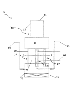
FIG. 1 presents a plan view of an embodiment of the dewatering or thickening
device
5. FIG. 2 presents a cross-section view of the device along section line 2-2
of FIG. 1. An
upper portion or head portion 10 is the upper portion of the device in which
sludge is allowed
to settle with free-water being removed from the sludge via the drainage space
90 provided
between the textile membrane 50 and the sludge at the anode 40 and/or cathode
30. The
sludge or pretreated biosolids enters through an inlet 11 and flows along a
conduit or pipe 12.
A lower portion or separation portion 20 is the lower portion of the device 5
in which
the thicker sludge settles. Free-water is removed in this portion of the
device simply by
CA 03006295 2018-05-24
WO 2017/091587
PCT/US2016/063356
-8-
allowing separated water to pass through the filter material around the anode
and cathode,
however the main mechanism of water removal in this stage of the device as
progressively
more water is removed is electro-osmotic flow into the space 90 between the
textile
membrane 50 and the sludge at the cathode 30 or anode 40.
In the embodiment shown, a cathode 30 may be an electrode composed of a
graphite
'sleeve' inserted in and affixed to the outer wall 25 of the device. In some
embodiments, the
outer wall 25 is made of a non-conductive material. For example, in some
embodiments, the
outer wall 25 is comprised of PVC pipe or similar material. The pipe 25 may be
connected to
the cathode 30 with an epoxy or similar material 28. While the embodiment
shown in FIGS.
1-2 show the cathode along the outer wall, in alternative embodiments the
anode may be
placed along the outer wall instead. An anode 40 may be similarly comprised of
a graphite
rod and positioned in the center of the lower portion according to the
embodiment shown in
FIGS. 1-2, but may be positioned elsewhere, alternatively. While the material
used for the
embodiment shown is graphite, different suitable materials, including a
conductive carbon-
fiber graphite impregnated rod or pipe may be used for the electrodes. The use
of a PVC
'sleeve' around the second, graphite electrode not only provides strength to
the cathode to
prevent it from deforming under pressure, but also provides the advantage of
being a low cost
material with excellent conductive properties.
In some embodiments, anode 40 is the inner electrode, and cathode 30 is the
outer
electrode. A filter material 50 (textile membrane) is wrapped inside the
cathode 30, and/or
around the outside of the anode 40. A filtrate drain space 90 between the
filter material 50
and the anode 40 or cathode 30 is provided to allow water to pass from the
sludge into this
interstitial space 90. The drain space 90 may be formed from a plastic,
textile or similar
mesh type material to provide structural support to the passageway without
interfering with
the flow of filtrate. The cathode 30, filter material 50, and filtrate drain
space 90 together
form a cathode compartment 27. The anode 40, filter material 50, and filtrate
drain space 90
together form an anode compartment 29. In some embodiments, the cathode 30 is
distal to
the filter material. A connection 60 to a DC power supply (continuous or
pulsed) provides
power to the anode 40 and cathode 30.
The space between the cathode compartment 27 and anode compartment 29 forms a
biosolids passageway 95. An outfall or outlet 70 of the device 5 is at the
bottom, and may
include an adjustable valve 75 if the device 5 is to be used as a thickening
device, or a simple
opening if the device is to be used for dewatering, in which case the sludge
cake provides a
"plug," preventing non-dewatered or non-thickened sludge from passing freely
through the
CA 03006295 2018-05-24
=
W02017/091587 PCT/US2016/063356
-9-
device 5. When operating to dewater, the valve 75, may be a simple 'flap' or
similarly-
functioning structure, may remain closed at the beginning of operation. Once
the biosolids
thicken to a desired degree of dewatering, the valve 75, or flap may be opened
and the system
may operate continuously to produce dewatered biosolids as the dewatered
"plug" moves
through the system, driven by the pressure from additional feed, above.
Filtrate outlets 80 are fluidly connected to the drain spaces 90 from the
anode and
cathode compartments 27 and 29. The drains are routed to the level of the
upper portion 20
of the device to allow filtrate to remain in the interstitial space 90, thus
provide conductivity
between the anode 30 and cathode 40 through the sludge.
In operation in the present system and process, chlorine dioxide may function
as a
flocculant. The resulting biosolids liquid exhibits a substantial increase in
settlability and
forms very small floc which allows water to pass freely through a filter
material or textile
membrane while retaining solids. The chlorine dioxide also modifies the
conductivity of the
biosolids to facilitate electro-osmotic flow. Electro-osmosis is the primary
factor in
electrokinetic dewatering and occurs when an electric field is applied to a
sludge segment via
electrodes. The net charge in the electrical double layer is induced to move
by the resulting
Coulomb force. The resulting flow is termed electro-osmotic flow, and is
defined by the
following formula:
dV e 4-
_____________________________ - _______
dt
Where:
V: water volume (m3)
t; time (s)
co: dielectric permittivity of vacuum (8.854X10⁻¹² CV- lm-1)
Er: dielectric constant of the liquid
zeta potential of sludge (V)
E: electrical field strength across the plug (Voi-1)
A: cross-sectional area (m2)
It viscosity of the liquid (kgm- Is-1)
The addition of chlorine dioxide increases the dielectric constant of the
liquid, may
increase the zeta potential of the sludge. Chlorine dioxide addition also
reduces the sludge
CA 03006295 2018-05-24
=
W02017/091587
PCT/US2016/063356
-10-
viscosity. These factors resulting from the addition of a single chemical
additive result in a
significant increase in the electro-osmotic flow.
Chlorine dioxide may be generated on-site to be used as a disinfectant for
municipal
sludge. Upon exposure to sufficient levels of chlorine dioxide for a
sufficient period of time,
the gross levels of bacteria in the wastewater biosolids stream are reduced to
allowable levels
for land application as Class B biosolids, with fecal coliform concentrations
below 2x10⁶
CPU or MPN/gram dry weight solids.
After being treated with chloride dioxide, in the present system and process,
the
pretreated liquid biosolids are introduced to a device that allows for a
current to be passed
through the biosolids. The device provides for current to pass from an anode
to a cathode
using the filtrate as a means of conductance between the electrodes and the
sludge to be
dewatered. This method prevents the sludge at the anode from becoming dry,
reducing the
electrical contact and causing an increase in resistance.
The primary obstacles to utilizing electrokinetic dewatering for municipal
sludge are
the time/space required for the operation as a batch process, the low
conductivity of
municipal sludge (which requires increased current to effect dewatering) and
the relatively
low throughput of existing electrokinetic dewatering processes. The methods
and devices
currently disclosed overcome these obstacles. The use of chlorine dioxide
improves the
conductivity and facilitates electro-osmosis, reducing the energy required to
operate the
process. The separation and removal of free water from the partially flocked
biosolids, while
using the filtrate as a means of conductance between the anode and cathode,
markedly
improves the efficiency of the process.
Continuous operation of the process allows for controlling the degree of water
removal by varying the rate of solids discharge from the device. This is
accomplished
without the complexity of other mechanical dewatering devices, such as a belt
filter-press.
Chlorine dioxide alone, when added to municipal sludge to produce biosolids,
results
in an increase in flocculation. This increase in flocculation is substantial
enough to allow for
mild floc to form in the biosolids, allowing for the release of free water
under controlled
conditions. The mechanical design provides these conditions and allows for the
removal of
free water without the addition of polymer, while at the same time providing a
means of
conductance between the anode and cathode.
The addition of pressure, even as low as 2.5 kPa, provides an increase in the
volume
of biosolids that can be processed by the system due to increased volume of
water removed
from the partially flocked sludge and the improved field strength. A small
amount of pressure
CA 03006295 2018-05-24
= WO 2017/091587
PCT/US2016/063356
-11-
applied to the system results in a higher current density and therefore more
efficient
operation.
The mechanical design includes a method of securing a conductive material,
such as
graphite to a circular supporting surface (pipe) in a manner that allow for
the pressurization
of the device without deformation of the graphite material (cracking). In this
manner,
graphite can be used as both the anode and cathode, increasing the efficiency
of the unit.
Since the zeta potential of untreated sludge is usually negative, the
direction of
electro-osmotic flow is from the anode to the cathode (sludge particles move
towards the
anode). As the electro-osmotic flow moves from the anode to the cathode a
moisture gradient
increases inside the filter cake. Thus, large unsaturated pores appear at the
anode side while a
compact moist cake is formed at the cathode. The negative charge at the
cathode repels
negatively charged sludge particles, preventing clogging of the filter
material and allowing
for the more rapid removal of filtrate especially in the upper portion of the
device where the
cake density is lower. Chlorine dioxide pre-treatment, however, imparts a
neutral or slightly
positive zeta potential to the sludge. This allows for more equal flow in both
directions,
substantially increasing the speed at which the material dewaters.
Electrical conductivity has an effect on electrokinetic dewatering
performance. Low
conductivity (e.g., a single digit conductivity measurement) is usually noted
in secondary
municipal sludges. The addition of chlorine dioxide can increase the
electrical conductivity
of waste activated sludge. Testing at a chlorine dioxide dose rate of 75 mg/L
results in
conductivity of 490 uS cm-i. If the conductivity is too high, this can cause a
reduction of the
electrical double layer of the particles and the zeta potential of particles,
and therefore a
reduction of electro-osmosis. This negative effect, however, has been noted to
occur usually
at conductivities above that produced through the addition of chlorine dioxide
to the
biosolids. The function and advantages of these and other embodiments will be
more fully
understood from the following non-limiting example. The example is intended to
be
illustrative in nature and is not to be considered as limiting the scope of
the embodiments
discussed herein.
EXAMPLE
To determine the effectiveness of the above-described process, an experimental
apparatus was arranged to quantify the removal rate of filtrate from a source
of pretreated
CA 03006295 2018-05-24
=
WO 2017/091587
PCT/US2016/063356
-12-
biosolids. A two-foot long device was created as depicted in Figures 1 and 2.
The first
(inner) electrode was constructed of a graphite rod. The second electrode was
a 6" diameter
graphite pipe. The first electrode was wrapped in a woven plastic mesh, then
enclosed in a
textile membrane to allow water to pass from the sludge, through the filtrate,
and to the
anode. The second electrode was placed inside a 24" section of PVC pipe, and
epoxied into
place. Woven plastic mesh material was wrapped inside the second electrode to
form a drain
space for filtrate to collect, and a textile membrane was wrapped inside the
textile membrane.
Secondary biosolids treated with chlorine dioxide were added to the upper
section of the
device, and a voltage of 24 V and a current of 3 A were applied to the device
from a power
source. The current used in testing was continuous, but may be pulsed. The
upper portion of
the device was a three-foot long clear PVC pipe to allow sludge to settle and
floc to form
prior to introduction into the lower portion of the device containing the
filter material and
electrodes. The upper portion had a diameter of four inches. The lower portion
had a
diameter of six inches.
The pretreated biosolids feed comprised 75 ppm chlorine dioxide and had a
total
solids composition of 0.5% to 1.2%. The head pressure from the upper portion
was
approximately 1.3 psi ¨2.17 psi., depending on the height to which the column
was filled. A
filtrate removal rate of 0.23 gallons per minute (gpm), or 360 gallons per day
(gpd), was
observed. Table 1, shows the rate of thickening of the mixture, beginning with
a solids
fraction of 1% at start and achieving 6.48% solids after six minutes.
TABLE 1
Minutes % Total Solids
0 1.00
1 1.16
2 1.39
3 1.73
4 2.29
3.39
6 6.48
Table 1 shows that the disclosed device is capable of achieving thickened
biosolids.
PROPHETIC EXAMPLE
CA 03006295 2018-05-24
WO 2017/091587
PCT/US2016/063356
-13-
The values obtained in the above-described Example were extrapolated to the
scale of
a full size water treatment plant, to determine the economic feasibility of
the process and
device. A filtrate removal rate of 0.23 gallons per minute (gpm) or 360
gallons per day (gpd)
was observed as described in the Example above. These numbers are scaled to
the typical
operation of a water treatment plant. For a flow rate of a million gallons per
day (mgd), a
plant (assuming a typical 2% waste rate) must waste about 13 gpm, or 18, 720
gpd. This
waste flow is generally about 1% total solids (ts). Therefore, to meet this
scale,
approximately 52 of the test two-foot devices would be required.
Alternatively, 10 ten-foot
tall devices could be used thicken to -6% (per mgd) prior to feed to an
anaerobic digester.
The footprint for ten devices would be approximately 18" x 36".
TABLE 2
Energy Calculator
Voltage Volts 24
Current Amps 3
Time hrs 24
Energy kWh 1.728
Energy Cost $/kWh $0.11
Total Energy Cost $ 0.19008
Total Cost $ 9.88
The operating cost of a two foot device is calculated in Table 2 to achieve
thickening
to about 6% biosolids. For the 24" test unit running 24 hrs/day, an electrical
cost of $0.19 is
incurred. $0.19 multiplied by 52 devices equals $9.88 per mgd for thickening,
which is
substantially less than typical polymer cost alone in a traditional method.
Assuming 10
lbs/dry ton for thickening, would be around $12/mgd in polymer costs.
This prophetic example demonstrates the economic feasibility of using the
disclosed
method and device scaled to the requirements of a water treatment plant.
The phraseology and terminology used herein is for the purpose of description
and
should not be regarded as limiting. As used herein, the term "plurality"
refers to two or more
items or components. The terms "comprising," "including," "carrying,"
"having,"
"containing," and "involving," whether in the written description or the
claims and the like,
CA 03006295 2018-05-24
= WO 2017/091587
PCT/US2016/063356
-14-
are open-ended terms, i.e., to mean "including but not limited to." Thus, the
use of such
terms is meant to encompass the items listed thereafter, and equivalents
thereof, as well as
additional items. Only the transitional phrases "consisting of" and
"consisting essentially of,"
are closed or semi-closed transitional phrases, respectively, with respect to
the claims. Use of
ordinal terms such as "first," "second," "third," and the like in the claims
to modify a claim
element does not by itself connote any priority, precedence, or order of one
claim element
over another or the temporal order in which acts of a method are performed,
but are used
merely as labels to distinguish one claim element having a certain name from
another element
having a same name (but for use of the ordinal term) to distinguish the claim
elements.
Having thus described several aspects of at least one embodiment, it is to be
appreciated various alterations, modifications, and improvements will readily
occur to those
skilled in the art. Any feature described in any embodiment may be included in
or substituted
for any feature of any other embodiment. Such alterations, modifications, and
improvements
are intended to be part of this disclosure, and are intended to be within the
scope of the
invention. Accordingly, the foregoing description and drawings are by way of
example only.