Note: Descriptions are shown in the official language in which they were submitted.
CA 03006422 2018-05-25
WO 2017/089834 PCT/GB2016/053730
1
AUTONOMOUS DOWNHOLE FLOW CONTROL VALVE FOR WELL PRESSURE CONTROL
FIELD
The present disclosure relates to a flow control device, particularly a
downhole
flow control device and a method of controlling a flow control device.
BACKGROUND
Oil and gas fields typically comprise a number of wells which are processed by
the same processing facility. The well conditions of each well may be
different, for
example, different wells may have different pressures. These differences can
be due
to, for example, penetrating different sections of the reservoir or different
reservoir
units. The variation in pressure can result in an imbalance of production
across the
wells.
Advanced completions or intelligent wells use valves or chokes in the
reservoir
that can be operated from the surface. These can be used to address or
minimise the
effect of imbalanced production across a formation.
Intelligent completion technology can be controlled from the surface using
multiple hydraulic and/or electric control lines which have to pass through
the wellhead
into the completion annulus and run along the entire production line to where
the
valves are located. There are limitations associated with the use of control
lines
including the high costs associated with the equipment, complexity and risk
during
deployment.
Wireless intelligent completions utilise electronic controlled interval
control
valves which include sensors and in well processors which enables remote
operation
and control of the completion by the operator from the surface. Wireless
telemetry, for
example pressure pulses, is used to send and receive signals from downhole
units to
the surface. The ability of the downhole control valve to react to changes in
the well
environment remains in the hands of the operator on the surface.
During hydraulic fracturing operations, adjacent and nearby wells have to be
isolated from the area being fractured. The wellhead is typically rated and
designed to
maintain a seal to isolate the well, however in practice a second barrier is
usually
provided to ensure pressure integrity. Two independent barriers for well
control is
normal practice and the second barrier is typically in the form of a
retrievable plug
installed downhole. After completion of the hydraulic fracturing operation,
the plug is
milled out. Any well within 0.5 to 1 mile of the fracking operation is
required to be
CA 03006422 2018-05-25
WO 2017/089834 PCT/GB2016/053730
2
protected in this manner and it may be required to carry out this operation 4
or 5 times
per well. The costs of plugging and milling can quickly build up during a
hydraulic
fracturing operation.
SUM MARY
According to an aspect of the present disclosure, there is provided a downhole
flow control device comprising:
a flow control valve;
a sensor in communication with the flow control valve, wherein the sensor
measures a local process parameter; and
wherein the flow control valve is configured to control the fluid flow through
the
valve to achieve a target local process parameter value in response to the
measured
local process parameter.
In use, the downhole flow control device provides a means for monitoring and
autonomously controlling the fluid production from a well. The flow control
device will
respond directly to changes in the downhole environment by changing the flow
path
through the valve as well conditions change without intervention from the
surface of the
well.
A local process parameter may be a process parameter measured in the vicinity
of the flow control device. For example, the sensor may measure the downhole
pressure at the location of the flow control device, and/or may measure the
pressure
drop across the flow control device, or measure the downhole pressure at the
location
of the flow control device.
The downhole flow control device may control the fluid flow through the flow
control valve independently from external instruction, wherein external
instruction
comprises, for example, communication from the surface of the well, and/or
input from
an operator.
The downhole flow control device may be autonomous.
The local process parameter may be, for example, the downstream pressure,
pressure drop across flow control valve, temperature, viscosity, or fluid
composition, for
example water content, measured in the vicinity of the flow control device
when located
downhole.
The target local process parameter value may be selected to maintain a surface
process parameter of the well at a desired value or within a desired range.
CA 03006422 2018-05-25
WO 2017/089834 PCT/GB2016/053730
3
The surface process parameter may be, for example, surface pressure or fluid
flow rate.
For example, the local process parameter may be pressure and the target local
process parameter value may be selected to maintain the surface pressure of
the well.
The target local process parameter value may be determined through nodal
analysis, for example nodal analysis may be performed on the well to determine
a
target process parameter value to produce a desired surface condition such as
well
head pressure.
The target local process parameter value may be programmed prior to
deployment of the flow control device downhole.
The target local process parameter value may be re-programmable whilst the
flow control device is in-situ. This increases the flexibility of the device
to adjust to
changing well conditions.
The target local process parameter value may be reprogrammed using
downhole wireless communication such as wireless telemetry. This allows the
flow
control device to be re-programmable without the need for removal of the
device from
the well.
The flow control device may comprise wireless communication technology such
as that described in W02006/041308 and/or W02006/041309. The flow control
device
may comprise a receiver and transmitter unit enabling it to be reconfigured
using
wireless telemetry.
Reconfiguring the flow control device may comprise a command to shutdown.
The local process parameter may be the same process parameter as the target
process parameter, or it may be a different process parameter. For example,
the target
process parameter may be flow rate and the local process parameter may be
pressure.
The flow control device may be configured to maintain the target downstream
pressure at a predetermined level to keep the surface pressure at or below a
predetermined level. The sensor may be selected to measure the local process
parameter, for example a pressure sensor or a temperature sensor. The sensor
may
be chosen to measure any local process parameter, for example, pressure,
temperature, flow rate, viscosity, fluid composition.
The flow control device may comprise a plurality of sensors configured to
measure different local process parameters, for example a pressure sensor and
temperature sensor.
CA 03006422 2018-05-25
WO 2017/089834 PCT/GB2016/053730
4
The flow control device may be re-configurable to respond to different process
parameters. For example, the flow control device may be configured to respond
to a
pressure reading from the sensor to achieve a target local pressure value, and
the flow
control device may be reconfigured to respond to a temperature reading and a
pressure reading from temperature and pressure sensors to achieve a target
downhole
flowrate.
The flow control valve may comprise a choke valve.
The valve may comprise an electro-mechanical actuator, for example a piston
or a sleeve.
The valve may be motor driven.
The valve may comprise a housing, wherein a piston is configured to extend
and retract into or out of the housing to alter the flow area of the valve.
The valve may comprise an infinitely variable choke actuator.
The size of the flow control valve may be selected based on computational
fluid
dynamics (CFD) analysis performed to determine the range of valve size
required to
achieve the target local process parameter value.
A range of valve size may be preferable over a fixed valve size to account for
declining reservoir pressure.
The flow control valve may further comprise a seal to facilitate the valve
maintaining a seal when in a closed position.
The flow control device may comprise an electronics module.
The electronics module may act as a controller for the flow control valve.
The electronics module may act as the controller for the sensor.
The sensor and flow control valve may be controlled by a shared electronics
module.
The electronics module may comprise an on-board processor.
The flow control device may use the target local process parameter value as a
reference in a closed loop control system.
In use, the sensor may measure the local process parameter at set intervals.
The processor may compare the measured local process parameter value with the
target local process parameter value to determine if the actual local process
parameter
needs to be adjusted; the flow control valve may then alter the fluid flow
through the
valve to achieve the target local process parameter value.
CA 03006422 2018-05-25
WO 2017/089834 PCT/GB2016/053730
The intervals may be selected depending on the process, for example
measurements may be taken in second intervals, minute intervals, hour
intervals, day
intervals or week intervals.
The sensor may be configured to continuously measure the local process
5 parameter as the flow control valve changes the fluid flow through the
valve to achieve
the target local process parameter value. The term "continuously" may comprise
taking
measurements at set intervals, where the intervals are short, for example
taking a
measurement every second, every five seconds, every 10 seconds. When the
target
local process parameter value has been reached, the flow control device may be
configured to instruct the flow control valve to hold its position.
The flow control device may be configured to remain open until production is
started. The flow control device may be located inside down hole tubing. This
may allow
for the flow control device to be retrievable.
The flow control device may be configured to form part of a downhole tubing
string.
The tubing may be production tubing.
The flow control device may be located at any location within the production
tubing, for example, the flow control device may be located to avoid hydrate
formation.
The flow control device may be located in the heel of the production tubing.
The flow control device may be an inflow control valve (ICV) for use in a
production well.
The flow control device may be an inflow control valve for use in isolating at
least a portion of the production well. For example, the flow control device
may be used
in hydraulic fracturing operations to isolate a distal portion of the well
while hydraulic
fracturing takes place in adjacent or nearby wells.
In use as an isolation valve, the target process parameter may be no fluid
flow,
or no fluid flow path or any process parameter associated with the flow valve
being
closed. The local process parameter may be, for example pressure or flow. The
flow
control valve may be configured such that when a pressure is detected within
an
accepted value or range, the flow control valve may close. The flow control
valve may
be configured such that when a flow rate of zero flow is detected, the flow
control valve
may close.
The flow control device may be configured to act as an isolation valve prior
to
running in hole.
CA 03006422 2018-05-25
WO 2017/089834 PCT/GB2016/053730
6
The flow control device may be reconfigured to act as an isolation valve
whilst
in-situ downhole.
The flow control device may be designed to withstand a pressure up to a
desired pressure value required to isolate the well, for example but not
limited to, 8,000
psi, 10,000 psi.
A production well may be shut-in, for example from the surface, to stop
production of the well. This may comprise closing a valve located at or near
the surface
of the production well. When a production well is shut-in, the downhole
pressure at or
near the flow control valve may increase.
The flow control device may be configured to detect when a shut-in of the well
has taken place.
The flow control device may be configured to remain open until a shut-in of
the
well is detected. This may allow fluid flow through the flow control device
during
production of the well.
The flow control device may be used during the production of the well as a
flow
control device to maintain a desired surface process parameter and may be
configured
to be reconfigured whilst in-situ to be used as an isolation valve. For
example the flow
control device may be reconfigured using wireless telemetry to change the
target
process parameter to close the valve in response to a shut-in. The flow
control device
may be configured to measure the local pressure at set intervals. The
intervals may be
selected depending on the process, for example measurements may be taken in
second intervals, minute intervals, hour intervals, day intervals or week
intervals.
In use as an isolation valve, when a well is shut-in, the flow control device
may
detect an elevated local pressure. For example, an elevated pressure reading
over a
minimum period of time may indicate that the well has been closed and the flow
control
device may reconfigure to achieve the target process parameter of no fluid
flow path
through the valve.
The flow control device may be configured to recognise an elevated pressure
value or increased pressure differential across the valve detected over a
minimum time
to be associated with a well shut-in. The minimum time may be, for example one
minute, five minutes, ten minutes, fifteen minutes, twenty minutes, one hour,
or any
appropriate time interval required by the flow control device.
The flow control device may reconfigure to a closed position in response to a
pressure indicating a shut-in of the well.
CA 03006422 2018-05-25
WO 2017/089834 PCT/GB2016/053730
7
When the target local process parameter value has been reached, the valve
may be closed and the flow control device may be configured to instruct the
flow valve
to hold this configuration.
In the closed position, the flow control device may maintain a seal and
isolate at
least a portion of the well, for example a distal portion of the well.
The flow control device may be configured to measure the local pressure whilst
the flow control device is closed, for example, the flow control device may
measure the
local pressure at set intervals, for example every minute, or every five
minutes, every
ten minutes, every hour or any suitable interval, or the flow control device
may be
configured to measure the local pressure continuously whilst the flow control
device is
closed. The term "continuously" may comprise taking measurements at set
intervals,
where the intervals are short, for example taking a measurement every second,
every
five seconds, every 10 seconds.
The flow control device may be configured to open when the wellhead is
opened, for example, after hydraulic fracturing operations have been
completed.
The flow control device may be configured to open when the local pressure
value above or below the valve corresponds to a value or within a pressure
range
associated with the well being open, or when a predetermined pressure
differential
across the valve is detected.
The flow control device may be configured to open or remain open when the
local pressure is outside of an accepted range or value associated with the
well being
shut-in or associated with hydraulic fracturing operations occurring in
adjacent or
nearby wells, or the flow control device may be configured to open when the
local
pressure is within an accepted range associated with the well being open or
hydraulic
fracturing operations being complete. For example, when the well is opened or
if
hydraulic fracturing operations in nearby wells are stopped, the local
pressure may
decrease and the flow control device may be configured to respond to this
pressure
decrease by opening the flow control valve. A reduction in pressure measured
over a
minimum period of time may indicate that the well has been opened and the flow
valve
may open allowing the well to resume production.
The flow control device may be configured to remain closed until the flow
control device is instructed to open, for example at such time as hydraulic
fracturing
operations in adjacent or nearby wells have been completed.
Instructing the flow control device to open may comprise sending a signal to
the
flow control device, for example using wireless telemetry. For example, a
pressure
CA 03006422 2018-05-25
WO 2017/089834 PCT/GB2016/053730
8
signal from the surface of the well may be sent to the flow control device
when the well
is opened following a shut-in, or in preparation for the well being opened
following a
shut-in. Upon receiving this pressure signal, the flow control device may
open.
The flow control device may be configurable between an active and a passive
configuration. In the passive configuration, the flow control device may
measure a local
process parameter, and compare the local process parameter to a target process
parameter to, for example, determine whether the actual local process
parameter
needs to be adjusted. In the active configuration, the flow control valve may
alter the
fluid flow through the valve to achieve the target local process parameter
value.
The flow control device may be configured to the active configuration during
well shut-in. Additionally, or alternatively, the flow control device may be
configured to
the active configuration during production and/or when the wellhead is opened.
The
flow control device may be configured to the passive configuration once the
target
process parameter has been reached.
In the passive configuration, the flow control valve may not require to be
altered. As such, in the passive configuration, the flow control device may
consume
less power than in the active configuration, thereby extending battery life,
for example.
The flow control device may be configured to reset following opening after a
shut-in such that the flow control device may remain open until another shut-
in is
detected.
The flow control device may be powered by a local power source.
The flow control device may be battery powered. The number of batteries may
be selected according to the desired lifetime of the flow control device, for
example one
battery, two batteries, three batteries, or four batteries. The number of
batteries may be
limited by the rig-up height and handling of the flow control device.
The flow control device may be powered by a downhole generator. For
example, the flow control device may be powered by a turbine for energy
extraction
from fluid flowing within a conduit, such as that described in UK patent
publication
number 2531025 and/or W02016/055451 and/or W02014118503.
According to a second aspect of the present disclosure, there is provided a
control system for a downhole flow control device comprising:
a closed loop control system wherein a flow control valve located downhole
adjusts to achieve a target local process parameter value in response to a
measured
local process parameter reading from a sensor in communication with the flow
control
valve.
CA 03006422 2018-05-25
WO 2017/089834 PCT/GB2016/053730
9
The control system may comprise a plurality of sensors in communication with
the flow control valve.
Each sensor may measure a different process parameter.
The target local process parameter value may be a reference in the closed loop
control system.
The control system may be configured such that the sensor measures the
downhole process parameter at set intervals. For example, the sensor may be
configured to take measurements in second intervals, minute intervals, day
intervals,
week intervals or month intervals.
The control system may be configured to continuously measure the local
process parameter as the flow valve adjusts the fluid flow through the valve
to achieve
the target local process parameter value. The term "continuously" may comprise
taking
measurements at set intervals, where the intervals are short, for example
taking a
measurement every second, every five seconds, every 10 seconds. When the
target
local process parameter value has been reached, the control system may be
configured to instruct the flow valve to hold its position. The control system
may be
configured to be reprogrammable when required by well conditions, for example
the
target downhole process parameter value may be changed, the downhole process
parameter may be changed, and the flow control valve may be shut down.
The control system may be reprogrammable whilst the downhole flow control
device is in-situ.
The control system may be reprogrammable using downhole wireless
telemetry, for example the wireless communication technology such as that
described
in W02006/041308 and/or W02006/041309.
The control system may be configured to set the flow control device to idle
whilst no flow is detected. The control system may comprise an outer loop and
an inner
loop.
The outer loop may detect if the well is flowing and whether or not any
communication is due to be received or sent from the flow control device. When
flow is
detected, the control system may move to the inner loop.
The inner control loop may determine if the measured downhole process
parameter is within an accepted tolerance for the target local process
parameter value
and may adjust the flow valve accordingly. If the measured downhole process
parameter is within the accepted tolerance for the target process parameter,
the control
system may move back to the outer loop.
CA 03006422 2018-05-25
WO 2017/089834 PCT/GB2016/053730
The outer loop may measure a local downhole process parameter to determine
whether the well has been shut-in at or near the surface. For example, an
elevated
local pressure over a minimum time may signal that the well has been shut-in.
When a
shut-in is detected, the control system may move to the inner loop. If no shut-
in is
5 detected, the outer control loop may take local downhole process
parameters at set
intervals.
The inner control loop may have a target local process parameter of no fluid
flow, or no fluid flow path, or any process parameter associated with the flow
control
valve being closed. When the control system moves to the inner control loop,
the
10 control system may reconfigure the flow valve to achieve the target
process parameter,
for example the flow control valve will close.
The inner loop may measure the downhole process parameter at set intervals
and whilst the downhole process parameter is within an accepted range,
instruct the
flow control valve to remain closed. If the downhole process parameter is not
within the
accepted range, the inner loop may instruct the flow valve to open and the
control
system may return to the outer loop.
For example, the downhole process parameter may be pressure. The inner loop
may determine if the measured pressure or pressure differential across the
flow control
valve is within an accepted range for the flow valve to remain closed. The
inner loop
may determine if the measured pressure or pressure differential across the
valve is
within an accepted range for the flow valve to open. The accepted range may be
a
pressure or pressure range associated with the well being shut in or a
pressure range
associated with hydraulic fracturing operations taking place in adjacent or
nearby wells,
or the accepted range may be a pressure value or range associated with the
wellhead
being open, or associated with hydraulic fracturing operations being
completed. If the
inner loop determines the detected pressure value is below the accepted range
or
within the accepted range, the inner loop may instruct the flow control valve
to open.
For example, a decrease in local pressure to a pressure below the accepted
range or
within the accepted range, or a decrease in differential pressure across the
valve may
indicate that the wellhead has been opened and the flow valve can be opened.
The control system may be operable to set the flow control valve between the
active configuration and the passive configuration. When the flow control
valve is in the
active configuration, the control system may operate using the inner loop.
When the
flow control valve is in the passive configuration, the control system may
operate using
the outer loop.
CA 03006422 2018-05-25
WO 2017/089834 PCT/GB2016/053730
11
The control system may be configured to receive a communication from surface
to open the flow valve. For example, a communication sent from the surface
using
wireless telemetry. The communication may be in the form of a pressure signal.
Upon
receipt of the communication, the control system may instruct the flow vale to
open and
the control system may return to the outer control loop.
Features described in relation to the flow control device of the first aspect
apply
mutatis mutandis to the second aspect.
According to a third aspect of the present disclosure, there is provided a
method of controlling a downhole flow control device comprising:
programming a downhole flow control device with a target local process
parameter value;
locating the downhole flow control device downhole, wherein the device
comprises a flow control valve and a sensor in communication with the flow
valve;
measuring a local process parameter with the sensor;
wherein the flow valve controls the fluid flow through the valve to achieve
the
target local process parameter in response to the measured local process
parameter.
The method may be used to control fluid production from a well.
The method may comprise locating the downhole flow control device in
production tubing, wherein the downhole flow device may form part of the
tubing or be
located inside the tubing.
The method may comprise a closed loop control system wherein the target local
process parameter value is a reference.
The method may comprise reconfiguring the flow control device if necessary
according to well conditions, for example the target downhole process
parameter value
may be changed, the downhole process parameter may be changed, and the flow
control valve may be shut down.
The method may comprise reconfiguring the flow control device whilst the flow
control device is in situ.
The method may comprise reconfiguring the flow control device using downhole
wireless communication such as wireless telemetry, for example the wireless
communication technology such as that described in W02006/041308 and/or
W02006/041309.
The method may comprise operating the flow control valve during production of
the well, for example where the target process parameter is selected to obtain
a
predetermined rate of production of the well. The target process parameter may
be, for
CA 03006422 2018-05-25
WO 2017/089834 PCT/GB2016/053730
12
example pressure, temperature, flow rate and viscosity. The local process
parameter
detected by the sensor may be, for example pressure, temperature, flow rate
and
viscosity. The local process parameter may be the same or different from the
target
process parameter.
The method may comprise operating the flow control valve as an isolation
valve. In use as an isolation valve, the target process parameter may be no
fluid flow,
or no fluid flow path or any process parameter associated with the flow
control valve
being closed. The local process parameter may be pressure and the flow control
valve
may be configured such that when a pressure is detected within an accepted
value or
range, the flow control valve may close.
The method may comprise configuring the flow control device to operate as an
isolation valve prior to running in hole.
The method may comprise configuring the flow control device to operate as an
isolation valve whilst in-situ downhole.
The method may comprise isolating a portion of a well, for example a distal
portion of the well.
The flow control device may be used to isolate a portion of the well during
hydraulic fracturing operations to isolate a portion of the well while
adjacent or nearby
wells are being fractured.
The method may comprise detecting when the well has been shut-in. For
example, the local process parameter may be pressure and the method may
comprise
the sensor measuring the downhole pressure. The method may comprise measuring
the local pressure at set intervals. The intervals may be selected depending
on the
process, for example measurements may be taken in second intervals, minute
intervals, hour intervals, day intervals or week intervals. An elevated
pressure detected
over a minimum period of time may indicate that the well has been closed and
the flow
valve may adjust to achieve the target process parameter of no fluid flow,
wherein the
fluid flow valve will close.
The method may comprise reconfiguring the flow control valve to a closed
position to achieve the target local process parameter of zero flow, or zero
fluid flow
path in response to a pressure indicating a shut-in of the well.
The method may comprise maintaining the flow control valve in the closed
position to isolate and seal a portion of the production well. The flow
control valve may
be designed to withstand a required pressure to isolate the well, for example
but not
limited to 8,000 psi or 10,000 psi.
CA 03006422 2018-05-25
WO 2017/089834 PCT/GB2016/053730
13
The method may comprise opening the valve, for example when the well is
opened. For example when a valve at the wellhead has been opened.
The method may comprise detecting when the well has been opened.
The method may comprise detecting if the measured local pressure or pressure
differential is within an accepted range for the flow control valve to remain
closed. The
accepted range may be a pressure range associated with the well being shut in
from
surface or a pressure range associated with hydraulic fracturing operations
taking
place in adjacent wells. For example, when a well is shut-in, the pressure at
or near the
flow control valve may increase.
The method may comprise detecting if the measured local pressure or pressure
differential across the valve is within an accepted range for the flow valve
to open. The
accepted range may be a reduced pressure range or pressure differential
associated
with the wellhead being open, or associated with hydraulic fracturing
operations being
completed.
The method may comprise determining if the measured pressure value is below
the accepted range or within the accepted range and opening the flow control
valve
open. For example, a decrease in local pressure to a pressure below the
accepted
range or to within the accepted range may indicate that the wellhead has been
opened
and the flow valve can be opened.
The method may comprise sending a signal, for example a wireless
communication to the flow control device to open the valve. For example, a
pressure
pulse sent from the surface may trigger the flow control valve to reopen.
The method may comprise operating the flow control valve during production of
the well and reprogramming the flow control valve in-situ to operate as an
isolation
valve. The method may comprise operating the flow control valve as an
isolation valve
and reconfiguring the flow valve in-situ to operate during production of the
well.
Features described in relation to the flow control device of the first aspect
and
the control system of the second aspect apply mutatis mutandis to the method
of the
third aspect.
According to a fourth aspect of the present disclosure, there is provided a
downhole flow control device for isolating a portion of a well, the flow
control device
comprising:
a flow control valve;
a sensor in communication with the flow control valve, wherein the sensor
measures a local process parameter; and
CA 03006422 2018-05-25
WO 2017/089834 PCT/GB2016/053730
14
wherein the flow control valve is configured to close in response to the
measured local process parameter.
In use, the downhole flow control device provides a means to isolate a portion
of a well independently from external instruction, wherein external
instruction
comprises, for example, communication from the surface of the well, and/or
input from
an operator.
The flow control device may be autonomous.
The flow control device may be configured to isolate a portion of the well,
for
example a distal portion of the well during hydraulic fracturing operations on
adjacent
or nearby wells.
A local process parameter may be a process parameter measured in the vicinity
of the flow control device. For example, the sensor may detect the downhole
pressure
at the location of the flow control device, and/or may measure the pressure
drop across
the fluid control device, or measure the downhole pressure at the location of
the flow
control device.
The local process parameter may be, for example, the downstream pressure or
pressure drop across flow control valve measured in the vicinity of the flow
control
device when located downhole.
The flow control device may be located inside downhole tubing. This may allow
for the flow control device to be retrievable.
The flow control device may be configured to form part of a downhole tubing
string.
The tubing may be production tubing.
The flow control device may be located at any location within the production
tubing, for example the flow control device may be located in the production
tubing
above the hydrocarbon bearing formation such that a distal portion of the well
is
isolated when the flow control valve is closed.
The flow control device may be an inflow control valve for use in isolating a
portion of a production well. For example, the flow control device may be used
to
isolate a portion of the well while hydraulic fracturing takes place in
adjacent or nearby
wells.
In use as an isolation valve, the local process parameter may be, for example
pressure or flow. The flow control valve may be configured such that when a
pressure
is detected within an accepted value or range, the flow control valve may
close. The
CA 03006422 2018-05-25
WO 2017/089834 PCT/GB2016/053730
flow control valve may be configured such that when a flow rate of zero flow
is
detected, the flow control valve may close.
The flow control device may be configured to act as an isolation valve prior
to
running in hole.
5 The
flow control device may be reconfigured to act as an isolation valve whilst
in-situ downhole.
The flow control device may be designed to withstand a pressure up to a
desired pressure value required to isolate the well, for example but not
limited to, 8,000
psi, 10,000 psi.
10 A
production well may be shut-in, for example from the surface, to stop
production of the well. This may comprise closing a valve located at or near
the surface
of the production well. When a production well is shut-in, the downhole
pressure may
increase and fluid flow will be zero.
The flow control device may be configured to detect when a shut-in of the well
15 has taken place.
The flow control device may be configured to remain open until a shut-in of
the
well is detected. This may allow fluid flow through the flow control device
during
production of the well.
The flow control device may be used during the production of the well as a
flow
control device to maintain a desired surface process parameter and may be
configured
to be reconfigured whilst in-situ to be used as an isolation valve. For
example the flow
control device may be reconfigured using wireless telemetry to change the
target
process parameter to achieve a closed valve in response to a shut-in. The flow
control
device may be configured to measure the local pressure at set intervals. The
intervals
may be selected depending on the process, for example measurements may be
taken
in second intervals, minute intervals, hour intervals, day intervals or week
intervals.
In use as an isolation valve, when a well is shut-in, the flow control device
may
detect an elevated local pressure. For example, an elevated pressure reading
over a
minimum period of time may indicate that the well has been closed and the flow
control
device may reconfigure to achieve the target process parameter of no fluid
flow path
through the valve.
The flow control device may be configured to recognise a pressure value or
pressure differential across the valve detected over a minimum time to be
associated
with a well shut-in. The minimum time may be, for example one minute, five
minutes,
CA 03006422 2018-05-25
WO 2017/089834 PCT/GB2016/053730
16
ten minutes, fifteen minutes, twenty minutes, one hour, or any appropriate
time interval
required by the flow control device.
The flow control device may reconfigure to a closed position in response to a
pressure indicating a shut-in of the well.
The flow control device may be configured to instruct the flow valve to hold
this
configuration.
In the closed position, the flow control device may maintain a seal and
isolate at
least a portion of the well, for example a distal portion of the well.
The flow control device may be configured to measure the local pressure whilst
the flow control device is closed, for example, the flow control device may
measure the
local pressure at set intervals, for example every minute, or every five
minutes, every
ten minutes, every hour or any suitable interval, or the flow control device
may be
configured to measure the local pressure continuously whilst the flow control
device is
closed. The term "continuously" may comprise taking measurements at set
intervals,
where the intervals are short, for example taking a measurement every second,
every
five seconds, every 10 seconds.
The flow control device may be configured to open when the wellhead is
opened, for example, after hydraulic fracturing operations have been
completed.
The flow control device may be configured to open when the local pressure
value above or below the valve corresponds to a value or within a pressure
range
associated with the well being open, or when a predetermined pressure
differential
across the valve is detected.
The flow control device may be configured to open or remain open when the
local pressure is outside of an accepted range or value associated with the
well being
shut-in or associated with hydraulic fracturing operations occurring in
adjacent or
nearby wells, or the flow control device may be configured to open when the
local
pressure is within an accepted range associated with the well being open or
hydraulic
fracturing operations being complete. For example, when the well is opened or
if
hydraulic fracturing operations in nearby wells are stopped, the local
pressure may
decrease and the flow control device may be configured to respond to this
pressure
decrease by opening the flow control valve. A reduction in pressure measured
over a
minimum period of time may indicate that the well has been opened and the flow
valve
may open allowing the well to resume production.
CA 03006422 2018-05-25
WO 2017/089834 PCT/GB2016/053730
17
The flow control device may be configured to remain closed until the flow
control device is instructed to open, for example at such time as hydraulic
fracturing
operations in adjacent or nearby wells have been completed.
Instructing the flow control device to open may comprise sending a signal to
the
flow control device, for example using wireless telemetry. For example, a
pressure
signal from the surface of the well may be sent to the flow control device
when the well
is opened following a shut-in, or in preparation for the well being opened
following a
shut-in. Upon receiving this pressure signal, the flow control device may
open.
The flow control device may be configured to reset following opening after a
shut-in such that the flow control device may remain open until another shut-
in is
detected.
The flow control device may be reconfigured for use during production of the
well. For example, the flow control device may be reconfigured to have a
target local
process parameter which is selected to maintain a desired surface process
parameter.
The flow control device may reconfigure the fluid flow path to achieve the
target local
process parameter is response to the measured local process parameter. The
measured local process parameter may be re-programmed whilst the flow valve is
in-
situ.
The target local process parameter value and the local process parameter may
be reconfigured using downhole wireless communication such as wireless
telemetry.
This allows the flow control device to be re-configurable without the need for
removal of
the device from the well.
The flow control device may comprise wireless communication technology such
as that described in W02006/041308 and/or W02006/041309. The flow control
device
may comprise a receiver and transmitter unit enabling it to be reprogrammed
using
wireless telemetry.
The flow control valve may comprise a choke valve.
The valve may comprise an electro-mechanical actuator, for example a piston
or a sleeve.
The valve may be motor driven.
The valve may comprise a housing, wherein a piston is configured to extend
and retract into or out of the housing to alter the flow area of the choke
valve.
The valve may comprise an infinitely variable choke actuator.
CA 03006422 2018-05-25
WO 2017/089834 PCT/GB2016/053730
18
The size of the flow control valve may be selected based on computational
fluid
dynamics (CFD) analysis performed to determine the range of valve size
required to
achieve the target local process parameter value.
A range of valve size may be preferable over a fixed valve size to account for
declining reservoir pressure.
The flow control valve may further comprise a seal to facilitate the valve
maintaining a seal when in a closed position.
The flow control device may comprise an electronics module.
The electronics module may act as a controller for the flow control valve.
The electronics module may act as the controller for the sensor.
The sensor and flow control valve may be controlled by a shared electronics
module.
The electronics module may comprise an on-board processor.
The flow control device may be powered by a local power source.
The flow control device may be battery powered. The number of batteries may
be selected according to the desired lifetime of the flow control device, for
example one
battery, two batteries, three batteries, or four batteries. The number of
batteries may be
limited by the rig-up height and handling of the flow control device.
The flow control device may be powered by a downhole generator. For
example, the flow control device may be powered by a turbine for energy
extraction
from fluid flowing within a conduit, such as that described in UK patent
publication
number 2531025 and/or W02016/055451 and/or W02014118503.
Features described in relation to other aspects of the present disclosure
apply
mutatis mutandis to the flow control vale of the fourth aspect.
According to another aspect of the present disclosure, there is provided a
method of isolating a portion of a well during hydraulic fracturing
operations, the
method comprising
locating a flow control valve downhole,
closing the well;
closing flow control valve; and
performing hydraulic fracturing operations on an adjacent or nearby well.
The method may further comprise measuring a downhole process parameter
with a sensor in communication with the flow control valve, wherein the flow
control
valve will close in response to the measured downhole process parameter.
CA 03006422 2018-05-25
WO 2017/089834 PCT/GB2016/053730
19
The flow control valve may close without intervention from the surface of the
well.
The downhole process parameter may be, for example pressure or flow.
The method may comprise detecting a pressure within an accepted value or
range and closing the flow control valve.
The method may comprise detecting no fluid flow and closing the flow control
valve.
The method may further comprise closing the well at or near the surface, for
example by closing a valve located at or near the surface of the well.
The method may comprise detecting when a shut-in of the well has taken place.
The method may comprise configuring the flow control valve to remain open
until a shut-in of the well is detected.
The method may further comprise producing through the valve. The method
may further comprise producing when the valve is in an open or partially open
configuration. The method may comprise configuring the flow control valve to
maintain
a desired surface process parameter, for example a pre-determined flow rate or
pressure.
The method may comprise detecting an elevated local pressure and closing the
flow control valve. For example, an elevated pressure reading over a minimum
period
of time may indicate that the well has been closed and the flow control device
may
close.
The method may comprise recognising a pressure value or pressure differential
across the valve detected over a minimum time to be associated with a well
shut-in.
The minimum time may be, for example one minute, five minutes, ten minutes,
fifteen
minutes, twenty minutes, one hour, or any appropriate time interval required
by the flow
control device.
The method may comprise maintaining the flow control valve in the closed
configuration. In the closed configuration, the flow control valve may
maintain a seal
and isolate at least a portion of the well, for example a distal portion of
the well.
The method may comprise detecting the local pressure whilst the flow control
valve is closed, for example, the flow control device may detect the local
pressure at
set intervals, for example every minute, or every five minutes, every ten
minutes, every
hour or any suitable interval, or the flow control valve may be configured to
detect the
local pressure continuously whilst the flow control valve is closed. The term
"continuously" may comprise taking measurements at set intervals, where the
intervals
CA 03006422 2018-05-25
WO 2017/089834 PCT/GB2016/053730
are short, for example taking a measurement every second, every five seconds,
every
10 seconds.
The method may further comprise opening the flow control valve. For example,
the method may comprise opening the flow control valve after hydraulic
fracturing
5 operations on the adjacent or nearby well have been completed.
The method may comprise opening the flow control valve when the local
pressure value above or below the valve corresponds to a value or within a
pressure
range associated with the well being open, or when a predetermined pressure
differential across the valve is detected.
10 The method may comprise opening or holding the flow control valve open
when
the local pressure is outside of an accepted range or value associated with
the well
being shut-in or associated with hydraulic fracturing operations occurring in
adjacent or
nearby wells, or opening or holding the flow control valve open when the local
pressure
is within an accepted range associated with the well being open or hydraulic
fracturing
15 operations being complete. For example, when the well is opened or if
hydraulic
fracturing operations in nearby wells are stopped, the local pressure may
decrease and
the flow control valve may be configured to respond to this pressure decrease
by
opening the flow control valve. A reduction in pressure measured over a
minimum
period of time may indicate that the well has been opened and the flow valve
may open
20 allowing the well to resume production.
The method may comprise maintaining the flow control valve in the closed
configuration until the flow control device is instructed to open, for example
at such
time as hydraulic fracturing operations in adjacent or nearby wells have been
completed.
The method may further comprise instructing the flow valve to open.
Instructing
the flow control valve to open may comprise sending a signal to the flow
control valve,
for example using wireless telemetry. For example, a pressure signal from the
surface
of the well may be sent to the flow control valve when the well is opened
following a
shut-in, or in preparation for the well being opened following a shut-in. Upon
receiving
this pressure signal, the flow control device may open.
The method may further comprise reconfiguring the flow control valve to
maintain a pre-determined production rate from the well. For example the flow
control
device may be reconfigured using wireless telemetry.
The method may comprise configuring the flow control valve between the active
and passive configuration.
21
The method may comprise configuring the flow control valve to the active
configuration during well shut-in.
According to another aspect of the present disclosure, there is provided a
downhole flow control and isolation device for use in a production well,
comprising: a
flow control valve locatable within the well at a downhole location, wherein
the flow
control valve is controlled by a processor, the processor being configured to
recognize a
shut-in event; a sensor in communication with the flow control valve, wherein
the sensor
is configured to measure a local process parameter within the well, the sensor
being
controlled by the processor; wherein the flow control valve is configurable by
the
processor in a flow control configuration in which flow control is adjusted
between fully
open, partially open and fully closed positions via an infinitely variable
choke actuator, in
response to the measured local process parameter to control a fluid flow
through the
valve during production from the well to achieve a target local process
parameter; and
wherein the flow control valve is reconfigurable by the processor to an
isolation
configuration in which the flow control valve is closed to reduce flow
therethrough and
isolate a portion of the well at the downhole location, the flow control valve
being
reconfigurable to its isolation configuration in response to the measured
local process
parameter being indicative of the well being shut-in, as recognized by the
processor.
According to another aspect of the present disclosure, there is provided a
method
of operating a downhole flow control and isolating device in a production
well, the method
comprising: locating the downhole flow control and isolating device within the
well at a
downhole location, wherein the device comprises a flow control valve and a
sensor in
communication with the flow valve; operating the flow control valve in a flow
control
configuration in which the flow control valve is adjusted between fully open,
partially open
and fully closed positions via an infinitely variable choke actuator, in
response to a
measured local process parameter to control a fluid flow through the valve
during
production from the well to achieve a target local process parameter value;
detecting that
the measured local process parameter indicates that the well has been shut-in;
and
operating the flow control valve in an isolation configuration in which the
flow control
valve is closed to reduce flow therethrough to isolate a portion of the well
at the downhole
location.
According to another aspect of the present disclosure, there is provided a
method
of operating and isolating a well, the method comprising: locating a downhole
flow control
and isolation device within the well at a downhole location, wherein the
device comprises
a flow control valve and a sensor in communication with the flow control
valve; operating
the flow control valve in a flow control configuration in which the flow
control valve is
Date Recue/Date Received 2023-04-12
21a
adjusted between fully open, partially open and fully closed positions, via an
infinitely
variable choke actuator, in response to a measured local process parameter to
control a
fluid flow through the valve during production from the well to achieve a
target local
process parameter value; closing the well; detecting that the measured local
process
parameter indicates that the well has been shut-in; and operating the flow
control valve
in an isolation configuration in which the flow control valve is closed to
prevent flow
therethrough to isolate a portion of the well at the downhole location.
Features described in relation to other aspects of the present disclosure
apply mutatis mutandis to the method described in this aspect.
BRIEF DESCRIPTION OF THE DRAWINGS
These and other aspects of the present disclosure will now be described, by
way
of example only, with reference to the accompanying drawings, in which:
Figure la shows a schematic cut-away diagram of an in-line flow control device
according to the present disclosure;
Figure lb shows a schematic diagram of the flow control device shown in Figure
la;
Figure 2a shows a schematic cut-away diagram of an annular flow control device
according to the present disclosure;
Figure 2b shows a schematic diagram of the flow control device of Figure 2a;
Figure 3 shows a detailed schematic of the outer control and inner control
loop
for the fluid control device; and
Figure 4 shows a schematic of the flow control device of the present
disclosure
in use during a hydraulic fracturing operation.
DETAILED DESCRIPTION OF THE DRAWINGS
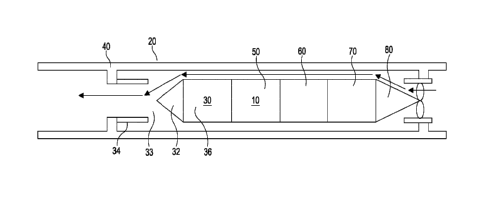
The downhole flow control device 10 in use is deployed within a wellbore which
intercepts a subterranean formation which contains hydrocarbons. In the
embodiment
shown in Figures la and lb, the flow control device 10 is deployed inside
production tubing
20, configured to communicate fluids, such as gas, produced from the formation
to the
surface. Alternatively, the flow control device can form part of the
production tubing, and
will be run as part of the completion, either directly attached to the tail
pipe or with the
completion itself, as shown in Figures 2a and 2b.
The flow control device 10 has a flow control valve 30 in the form of a choke
valve
with an infinitely variable choke system. Choke valve 30 has an electro-
mechanical
piston 32 and a choke housing 34. The position of the piston 32 with respect
to the choke
Date Recue/Date Received 2023-04-12
21b
housing forms a choke inlet 33. The valve 30 has a drive mechanism and motor
36 to
move the piston of the choke valve. The flow control device has a sensor
module 50
containing sensors to measure the desired process parameter. The skilled
person will
appreciate that the sensors may be chosen to
Date Recue/Date Received 2023-04-12
CA 03006422 2018-05-25
WO 2017/089834 PCT/GB2016/053730
22
measure any downhole process parameter, for example, pressure, temperature,
flow
rate, viscosity, fluid composition. The sensors 55 are in communication with a
sensor
module 50 in the flow control device 10. An on-board electronics processor
module 60
is present which controls both the sensors and the choke valve. The device 10
has a
battery module 70 to provide power for the flow control device 10. The number
of
batteries selected will determine the lifetime of the valve. The batteries are
thionyl
chloride batteries, although any suitable batteries may be utilised. The
number of
batteries used is limited by the rig-up height and handling of the flow
control device but
the more batteries used the longer the life time of the flow control device,
particularly in
low temperature wells.
In addition to the battery module 70, the flow control device has a power
generator 80. The power generator may be similar to that described in in UK
patent
publication number 2531025 and/or W02016/055451 and/or W02014118503. The
skilled person will recognise that the flow control device may have either a
battery
module or a power generator or both as required by the intended use and design
constraints of the flow control device.
Packers 40 will be present in the production tubing 20 between the flow
control
device 10 and the production tubing to isolate and seal the flow control
device 10.
The fluid flow through the flow control device 10 is shown by the arrows in
Figure la. As the piston 32 is moved away from or towards the choke housing
34, this
increases or reduces the size of the choke inlet 33 and the fluid flow area
through the
valve 30 will be changed.
The flow control device 10 in position within the production tubing can also
be
seen in Figure lb where flow ports 38 allowing fluid to flow into the valve
are located at
the upstream and downstream ends of the flow control device 10.
The flow control device 100 in Figure 2 is an annular flow control device 100
deployed as part of the production tubing 20 within downhole casing 25. The
flow
control device 100 has a flow control valve 300 in the form of a choke valve
with an
infinitely variable choke system. Choke valve 300 has an electro-mechanical
variable
position sleeve 320. The position of the sleeve 320 with respect to tubing 20
forms a
choke inlet 330. The valve 300 has a drive mechanism and motor 360 to move the
sleeve 320 towards or away from the tubing 20 reducing or increasing the size
of the
choke inlet 330. Similarly to the in-line embodiment of Figures la and 1 b,
the flow
control device 100 has a sensor module 500 containing sensors to measure the
desired process parameter. Again, the skilled person will appreciate that the
sensors
CA 03006422 2018-05-25
WO 2017/089834 PCT/GB2016/053730
23
may be chosen to measure any downhole process parameter, for example,
pressure,
temperature, flow rate, viscosity, fluid composition. The sensors 550 are in
communication with a sensor module 500 in the flow control device 100. The
sensors
and choke valve are controlled by a shared on board electronics processor
module
600. The device 100 has a battery module 700 to provide power for the flow
control
device 100 and a power generator module 800. The batteries are thionyl
chloride
batteries, although any suitable batteries may be utilised and the power
generator may
be similar to that described in in UK patent publication number 2531025and/or
W02016/055451 and/or W02014118503. The skilled person will recognise that the
flow control device may have either a battery module or a power generator or
both as
required by the intended use and design constraints of the flow control
device.
Packers 40 are present in the casing 25 between the production tubing 20 and
casing 25 to isolate and seal the flow control device 100. The flow through
the flow
control device 100 is shown by the arrows in Figure 2a. As the sleeve 320 is
moved
towards or away from the production tubing 20, this reduces or increases the
size of
the choke inlet 330 and the fluid flow area through the valve 30 will be
adjusted.
The flow control device 100 in positon as part of the production tubing 20
located within casing 25 can also be seen in Figure 2b where flow ports 380
allowing
fluid to flow into the valve are located at the upstream and downstream ends
of the flow
control device 10.
The flow control device 10, 100 is installed and located downhole. The
location
of the flow control device is selected to minimise hydrate formation. In this
embodiment, the flow control device is installed at the heel of the well,
where higher
temperatures and pressures make hydrate formation unlikely. One skilled in the
art will
recognise that the flow control device may be installed at any location
downhole as
required by the particular production process.
The flow control device is programmed 10, 100 to target specific downhole well
conditions in the vicinity of the flow control device, for example downstream
pressure or
choke pressure drop, prior to installation of the flow control device. The
target local
process parameter value is selected based on nodal analysis modelling to
produce, for
example, a required wellhead pressure. In this embodiment, the flow control
device is
programmed to have a target downstream pressure, although the skilled person
will
appreciate that any process parameter may be selected as the measured and
target
process parameter, for example, temperature, pressure, flow rate, viscosity,
fluid
composition.
CA 03006422 2018-05-25
WO 2017/089834 PCT/GB2016/053730
24
The flow control device is autonomous. That is to say, the flow control device
works by responding directly to a change in the environment of the well to
change the
flow path. The flow control device is programmed to maintain the target
downstream
pressure to keep the surface pressure at a manageable rate. The flow control
device
uses a closed loop control system where the target downstream pressure is the
reference.
Once installed, the flow control device will be dormant until the well is
placed on
production. When production is detected the sensors will sample the downhole
pressure at set intervals and pass this reading to the on-board processor. The
processor will compare the measured value with the value set as the target
pressure,
and decide if the pressure needs to be adjusted or maintained.
If the pressure needs to be adjusted the piston will extend or retract into
the
choke housing, altering the fluid flow area as it moves. As flow through the
valve
changes, so does the upstream and downstream pressure. The flow control device
sensors will continuously monitor the upstream and downstream pressure as the
piston
moves, and upon reaching the target pressure, the on-board processor will
instruct the
choke valve to hold that position.
It will be clear to the persons skilled in the art that the target local
process
parameter may be any useful, and measurable downhole process parameter, for
example temperature, pressure, viscosity, fluid composition such as water
content.
The measurement intervals of the flow control device are programmed such
that when the well is placed on production, measurements are taken frequently
in order
for the target downstream pressure to be achieved. During periods of stable
production, measurement intervals will be further apart and the valve will
intermittently
adjust to maintain production within the target conditions. This provides for
optimum
production as well conditions change over time.
An event such as plugging due to solids will be detected as a reduction in
downstream pressure. The flow control device will instruct the choke valve to
open to
allow the solids to clear the choke, and will then re-adjust the choke
position to once
again maintain the target downstream pressure.
The flow control device can be reprogrammed during operations without
retrieving the device from downhole. The flow control device has a receiver
and
transmitter unit located within the on-board electronics processor module 60
which
utilise data from the sensors 55, enabling it to be reprogrammed using
wireless
telemetry. Wireless telemetry encompasses wireless downhole data communication
as
CA 03006422 2018-05-25
WO 2017/089834 PCT/GB2016/053730
known in the art, for example according to W02006/041308 and W02006/041309.
Such reprogramming can include an adjustment to the target downstream pressure
if
required by changing well conditions, or a simple shutdown command.
A detailed description of the control process for the fluid control device is
shown
5 in Figure 3. The control process has two loops, an outer loop and an
inner loop. The
outer loop detects if the well is flowing and whether or not any communication
is due to
be received or sent from the flow control device. The inner control loop
determines if
the sampled data is within the accepted tolerance for the target process
parameter
value and adjusts the flow valve accordingly. A description of each block of
the flow
10 diagram is provided in Table 1. In some examples, control process of the
fluid control
device operating on the outer loop corresponds to the fluid control device
having a
passive configuration, while the fluid control device operating on the inner
loop
corresponds to the fluid control device having an active configuration.
In use, the flow control device is completely autonomous such that the choke
15 valve will adjust the fluid flow area directly in response to the
measured downstream
pressure in order to meet the target downstream pressure. Aside from
reprogramming,
the flow control device will operate without any communication from the
surface and
therefore, in normal operating circumstances, will not require any input from
an
operator and will not require control or power lines from the surface.
Further, the flow
20 control device is configurable between an active and a passive
configuration. In the
passive configuration, the flow control device measures a local downstream
process
parameter at select intervals, and compares the local process parameter to a
target
process parameter, for example, to determine whether the actual local process
parameter need to be adjusted. In the active configuration, the flow control
valve alters
25 the fluid flow through the valve to achieve the target local process
parameter value.
Figure 4 illustrates a schematic of production wells 300 and 400. The flow
control device 200 can be used as an inflow control valve for use in isolating
a distal
portion 320 of a production well 300. The flow control device 200 may be
required
during hydraulic fracturing operations to isolate a portion of the well 300
while hydraulic
fracturing operations 600 take place in adjacent well 400. The flow control
valve 200 is
designed to withstand pressures of up to 10,000 psi.
Whilst the flow control valve 200 is being run in hole, the on-board processor
will ignore pressure changes measured by the sensors. Once at setting depth
and
following setting of the device, the sensors will detect production flow and
choke the
valve twice, at a fixed time interval apart. The pressure pulses detected at
surface as a
CA 03006422 2018-05-25
WO 2017/089834 PCT/GB2016/053730
26
result of the valve choking confirm the flow control device is active. The
flow control
device will then remain open until a shut-in of the well is detected. Well 300
can be
shut-in at surface by closing valve 310.
In use as an isolation valve, the flow control valve 200 has a target process
parameter of no fluid flow path, that is the valve is closed and isolates the
well. The
sensors detect downhole pressure at set intervals and pass this reading to the
on-
board processor. The sensors are located within the sensor module of the flow
control
device and the reading is sent directly to the on-board processor which is
also located
downhole. Therefore, the valve can change the fluid flow path through the
valve to
achieve the target process parameter without intervention from the surface of
the well.
The processor will compare the measured value with a programmed value or range
associated with the well being shut-in at the surface. When the well is shut-
in, the
downstream pressure will increase and the sensors will detect this pressure
profile.
The on-board processor is configured to recognise that an elevated pressure
reading
within an accepted range over a minimum period of time is associated with a
shut-in of
the wellhead and the on-board processor will instruct the valve to close.
Thus, once the
on-board processor recognises an elevated pressure reading, the flow control
device
200 will configure from the passive configuration to the active configuration
to close the
flow control device 200. The rise in pressure associated with a shut-in is a
preset value
and the on board processor will detect if the rise in pressure has occurred
and that the
rise in pressure in maintained for preset period of time. For example, the on-
board
processor will look for a 15 bar increase in pressure that is maintained for
at least 60
minutes. The increase in pressure could be more than 15 bar and could last
infinitely.
The preset values of pressure and time can be selected based on well analysis,
reasoned judgements and estimates as appropriate for a particular production
well.
Whilst the pressure readings detected by the sensors are outside of the
accepted range or preset value, typically lower than the shut-in pressure, the
flow
control valve will remain open, allowing normal production of the well. In
this manner,
the flow control valve 200 will ignore any pressure variances that may result
from, for
example a downhole pump or a beam pump in the well and will close only when a
shut-
in is detected. Alternatively, the flow control valve 200 may be configured to
detect
production of the well as function of the difference between two pressure
sensors and a
shut-in would be detected when both sensors read the same or similar pressure.
CA 03006422 2018-05-25
WO 2017/089834 PCT/GB2016/053730
27
When the valve has closed, the on-board processor will instruct the flow
control
valve to hold its position until valve 310 has been reopened or until the
valve is
instructed to open. The flow control valve will maintain an 8,000 psi static
seal.
With both the surface valve 310 and flow control valve 200 closed, hydraulic
fracturing operations can commence on neighbouring well 400. During hydraulic
fracturing operations, high pressure fluid (indicated by the arrows in Figure
4) is
pumped into production well 400 by pump 600 and into the hydrocarbon bearing
formation 500. Proximal portion 320 of production well 300 is isolated from
the high
pressure hydraulic fracturing fluid by the flow control valve 200. The flow
control valve
200 may be configured to continue to detect the downhole pressure at set
intervals
whilst in the valve is closed and may be configured to react to pressure from
the
reservoir 500 due to hydraulic fracturing operations.
The flow control device is configured to remain closed until a communication
is
received from surface instructing the valve to open following completion of
hydraulic
fracturing operations. The communication is in the form of a pressure pulse
signal or
multiple pressure signals within a set interval sent from the surface and
received by the
receiver unit located within the on-board processor module 60. In this
application, over
pressure is applied from the surface at a specific value for a specific period
of time, for
example 20 bar for 30 minutes. The on-board processor will detect this over
pressure
and instruct the flow control valve to open after a pre-determined time delay.
When
multiple pressure pulse signals are sent to the flow control valve 200, the
time gap
between each signal can be used to instruct the time delay before opening, the
speed
of opening of the valve and/or the position of opening, for example instruct
the valve to
open fully or to an intermediate open configuration.
Alternatively, the flow control valve 200 may be configured such that when the
well is opened at valve 310 and the pressure detected by the sensors
decreases, the
on-board processer may instruct the flow valve 200 to open when a pre-
determined
pressure differential across the valve is detected by the flow control valve,
such as
3,000 psi or 500 psi, that is associated with the well being open. The flow
control
device will then reset to open and normal production of the well can resume
until the
next well shut-in is detected by the flow control device.
The flow control valve 200 is configured to recognise pressure changes
associated with a shut-in, and therefore, the flow control valve 200 is
configured to
ignore the high pressures associated with a hydraulic fracturing operation
such that it is
possible to carry out hydraulic fracturing operations on a production well 300
with the
CA 03006422 2018-05-25
WO 2017/089834 PCT/GB2016/053730
28
flow control valve 200 installed. For example, a shut-in may result in a
pressure change
of between 15 and 30 bar and a hydraulic fracturing operation may be 300 to
600 bar;
the flow control valve 200 is configured to recognise the associated pressure
changes
and will remain fully open during hydraulic fracturing operations of the well
in which the
valve 200 is installed.
The flow control device 200 can be configured act as an isolation valve and
can
be configured prior to running in hole to recognise and react to the specific
pressure
changes associated with a well shut-in and hydraulic fracturing operations, as
described above. The flow control valve 200 can also be reconfigured whilst in-
situ
from the surface using wireless telemetry such that the preset pressure values
are
changed or to reconfigure the flow control valve to act as flow control device
to
maintain a surface production rate
Table 1 ¨ Description of Process Control stages
Outer process control loop
Idle The control system will wait on "Idle" in the outer
control loop on a
timer (typically daily) that will instruct the flow control device to
check if the well is flowing, to detect/send pressure pulse telegrams,
and to do a regulation check.
Flowing conditions The flow control device will only move to the
telegram check if the
detected device detects flowing conditions.
Telegram detected/due If flowing conditions are detected, the device will
check to see if any
communication from the surface has been detected or is due to be
sent. If not, flow control device will move onto regulation check
Time for regulation check The flow control device will check to see if it
is due to regulate the
valve parameters. If so, the flow control device will enter the inner
process control loop.
Inner process control loop
Time for sample The inner loop will sample at a much higher
frequency, typical in
seconds. If time for a sample it will access the data from the
attached sensors.
Sample acquisition device Processer will request and receive data from the
attached sensors.
Within tolerance The on-board processor will check to determine if
the sampled data
is within the pre-defined range for that parameter. If so, the device
will go back to the outer loop. If not, the device will check if the well
CA 03006422 2018-05-25
WO 2017/089834 PCT/GB2016/053730
29
is flowing.
Well flowing Shut in on surface can be detected by a build-up in
tubing pressure.
If the device detects this it will go back to the outer loop. If the flow
control device detects the well is still flowing, the motor driving the
piston/sleeve of the valve will be powered on to adjust the valve.
Adjust valve The direction of the motor driving the valve will
depend on whether
the sample data is + or ¨ of tolerance (moving the piston in or out of
choke housing). The inner process control loop will continue until
data is within tolerance or a shut in is detected, in which case the
control system will return to idle on the outer control loop.