Note: Descriptions are shown in the official language in which they were submitted.
CA 03006690 2018-05-29
PCT/CN2015/06165
ENGLISH TRANSLATION
SPRAYING ASSEMBLY FOR DISH WASHING MACHINE AND DISH WASHING
MACHINE HAVING SAME
FIELD
The present disclosure relates to a technical field of dish washing machines,
and more particularly
to a spraying assembly for a dish washing machine and a dish washing machine
having the same.
BACKGROUND
With increasing improvements in people's living standards, requirements for
intelligent household
appliances are increasingly higher. For example, a household dish washing
machine can replace manual
work to wash tableware. The dish washing machine uses a plurality of spraying
arms which rotate while
jet-washing the tableware, in conjunction with actions of water such as
reflection, splashing and flowing,
and completes a washing coverage of the tableware in the dish washing machine.
However, since an
inner tub of the dish washing machine generally is near quadrate, a common
rotary spraying arm has a
round spraying area and hence it is difficult to reach front and rear regions
in the dish washing machine,
such that a washing dead zone tends to be caused, thereby causing insufficient
washing at the front and
rear regions in the dish washing machine, and greatly reducing overall washing
and cleaning effects.
SUMMARY
Embodiments of the present disclosure seek to solve at least one of the
problems existing in the
related art to at least some extent. For that reason, a spraying assembly for
a dish washing machine is
provided by the present disclosure, and the spraying assembly of the dish
washing machine has a simple
structure, a wide washing coverage and a good washing effect.
A dish washing machine having the above-mentioned spraying assembly is further
provided by the
present disclosure.
The spraying assembly for the dish washing machine according to embodiments of
a first aspect
of the present disclosure includes: a bottom shell, the bottom shell defining
a water storage chamber
therein, the bottom shell having a water inlet in communication with the water
storage chamber; a
spraying seat, the spraying seat being rotatably provided to the bottom shell,
the spraying seat having a
CA 03006690 2018-05-29
PCT/CN2015/06165
ENGLISH TRANSLATION
water input passage in communication with the water storage chamber; a
sprayer, the sprayer having at
least one spraying arm, the sprayer being rotatably provided to the spraying
seat and a rotation center
of the sprayer being eccentrically arranged with respect to a rotation center
of the spraying seat, the
sprayer having a plurality of spraying orifices arranged at intervals, each
spraying orifice being in
communication with the water input passage; and an actuator, the actuator
being connected with the
sprayer and the spraying seat respectively, so as to drive the sprayer and the
spraying seat to rotate
around their respective rotation centers.
In the spraying assembly for the dish washing machine according to embodiments
of the present
disclosure, the sprayer is rotatably disposed in an eccentric position of the
spraying seat rotatable with
respect to the bottom shell, such that each spraying orifice of the sprayer
has an epicycloid motion track,
e.g., a spray-wash area is substantially quadrate, thereby enlarging a washing
area of the spraying
assembly, and solving a problem that the dish washing machine in the related
art cannot wash a dead
corner of an inner tub. The spraying assembly for the dish washing machine has
a simple structure, a
wide washing coverage, a good washing effect and a high user experience.
In addition, the spraying assembly for the dish washing machine according to
embodiments of the
present disclosure can further have the following technical features.
According to an embodiment of the present disclosure, the spraying assembly
for the dish washing
machine further includes: a driving transmission member, the driving
transmission member being
connected with the actuator and the sprayer, the driving transmission member
being driven by the
actuator to drive the sprayer to rotate; and a driven transmission member, the
driven transmission
member being connected with the driving transmission member and the spraying
seat, the driven
transmission member being driven by the driving transmission member to drive
the spraying seat to
rotate.
According to an embodiment of the present disclosure, the driving transmission
member includes
a first sun gear and a drive shaft, a first end of the drive shaft is
connected with the actuator, the first
sun gear is connected with a second end of the drive shaft, the first sun gear
is coaxial with the drive
shaft and is driven by the drive shaft, and the sprayer is provided with a
planetary gear engaged with
the first sun gear.
According to an embodiment of the present disclosure, a gear ratio of the
first sun gear to the
2
CA 03006690 2018-05-29
* PCT/CN2015/06165
ENGLISH TRANSLATION
planetary gear is 1:3.
According to an embodiment of the present disclosure, the gear ratio of the
first sun gear to the
planetary gear is 1:5.
According to an embodiment of the present disclosure, the driven transmission
member is
configured as a first gear provided to the bottom shell, the first end of the
drive shaft is provided with a
second sun gear engaged with the first gear, the spraying seat is provided
with a second gear engaged
with the first gear, and the second sun gear cooperates with the first gear
and the second gear to drive
the spraying seat to rotate.
According to an embodiment of the present disclosure, the spraying seat has a
mounting portion
penetrating the bottom shell and extending downwards, the mounting portion is
configured as a hollow
column coaxial with the drive shaft, an upper end of the drive shaft passes
through the mounting portion
to be connected with the first sun gear, a lower end of the drive shaft is
provided with the second sun
gear, the first gear is disposed at a bottom portion of the bottom shell, and
a lower end of the mounting
portion is provided with the second gear.
According to an embodiment of the present disclosure, the upper end of the
drive shaft is provided
with a plurality of grooves arranged at intervals, and an inner ring of the
first sun gear is provided with
a plurality of bulges correspondingly fitted with the grooves.
According to an embodiment of the present disclosure, the end of the drive
shaft, which is fitted
with the first sun gear, is configured as a spline shaft, and the spline shaft
is snapped with the first sun
gear.
According to an embodiment of the present disclosure, the spraying seat is a
rotary body, and a
central axis of the spraying seat coincides with central axes of the bottom
shell and the drive shaft.
According to an embodiment of the present disclosure, the spraying seat is
provided with a
mounting column eccentrically arranged with respect to the rotation center of
the spraying seat, the
mounting column defines the water input passage therein, and the sprayer is
fitted over the mounting
column and is rotatable with respect to the mounting column.
According to an embodiment of the present disclosure, the mounting column is
provided with a
plurality of locking tongues arranged at intervals, and an inner wall of the
sprayer is provided with a
mounting groove fitted with the locking tongues.
3
CA 03006690 2018-05-29
PC F/CN2015/06165
ENGLISH TRANSLATION
According to an embodiment of the present disclosure, the spraying assembly
for the dish washing
machine further includes a pressing plate, the pressing plate is provided on
the bottom shell and
connected with the bottom shell, and at least a part of the pressing plate is
pressed on the spraying seat.
According to an embodiment of the present disclosure, the second sun gear is
integrally formed
with the drive shaft, the planetary gear is integrally formed with the
sprayer, and the second gear is
integrally formed with the spraying seat.
The dish washing machine according to embodiments of a second aspect of the
present disclosure
includes the spraying assembly for the dish washing machine according to the
above-mentioned
embodiments.
Additional aspects and advantages of embodiments of present disclosure will be
given in part in
the following descriptions, become apparent in part from the following
descriptions, or be learned from
the practice of the embodiments of the present disclosure.
BRIEF DESCRIPTION OF THE DRAWINGS
Fig. 1 is a perspective view of a spraying assembly for a dish washing machine
according to
embodiments of the present disclosure.
Fig. 2 is a sectional view of a spraying assembly for a dish washing machine
according to
embodiments of the present disclosure.
Fig. 3 is a simplified diagram of a spraying assembly for a dish washing
machine according to
embodiments of the present disclosure.
Fig. 4 is a schematic view of a bottom shell of a spraying assembly for a dish
washing machine
according to embodiments of the present disclosure.
Fig. 5 is a schematic view of a spraying seat of a spraying assembly for a
dish washing machine
according to embodiments of the present disclosure.
Fig. 6 is a schematic view of a sprayer of a spraying assembly for a dish
washing machine
according to embodiments of the present disclosure.
Fig. 7 is an assembly view of a drive shaft and a second sun gear of a
spraying assembly for a dish
washing machine according to embodiments of the present disclosure.
Fig. 8 is schematic view of a first sun gear of a spraying assembly for a dish
washing machine
4
CA 03006690 2018-05-29
A
PCT/CN2015/06165
ENGLISH TRANSLATION
according to embodiments of the present disclosure.
Fig. 9 illustrates motion tracks of respective spraying orifices of a spraying
assembly for a dish
washing machine according to an embodiment of the present disclosure.
Fig. 10 illustrates motion tracks of respective spraying orifices of a
spraying assembly for a dish
washing machine according to another embodiment of the present disclosure.
Fig. 11 illustrates motion tracks of respective spraying orifices of a
spraying assembly for a dish
washing machine according to a further embodiment of the present disclosure.
Fig. 12 illustrates motion tracks of respective spraying orifices of a
spraying assembly for a dish
washing machine according to an embodiment of the present disclosure.
Fig. 13 illustrates motion tracks of respective spraying orifices of a
spraying assembly for a dish
washing machine according to a further embodiment of the present disclosure.
Fig. 14 illustrates motion tracks of respective spraying orifices of a
spraying assembly for a dish
washing machine according to another embodiment of the present disclosure.
Fig. 15 illustrates motion tracks of respective spraying orifices of a
spraying assembly for a dish
washing machine according to a further embodiment of the present disclosure.
Reference numerals:
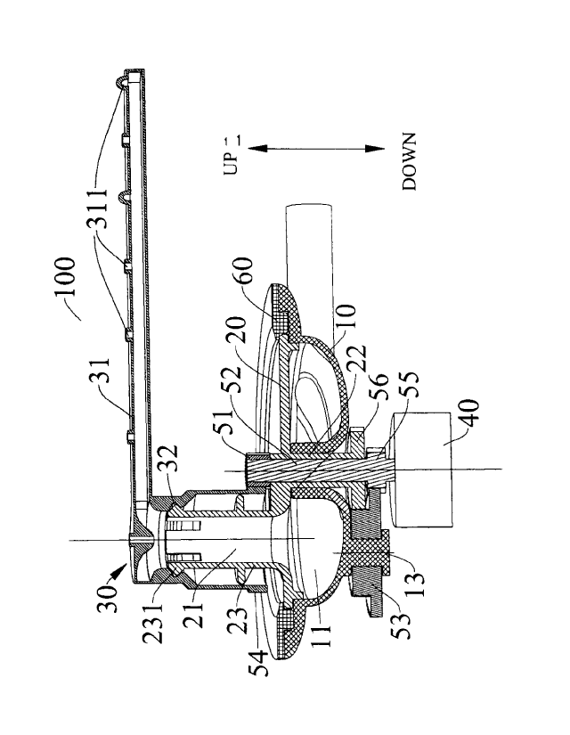
spraying assembly 100;
bottom shell 10; water storage chamber 11; water inlet 12; fixing shaft 13;
spraying seat 20; water input passage 21; mounting portion 22; mounting column
23; locking
tongue 231;
sprayer 30; first spraying arm 301c; second spraying arm 302c; third spraying
arm 303e; spraying
arm 31; spraying orifice 311; mounting groove 32; sleeve 33;
actuator 40;
first sun gear 51; bulge 511; drive shaft 52; groove 521; first gear 53;
planetary gear 54; second
sun gear 55; second gear 56;
pressing plate 60.
DETAILED DESCRIPTION
5
CA 03006690 2018-05-29
. .
PCT/CN2015/06165
ENGLISH TRANSLATION
Embodiments of the present disclosure will be described in detail in the
following, and examples
of the embodiments are illustrated in the drawings. The embodiments described
herein with reference
to drawings are explanatory and used to generally understand the present
disclosure. The embodiments
shall not be construed to limit the present disclosure.
A spraying assembly 100 for a dish washing machine according to embodiments of
a first aspect
of the present disclosure will be described in detail with reference to Figs.
1-8.
As illustrated in Fig. 1 and 2, the spraying assembly 100 for the dish washing
machine according
to embodiments of the present disclosure includes a bottom shell 10, a
spraying seat 20, a sprayer 30
and an actuator 40. Specifically, the bottom shell 10 defines a water storage
chamber 11 therein. The
bottom shell 10 has a water inlet 12 in communication with the water storage
chamber 11. The spraying
seat 20 is rotatably provided to the bottom shell 10. The spraying seat 20 has
a water input passage 21
in communication with the water storage chamber 11. The sprayer 30 includes at
least one spraying arm
31. The sprayer 30 is rotatably provided to spraying seat 20 and a rotation
center of the sprayer 30 is
eccentrically arranged with respect to a rotation center of the spraying seat
20. The sprayer 30 has a
plurality of spraying orifices 311 arranged at intervals, and each spraying
orifice 311 is in
communication with the water input passage 21. The actuator 40 is connected
with the sprayer 30 and
the spraying seat 20 respectively, so as to drive the sprayer 30 and the
spraying seat 20 to rotate around
their respective rotation centers.
That is to say, the spraying assembly 100 for the dish washing machine is
mainly composed of the
bottom shell 10, the spraying seat 20, the sprayer 30 and the actuator 40. The
water storage chamber 11
having an opening upper end is defined in the bottom shell 10. A side wall or
a bottom wall of the
bottom shell 10 is provided with the water inlet 12 in communication with the
water storage chamber
11, thus making it convenient for a system to inject washing water into the
water storage chamber 11.
The spraying seat 20 is disposed on the bottom shell 10 to close an opening
upper end of the bottom
shell 10, and the spraying seat 20 is rotatable with respect to the bottom
shell 10. The spraying seat 20
has the water input passage 21 extending in a vertical direction (an up and
down direction as illustrated
in Fig. 2). The water input passage 21 is in communication with the water
storage chamber 11.
Advantageously, an inner wall of the bottom shell 10 is provided with the
water inlet 12, and the washing
water enters the water storage chamber 11 in a substantially tangential
direction, then flows along an
6
CA 03006690 2018-05-29
PCT/CN2015/06165
ENGLISH TRANSLATION
annular flow channel in the water storage chamber 11 to fill the whole water
storage chamber 11, finally
flows out of the water input passage 21 in the spraying seat 20, and flows to
the respective spraying
arms 31.
Furthermore, the actuator 40 is disposed below the bottom shell 10 and is
connected with the
spraying seat 20, so as to drive the spraying seat 20 to rotate. The sprayer
30 is disposed in an eccentric
position of the spraying seat 20 and is rotatable with respect to the spraying
seat 20. The sprayer 30 has
at least one spraying arm 31. Each spraying arm 31 is provided with the
plurality of spraying orifices
311 arranged at intervals in a length direction of the spraying arm 31. Each
spraying orifice 311 is in
communication with the water input passage 21.
During the operations of the spraying assembly 100 for the dish washing
machine, the actuator 40
drives the spraying seat 20 to rotate around a central axis of the spraying
seat 20. In this process, since
the sprayer 30 is disposed in the eccentric position of the spraying seat 20,
the sprayer 30 has a circular
motion with respect to the spraying seat 20, and also has a motion with a
changing rotation center in
relative to the bottom shell 10. The washing water enters the water storage
chamber 11 through the
water inlet 12 of the bottom shell 10, then flows to each spraying arm 31
through the water input passage
21, and jets out of the plurality of spraying orifices 311, thus reaching the
objective of dish washing,
and also achieving a wide washing coverage.
Thus, in the spraying assembly 100 for the dish washing machine according to
embodiments of
the present disclosure, the sprayer 30 is rotatably disposed in the eccentric
position of the spraying seat
20 which is rotatable with respect to the bottom shell 10, such that each
spraying orifice 311 of the
sprayer 30 has an epicycloid motion track, e.g., a spray-wash area is
substantially quadrate, thereby
enlarging the washing area of the spraying assembly 100, and hence solving the
problem that the dish
washing machine in the related art cannot wash a dead corner of an inner tub.
The spraying assembly
100 for the dish washing machine has a simple structure, a wide washing
coverage, a good washing
effect and a high user experience.
According to an embodiment of the present disclosure, the spraying assembly
100 for the dish
washing machine further includes a driving transmission member and a driven
transmission member.
Specifically, the driving transmission member is connected with the actuator
40 and the sprayer 30, the
driving transmission member is driven by the actuator 40 and drives the
sprayer 30 to rotate, the driven
7
CA 03006690 2018-05-29
PCT/CN201 5/06 165
ENGLISH TRANSLATION
transmission member is connected with the driving transmission member and the
spraying seat 20, and
the driven transmission member is driven by the driving transmission member
and drives the spraying
seat 20 to rotate.
In other words, the spraying assembly 100 for the dish washing machine is
mainly composed of
the bottom shell 10, the spraying seat 20, the sprayer 30, the driving
transmission member, the driven
transmission member and the actuator 40. The driving transmission member is
connected with the
actuator 40 and the sprayer 30 respectively. The driven transmission member is
connected with the
spraying seat 20, and the driving transmission member is fitted with the
driven transmission member.
When the spraying assembly 100 for the dish washing machine starts operating,
the actuator 40 drives
the driving transmission member to move, such that the driving transmission
member drives the sprayer
30 to rotate with respect to the spraying seat 20, and the driving
transmission member also drives the
driven transmission member to move, so as to drive the spraying seat 20 to
rotate with respect to the
bottom shell 10. Thus, by arranging the driving transmission member and the
driven transmission
member to the spraying seat 20 and the bottom shell 10 respectively, a washing
rotation speed required
by a system of the dish washing machine is satisfied and transmissions of
motion and power are
facilitated.
Optionally, according to an embodiment of the present disclosure, the driving
transmission member
includes a first sun gear 51 and a drive shaft 52. A first end of the drive
shaft 52 is connected with the
actuator 40, and the first sun gear 51 is connected with a second end of the
drive shaft 52. The first sun
gear 51 is coaxial with the drive shaft 52 and is driven by the drive shaft
52. The sprayer 30 is provided
with a planetary gear 54 engaged with the first sun gear 51.
Specifically, as illustrated in Fig. 2, the driving transmission member is
mainly composed of the
first sun gear 51 and the drive shaft 52. The drive shaft 52 extends in the
vertical direction (the up and
down direction illustrated in Fig. 2), and the drive shaft 52 is mounted to
the spraying seat 20 and is
rotatable with respect to the spraying seat 20. The first end (a lower end as
illustrated in Fig. 2) of the
drive shaft 52 is connected with the actuator 40, and the second end (an upper
end as illustrated in Fig.
2) of the drive shaft 52 is connected with the first sun gear 51. A lower end
of the sprayer 30 is provided
with the planetary gear 54, and the planetary gear 54 is engaged with the
first sun gear 51.
When the actuator 40 is started, the actuator 40 drives the drive shaft 52 to
rotate around a central
8
CA 03006690 2018-05-29
PCT/CN2015/06165
ENGLISH TRANSLATION
axis of the drive shaft 52, and the upper end of the drive shaft 52 drives the
first sun gear 51 to rotate
around the central axis of the drive shaft 52, such that the spraying seat 20
drives the sprayer 30 to rotate
around the central axis of the drive shaft 52 (a revolution of the sprayer
30). In the meantime, the first
sun gear 51 is engaged with the planetary gear 54, such that the sprayer 30
rotates around a central axis
of the planetary gear 54 (a rotation of the sprayer 30). The lower end of the
drive shaft 52 is fitted with
the driven transmission member, so as to drive the spraying seat 20 to rotate
around the central axis of
the drive shaft 52. Since the planetary gear 54 is located in the eccentric
position of the spraying seat
20, when the spraying assembly 100 for the dish washing machine starts
operating, the sprayer 30 rotates
with respect to the spraying seat 20, and the spraying seat 20 rotates with
respect to the bottom shell 10.
In some specific embodiments of the present disclosure, a gear ratio of the
first sun gear 51 to the
planetary gear 54 is 1:3. Since the first sun gear 51 is externally engaged
with the planetary gear 54, the
rotation and the revolution of the planetary gear 54 have the same direction.
Optionally, the gear ratio
of the first sun gear 51 to the planetary gear 54 is 1:3. For example, the
first sun gear 51 has 30 teeth,
and the planetary gear 54 has 90 teeth. Thus, a ratio of a pitch radius R1 of
the first sun gear 51 to a
pitch radius R2 of the planetary gear 54 is 1:3 as well, and a radius R3 of a
revolution trajectory of the
planetary gear 54 is equal to a sum of R1 and R2.
Furthermore, due to the gear ratio and the external engagement between the
first sun gear 51 and
the planetary gear 54, ends of the respective spraying arms 31 present a
prolate epicycloid motion track,
thus covering a rectangle area better. Moreover, an angle of a phase
difference between motion tracks
of two spraying arms 31 is equal to 3/2 times of an angle of a phase
difference between the two spraying
arms 31.
For a single spraying arm 31, each spraying orifice 311 of the single spraying
arm 31 has a
characteristic epicycloid motion track. For the relatively outer spraying
orifice 311, a distance from the
spraying orifice 311 to a center of the planetary gear 54 is larger than four
times of the pitch radius R2
of the planetary gear 54, and the motion track of such spraying orifice 311 is
a prolate epicycloid. The
curve does not cross itself, front and rear parts of the curve are curved
outwards, and left and right parts
of the curve are slightly curved inwards. With the position of the spraying
orifice 311 moving inwards,
the inwards curved portion of the prolate epicycloid motion track gradually
gets obvious, a radius of a
transition rounded corner is gradually reduced, and four corners gradually
become sharp. When the
9
CA 03006690 2018-05-29
PCT/CN2015/06165
ENGLISH TRANSLATION
distance from the spraying orifice 311 to the center of the planetary gear 54
is equal to four times of the
pitch radius R2 of the planetary gear 54, the transition rounded corner at the
inwards curved portion is
just disappeared, the overall prolate epicycloid motion track of the spraying
orifice 311 is a kidney-
shaped curve with the front and rear parts thereof being curved outwards.
Then, for the relatively inner
spraying orifice 311, the distance from such spraying orifice 311 to the
center of the planetary gear 54
is less than four times of the pitch radius R2 of the planetary gear 54, the
inwards curved portion of the
prolate epicycloid motion track has a crossed shape. Finally, for the spraying
orifice 311 which is located
at the center of the planetary gear 54, the motion track of such spraying
orifice 311 is a revolution
trajectory, i.e., a circle of radius R3.
Thus, the gear ratio of the first sun gear 51 to the planetary gear 54 is set
as 1:3, such that each
spraying orifice 311 of the sprayer 30 has the epicycloid motion track, e.g.,
the spray-wash area is
substantially rectangle, thereby enlarging the washing area of the spraying
assembly 100, and hence
solving the problem that the dish washing machine in the related art cannot
wash the dead corner of the
inner tub. The spraying assembly 100 for the dish washing machine has a simple
structure, a wide
washing coverage, a good washing effect and a high user experience.
In other specific embodiments of the present disclosure, the gear ratio of the
first sun gear 51 and
the planetary gear 54 is 1:5. For example, the first sun gear 51 has 20 teeth,
and the planetary gear 54
has 100 teeth. Thus, the ratio of the pitch radius R1 of the first sun gear 51
to the pitch radius R2 of the
planetary gear 54 is 1:5 as well, and the radius R3 of the revolution
trajectory of the planetary gear 54
is equal to the sum of RI and R2. Furthermore, due to the gear ratio and the
external engagement
between the first sun gear 51 and the planetary gear 54, the ends of the
respective spraying arms 31 each
present the prolate epicycloid motion track, thus covering a square area
better. Moreover, an angle of a
phase difference between motion tracks of two spraying arms 31 is equal to 5/4
times of an angle of a
phase difference between the two spraying arms 31.
For a single spraying arm 31, each spraying orifice 311 of the single spraying
arm 31 has a
characteristic epicycloid motion track. For the relatively outer spraying
orifice 311, the distance from
such spraying orifice 311 to the center of the planetary gear 54 is larger
than six times of the pitch radius
R2 of the planetary gear 54, the motion track of the spraying orifice 311 is a
four-leaved prolate
epicycloid. The curve does not cross itself, and four corners of the curve are
curved outwards. With the
CA 03006690 2018-05-29
PCT/CN20 15/06165
ENGLISH TRANSLATION
position of the spraying orifice 311 moving inwards, the four inwards curved
portions of the motion
track gradually get obvious, the radius of the transition rounded corner is
gradually reduced, and hence
the corner gradually becomes sharp. When the distance from the spraying
orifice 311 to the center of
the planetary gear 54 is equal to six times of the pitch radius R2 of the
planetary gear 54, i.e., five times
of the revolution radius R3, the transition rounded corners at the four
inwards curved portions are just
disappeared and become into four pointed corners. Then, for the relatively
inner spraying orifice 311,
the distance from the spraying orifice 311 to the center of the planetary gear
54 is less than six times of
the pitch radius R2 of the planetary gear 54, the inwards curved portion of
the prolate epicycloid motion
track defines has a crossed shape. Finally, for the spraying orifice 311 which
is located at the center of
the planetary gear 54, the motion track of such spraying orifice 311 is a
revolution trajectory, i.e., a
circle of radius R3.
During the operation of the spraying assembly 100 for the dish washing
machine, the actuator 40
drives the spraying seat 20 to rotate around the central axis of the spraying
seat 20. In this process, since
the sprayer 30 is disposed in the eccentric position of the spraying seat 20,
the sprayer 30 has a circular
motion with respect to the spraying seat 20, and also has a motion with a
changing rotation center with
respect to the bottom shell 10. The washing water enters the water storage
chamber 11 through the water
inlet 12 of the bottom shell 10, then flows to each spraying arm 31 through
the water input passage 21,
and jets out of the plurality of spraying orifices 311, thus reaching the
objective of dish washing, and
also achieving a wide washing coverage.
Thus, the sprayer 30 is rotatably disposed in the eccentric position of the
spraying seat 20 which is
rotatable with respect to the bottom shell 10, and the gear ratio of the first
sun gear 51 to the planetary
gear 54 is set as 1:5, such that each spraying orifice 311 of the sprayer 30
has an epicycloid motion
track, e.g., the spray-wash area is substantially square, thereby enlarging
the washing area of the
spraying assembly 100, solving the problem that the dish washing machine in
the related art cannot
wash the dead corner of the inner tub. The spraying assembly 100 for the dish
washing machine has a
simple structure, a wide washing coverage, a good washing effect and a high
user experience.
Optionally, the driven transmission member is configured as a first gear 53
provided to the bottom
shell 10, the first end of the drive shaft 52 is provided with a second sun
gear 55 engaged with the first
gear 53, the spraying seat 20 is provided with a second gear 56 engaged with
the first gear 53, the second
11
CA 03006690 2018-05-29
' PCT/CN2015/06165
ENGLISH TRANSLATION
sun gear 55 cooperates with the first gear 53 and the second gear 56 to drive
the spraying seat 20 to
rotate.
Specifically, as illustrated in Fig. 2, the second sun gear 55 is fixedly
provided to the lower end of
the drive shaft 52, the bottom shell 10 is provided with the first gear 53
which is rotatable, and the lower
end of the spraying seat 20 is provided with the second gear 56. The first
gear 53 includes two toothed
parts having different amounts of teeth and the two toothed parts are engaged
with the second gear 56
and the second sun gear 55 correspondingly. When the spraying assembly 100 for
the dish washing
machine starts operating, the drive shaft 52 drives the first sun gear 51 and
the second sun gear 55 to
rotate around the central axis of the drive shaft 52. The second sun gear 55
on the drive shaft 52 is
engaged with the first gear 53, such that the first gear 53 drives the
spraying seat 20 to rotate around the
central axis of the drive shaft 52 by the engagement with the second gear 56.
The first sun gear 51 on
the drive shaft 52 drives the sprayer 30 to rotate around the central axis of
the planetary gear 54 by the
engagement with the planetary gear 54. Thus, the spraying assembly 100 for the
dish washing machine
has a transmission system which is simple in structure, easy to dismount and
mount, effortless to operate,
low in cost and also can transmit motions accurately.
Optionally, as illustrated in Fig. 4, a lower end of the bottom shell 10 is
provided with a fixing
shaft 13, the first gear 53 is mounted to the fixing shaft 13 and is rotatable
with respect to the fixing
shaft 13, thus facilitating the mounting of the first gear 53, and thereby
achieving functional
requirements of the spraying assembly 100 for the dish washing machine.
As illustrated in Fig. 5, according to an embodiment of the present
disclosure, the spraying seat 20
has a mounting portion 22 penetrating the bottom shell 10 and extending
downwards, and the mounting
portion 22 is configured as a hollow column coaxial with the drive shaft 52.
The upper end of the drive
shaft 52 passes through the mounting portion 22 to be connected with the first
sun gear 51, and the
lower end of the drive shaft 52 is provided with the second sun gear 55. The
first gear 53 is disposed at
a bottom portion of the bottom shell 10, and a lower end of the mounting
portion 22 is provided with
the second gear 56.
Specifically, the mounting portion 22 is located in the center of the spraying
seat 20 and extends
downwards in an axial direction (an up and down direction as illustrated in
Fig. 5) of the spraying seat
20. The mounting portion 22 defines a cavity therein for mounting the drive
shaft 52, and the drive shaft
12
CA 03006690 2018-05-29
. PCT/CN20 1 5/061 65
ENGLISH TRANSLATION
52 penetrates the cavity and is rotatable with respect to the mounting portion
22. The upper and lower
ends of the drive shaft 52 extend out of the cavity, so as to be provided with
the first sun gear 51 and
the second sun gear 55 correspondingly. The second sun gear 55 is engaged with
the first gear 53 on the
fixing shaft 13 of the bottom shell 10, and the first sun gear 51 is engaged
with the planetary gear 54 of
the sprayer 30.
Furthermore, the spraying seat 20 is provided with a mounting column 23
eccentrically provided
with respect to a rotation center of the spraying seat 20, the mounting column
23 defines the water input
passage 21 therein, and the sprayer 30 is fitted over the mounting column 23
and is rotatable with respect
to the mounting column 23. Specifically, the sprayer 30 includes a sleeve 33
extending in the vertical
direction, and the planetary gear 54 is provided at a lower end of the sleeve
33. When the sprayer 30 is
mounted to the spraying seat 20, the spraying seat 20 serves as a planetary
gear carrier for the planetary
gear 54, so as to ensure the revolution trajectory of the planetary gear 54.
At an upper end of the sleeve
33 of the sprayer 30, one or more spraying arms 31 extend outwards from the
center of the planetary
gear 54, and each spraying arm 31 is provided with a plurality of spraying
orifices 311. Advantageously,
a part of the spraying orifices 311 is used for washing, and other spraying
orifices 311 are mostly used
for forcing a horizontal rotation of the spraying arm 31 as well as the
planetary gear 54, thereby
providing power for the rotation of the sprayer 30.
Optionally, as illustrated in Figs. 5 and 6, the mounting column 23 is
provided with a plurality of
locking tongues 231 arranged at intervals, and an inner wall of the sprayer 30
is provided with a
mounting groove 32 fitted with the locking tongues 231. Thus, it is ensured
that the sprayer 30 can be
snapped with the spraying seat 20, so as to avoid the sprayer 30 from being
disengaged with the spraying
seat 20 during operations, and also, the relative rotation between the sprayer
30 and the spraying seat
20 is ensured, such that rotations of the sprayer 30 and the planetary gear 54
can be achieved.
According to an embodiment of the present disclosure, the upper end of the
drive shaft 52 is
provided with a plurality of grooves 521 arranged at intervals, and an inner
ring of the first sun gear 51
is provided with a plurality of bulges 511 correspondingly fitted with the
grooves 521. Specifically, as
illustrated in Fig. 7, a side wall of the upper end of the drive shaft 52 is
provided with the plurality of
grooves 521 arranged at intervals in its circumferential direction, and an
inner wall of the first sun gear
51 is provided with the plurality of bulges 511 correspondingly fitted with
the grooves 521, thus
13
CA 03006690 2018-05-29
PCT/CN2015/06165
ENGLISH TRANSLATION
ensuring the first sun gear 51 to be fixedly connected with the drive shaft
52, and hence improving the
connection reliability of the spraying assembly 100 for the dish washing
machine.
In some specific embodiments of the present disclosure, the end of the drive
shaft 52 which is fitted
with the first sun gear 51 is configured as a spline shaft, and the spline
shaft is snapped with the first
sun gear 51.
Specifically, an inner wall of the first sun gear 51 is provided with a
splined hole, and four bulges
511 are provided in the splined hole. When mounted, the first sun gear 51 is
sleeved onto the spline
shaft of the drive shaft 52, till the four bulges 511 are correspondingly
locked in four grooves 521 of
the spline shaft, thereby achieving the fixation of the first sun gear 51.
Such connection structure can
achieve the fit between the drive shaft 52 and the first sun gear 51, and is
simple in structure, easy to
produce and high in efficiency of mounting and dismounting.
Preferably, according to an embodiment of the present disclosure, the spraying
seat 20 is a rotary
body, and a central axis of the spraying seat 20 coincides with the central
axes of the bottom shell 10
and the drive shaft 52. In addition, the spraying assembly 100 for the dish
washing machine further
includes a pressing plate 60, the pressing plate 60 is provided on the bottom
shell 10 and is connected
with the bottom shell 10, and at least a part of the pressing plate 60 is
pressed on the spraying seat 20.
Specifically, as illustrated in Fig. 2, the spraying seat 20 is located
between the first sun gear 51
and the bottom shell 10, the central axes of the spraying seat 20, the first
sun gear 51 and the bottom
shell 10 coincide with one another, and a main body of the spraying seat 20 is
a round rotary disk. When
mounted, the water storage chamber 11 of the bottom shell 10 is covered by the
spraying seat 20 first,
and the mounting portion 22 of the spraying seat 20 extends into the water
storage chamber 11. Then,
an outer ring of the spraying seat 20 is pressed by the pressing plate 60. At
this time, the drive shaft 52
is inserted into the mounting portion 22 and extends out of the spraying seat
20, and then the first sun
gear 51 is fitted with the upper end of the drive shaft 52. Finally, the
sprayer 30 is mounted to the
mounting column 23 of the spraying seat 20, and the planetary gear 54 on the
sprayer 30 is engaged
with the first sun gear 51 on the drive shaft 52. Therefore, the spraying seat
20 is embedded between
the pressing plate 60 and the bottom shell 10, and can rotate with respect to
the pressing plate 60 and
the bottom shell 10.
Preferably, according to an embodiment, the second sun gear 55 is integrally
formed with the drive
14
CA 03006690 2018-05-29
PCT/CN2015/06165
ENGLISH TRANSLATION
shaft 52, the planetary gear 54 is integrally formed with the sprayer 30, and
the second gear 56 is
integrally formed with the spraying seat 20. Thus, an integrally formed
structure ensures stability of the
structure and property of the spraying assembly 100 for the dish washing
machine, is convenient to
mold and easy to produce, and also omits needless assembly parts and
connecting processes, thus greatly
improving the assembly efficiency of the spraying assembly 100 for the dish
washing machine, and
ensuring the connection reliability of the spraying assembly 100 for the dish
washing machine.
Moreover, the integrally formed structure has high overall strength and
stability, is easy to assemble and
provides a long service life.
The spraying assembly 100 for the dish washing machine according to
embodiments of the present
disclosure will be described with reference to specific embodiments
illustrated in Figs. 1-15.
Embodiment One
As illustrated in Figs. 1-9, in the present embodiment, the first sun gear 51
is fixed in a center
position at the bottom of the inner tub of the dish washing machine, the inner
wall of the first sun gear
51 is provided with the splined hole, and the four bulges 511 are provided in
the splined hole defines.
When mounted, the first sun gear 51 is sleeved onto the spline shaft of the
drive shaft 52, till the four
bulges 511 are correspondingly locked in four grooves 521 of the spline shaft,
thereby achieving the
fixed connection of the first sun gear 51 with the drive shaft 52. The water
storage chamber 11 in the
bottom shell 10 is an annular flow channel, and the side wall of the bottom
shell 10 is provided with the
water inlet 12, such that the washing water enters the water storage chamber
11 in the substantially
tangential direction, then flows along the annular flow channel to fill the
whole water storage chamber
11, finally flows out of the water input passage 21 of the spraying seat 20,
and flows to the spraying
arm 31.
As illustrated in Fig. 9, in the present embodiment, the gear ratio of the
first sun gear 51 to the
planetary gear 54 is 1:3, in which the spraying assembly 100 for the dish
washing machine includes one
spraying arm 31. According to the gear ratio and the external engagement
between the first sun gear 51
and the planetary gear 54, the end of the spraying arm 31 presents the prolate
epicycloid motion track
which is substantially rectangle, thus achieving a great coverage of a
rectangle spraying area.
Specifically, a curvilinear equation of the prolate epicycloid motion track
includes:
CA 03006690 2018-05-29
PCT/CN2015/06165
ENGLISH TRANSLATION
X= (R1+R2)*cos(ang)-D*cos [(R1*ang/R2]
y=-(R1+R2)*sin(ang)+D*sin[(R1*ang/R2].
D denotes a distance between the spraying orifice 311 and the center of the
planetary gear 54, R1
denotes a pitch radius of the first sun gear 51, and R2 denotes a pitch radius
of the planetary gear 54.
For example, modules of the first sun gear 51 and the planetary gear 54 are
set as 0.5, the first sun
gear 51 has 30 teeth, and the planetary gear 54 has 90 teeth. It can be seen
that, a ratio of the pitch radius
R1 of the first sun gear 51 to the pitch radius R2 of the planetary gear 54 is
also 1:3. Specifically, R1 is
equal to 7.5mm, R2 is equal to 22.5mm, and a radius R3 of a revolution
trajectory of the planetary gear
54 is equal to a sum of R1 and R2, i.e. 30mm.
Furthermore, the distance from the relatively outer spraying orifice 311 in
the spraying arm 31 to
the center of the planetary gear 54 is larger than four times of the pitch
radius R2 of the planetary gear
54, i.e. 90mm, and the motion track of such spraying orifice 311 is the
prolate epicycloid. The curve
does not cross itself, front and rear parts of the curve are curved outwards,
and left and right parts of the
curve are slightly curved inwards. With the position of the spraying orifice
311 moving inwards, the
inwards curved portion of the prolate epicycloid motion track gradually gets
obvious, a radius of a
transition rounded corner is gradually reduced, and four corners gradually
become sharp. When the
distance from the spraying orifice 311 to the center of the planetary gear 54
is equal to 90mm, the
transition rounded corner at the inwards curved portion is just disappeared,
the overall prolate epicycloid
motion track of the spraying orifice 311 is a kidney-shaped curve with the
front and rear parts thereof
being curved outwards. Then, for the relatively inner spraying orifice 311,
the distance from such
spraying orifice 311 to the center of the planetary gear 54 is less than 90mm,
and the inwards curved
portion of the prolate epicycloid motion track has a crossed shape. Finally,
for the spraying orifice 311
which is located in the center of the planetary gear 54, the motion track of
such spraying orifice 311 is
the revolution trajectory, i.e., a circle of radius 30mm.
When the spraying assembly 100 for the dish washing machine operates, due to a
recoiling action
of water spraying by a part of the spraying orifices 311 in the spraying arm,
the spraying arm 31 along
with the planetary gear 54 are driven to rotate. Due to the gear engagement,
the spraying arm 31 along
with the planetary gear 54 orbit the first sun gear 51 while rotating. The
rotation and the revolution have
the same direction, and a rotation speed ratio of the rotation to the
revolution is 1:3.
16
CA 03006690 2018-05-29
,
PCT/CN2015/06165
ENGLISH TRANSLATION
Embodiment Two
As illustrated in Fig. 10, in the present embodiment, the gear ratio of the
first sun gear 51 to the
planetary gear 54 is 1:3, and the sprayer 30 has two spraying arms 31. That
is, two spraying arms 31
extend outwards from the center of the planetary gear 54, and the two spraying
arms 31 are diagonally
arranged with a phase difference of 1800 therebetween. The two spraying arms
31 each are provided
with a group of spraying orifices 311. According to the gear ratio 1:3 and the
external engagement
between the first sun gear 51 and the planetary gear 54, motion tracks of two
spraying arms 31 have a
phase difference, which is equal to 3/2 times of the phase difference between
the two spraying arms 31,
and specifically is 270 . That is, the two motion tracks are perpendicular to
each other.
The spraying orifices 311 in the two spraying arms 31 have a characteristic
prolate epicycloid
motion track respectively, whose features are consistent with descriptions of
Embodiment One, and will
not be elaborated herein. Moreover, since the motion tracks of the two groups
of spraying orifices 311
in the two spraying arms 31 has the phase difference of 270 , the two groups
of motion tracks are
crossed while being perpendicular to each other, thus obtaining a great
washing coverage effect within
the rectangle central area.
Embodiment Three
As illustrated in Fig. 11, in the present embodiment, the gear ratio of the
first sun gear 51 is the
planetary gear 54 is 1:3, and the sprayer 30 has three spraying arms 31, that
is, three spraying arms 31
extend outwards from the center of the planetary gear 54. Each two of the
three spraying arms 31 are
spaced apart from each other by an interval of 120 . Each spraying arm 31 is
provided with a group of
spraying orifices 311. According to the gear ratio 1:3 and the external
engagement between the first sun
gear 51 and the planetary gear 54, motion tracks of three spraying arms 31
have a phase difference,
which is equal to 3/2 times of a phase difference between the three spraying
arms 31, i.e., 180 and 360 .
Each group of spraying orifices 311 in the three spraying arms 31 has a
characteristic prolate
epicycloid motion track, whose features are consistent with the descriptions
of Embodiment One, and
will not be elaborated herein. Moreover, since the motion tracks of the three
groups of spraying orifices
311 have the phase difference of 180 or 360 , the three motion tracks have a
same orientation, and are
17
CA 03006690 2018-05-29
PCT/CN2015/06165
ENGLISH TRANSLATION
superimposed to form denser motion tracks of the spraying orifices 311, thus
achieve a better washing
coverage effect within the rectangle spraying area.
Thus, the spraying assembly 100 for the dish washing machine can achieve a
great washing
coverage effect by adjusting the amount of the spraying arms 31 and the amount
of the spraying orifices
311, such that it is ensured the rectangle spraying area of the spraying
assembly 100 for the dish washing
machine is matched with the rectangle inner tub of the dish washing machine,
thereby ensuring an all-
around and multi-angle cleaning rate.
Embodiment Four
As illustrated in Fig. 12, in the present embodiment, the gear ratio of the
first sun gear 51 to the
planetary gear 54 is 1:5, and the spraying assembly 100 for the dish washing
machine includes one
spraying arm 31. According to the gear ratio and the external engagement
between the first sun gear 51
and the planetary gear 54, the end of the spraying arm 31 presents a prolate
epicycloid motion track
which is substantially square, thus achieving a great coverage of a square
spraying area. Specifically, a
curvilinear equation of the prolate epicycloid motion track includes:
x= (R1+R2)*cos(ang)-D*cos [(R1*ang/R2]
y=-(R1+R2)*sin(ang)+D*sin[(R1*ang/R2].
D denotes a distance from the spraying orifice 311 to the center of the
planetary gear 54, R1 denotes
a pitch radius of the first sun gear 51, and R2 denotes a pitch radius of the
planetary gear 54.
For example, modules of the first sun gear 51 and the planetary gear 54 both
are 0.5, the first sun
gear 51 has 20 teeth, and the planetary gear 54 has 100 teeth. It can be seen
that, a ratio of the pitch
radius R1 of the first sun gear 51 to the pitch radius R2 of the planetary
gear 54 is also 1:5. Specifically,
RI is equal to 5mm, R2 is equal to 25mm, and a radius R3 of a revolution
trajectory of the planetary
gear 54 is equal to a sum of R1 and R2, i.e. 30mm.
Furthermore, according to the gear ratio 1:5 and the external engagement
between the first sun gear
51 and the planetary gear 54, as well as a rotation speed ratio 5:1 of the
first sun gear 51 to the spraying
seat 20 achieved by a speed-setting gear train mechanism, it can be seen that,
a rotation speed of the
planetary gear 54 is 1/5 of a rotation speed of the spraying seat 20. That is,
it is can be further seen that
the spraying orifice 311 in the spraying arm 31 presents a special prolate
epicycloid motion track. For
18
CA 03006690 2018-05-29
PCT/CN2015/06165
ENGLISH TRANSLATION
the relatively outer spraying orifice 311, a distance from such spraying
orifice 311 to the center of the
planetary gear 54 is larger than six times (i.e., 150mm) of the pitch radius
R2 of the planetary gear 54,
and the motion track of such spraying orifice 311 is a four-leaved prolate
epicycloid. The curve does
not cross itself, and four corners of the curve are curved outwards. With the
position of the spraying
orifice 311 moving inwards, four inwards curved portions of the motion track
gradually get obvious, a
radius of the transition rounded corner is gradually reduced, and hence the
corner gradually becomes
sharp. When the distance from the spraying orifice 311 to the center of the
planetary gear 54 is equal to
150mm, i.e., five times of a revolution radius R3, the transition rounded
corners at the four inwards
curved portions are just disappeared and become into four pointed corners.
Then, for the relatively inner
spraying orifice 311, the distance from such spraying orifice 311 to the
center of the planetary gear 54
is less than 150mm, and the prolate epicycloid motion track of such spraying
orifice 311 has a crossed
shape at the inwards curved portion. Finally, for the spraying orifice 311
located in the center of the
planetary gear 54, the motion track of such spraying orifice 311 is a
revolution trajectory, i.e., a circle
of radius 30mm.
When the spraying assembly 100 for the dish washing machine operates, due to a
recoiling action
of water spraying by a part of the spraying orifices 311 in the spraying arm
31, the spraying arm 31
along with the planetary gear 54 are driven to rotate. Due to the gear
engagement, the spraying arm 31
along with the planetary gear 54 orbit the first sun gear 51 while rotating.
The rotation and the revolution
have the same direction, and a rotation speed ratio of the rotation to the
revolution is 1:5.
Embodiment Five
As illustrated in Fig. 13, in the present embodiment, the gear ratio of the
first sun gear 51 to the
planetary gear 54 is 1:5, and the sprayer 30 has two spraying arms 31. That
is, two spraying arms 31
extend outwards from the center of the planetary gear 54, and the two spraying
arms 31 are diagonally
arranged with a phase difference of 180 therebetween. The two spraying arms
31 each are provided
with a group of spraying orifices 311. According to the gear ratio 1:5 and the
external engagement
between the first sun gear 51 and the planetary gear 54, motion tracks of the
two spraying arms 31 have
a phase difference, which is equal to 5/4 times of a phase difference between
the two spraying arms 31,
and specifically is 225 . In this case, the inwards curved portion in the
motion track of one of the
19
CA 03006690 2018-05-29
PCT/CN2015/06165
ENGLISH TRANSLATION
spraying arms 31 is corresponding to the outwards curved portion in the motion
track of the other one
of the spraying arms 31.
The spraying orifices 311 in the two spraying arms 31 have the characteristic
prolate epicycloid
motion tracks respectively, whose features are consistent with the
descriptions of Embodiment Four,
and will not be elaborated herein. Moreover, since the motion tracks of the
two groups of spraying
orifices 311 in the two spraying arms 31 has the phase difference of 225 , the
two motion tracks are
interwoven into a net in a central spraying area, thus reaching a great
washing coverage effect.
Embodiment Six
As illustrated in Fig. 14, in the present embodiment, the gear ratio of the
first sun gear 51 to the
planetary gear 54 is 1:5, and the sprayer 30 has three spraying arms 31. That
is, three spraying arms 31
extend outwards from a center of the planetary gear 54. A first spraying arm
301c is spaced apart from
a second spraying arm 302c by an angle of 144 , and the first spraying arm
301c is spaced apart from a
third spraying arm 303c by an angle of 144 . That is, an included angle
between the second spraying
arm 302c and the third spraying arm 303c is 72 . Lengths of the second
spraying arm 302c and the third
spraying arm 303c are about 0.618 times of a length of the first spraying arm
301c, thereby ensuring a
balance of the overall sprayer 30. Each spraying arm 31 is provided with a
group of spraying orifices
311. Three motion tracks of the first spraying arm 301c, the second spraying
arm 302c and the third
spraying arm 303c have phase differences thereamong, which are equal to 5/4
times of the phase
differences of 72 and 144 among the spraying arms 31, i.e., 90 and 180 ,
and therefore the three
motion tracks have the same shape and orientation.
Each group of spraying orifices 311 in the three spraying arms 31 has a
characteristic prolate
epicycloid motion track, whose features are consistent with the descriptions
of Embodiment Four, and
will not be elaborated herein. Moreover, since the phase differences among the
motion tracks of the
three groups of spraying orifices 311 are 90 and 180 correspondingly, the
three motion tracks have
the same shape and orientation, and are superimposed to form dense motion
tracks of the spraying
orifices 311, thus achieving a great washing coverage effect in a square
spraying area.
Embodiment Seven
CA 03006690 2018-05-29
PCT/CN2015/06165
ENGLISH TRANSLATION
As illustrated in Fig. 15, in the present embodiment, the gear ratio of the
first sun gear 51 to the
planetary gear 54 is 1:5, and the sprayer 30 has five spraying arms 31. That
is, five spraying arms 31
extend outwards from a center of the planetary gear 54. Two adjacent spraying
arms 31 are spaced apart
from each other by an angle of 72 . Each spraying arm 31 is provided with a
group of spraying orifices
311. According to the gear ratio 1:5 and the external engagement between the
first sun gear 51 and the
planetary gear 54, motion tracks of the five spraying arms 31 have phase
differences thereamong, which
are equal to 5/4 times of the phase differences of 72 among the three
spraying arms 31, i.e., 90 , and
therefore the five motion tracks have the same shape and orientation.
Each group of spraying orifices 311 in the five spraying arms 31 has a
characteristic prolate
epicycloid motion track, whose features are consistent with the descriptions
of Embodiment Four, and
will not be elaborated herein. Moreover, since the motion tracks of the five
groups of spraying orifices
311 have the phase differences of 90 , the five motion tracks have the same
shape and orientation, and
finally are superimposed to form dense motion tracks of the spraying orifices
311, thus achieving a great
washing coverage effect in a square spraying area.
Thus, the spraying assembly 100 for the dish washing machine can achieve a
better washing
coverage effect by adjusting the amount of the spraying arms 31 and the amount
of the spraying orifices
311, so as to ensure that the square spraying area of the spraying assembly
100 for the dish washing
machine is matched with the square inner tub of the dish washing machine,
thereby achieving an all-
around and multi-angle cleaning rate.
A dish washing machine according to embodiments of a second aspect of the
present disclosure
includes the spraying assembly 100 for the dish washing machine according to
the above-mentioned
embodiments. Since the spraying assembly 100 for the dish washing machine
according to embodiments
of the present disclosure has the above-mentioned technical effects, the dish
washing machine according
to embodiments of the present disclosure has the above-mentioned effects as
well. That is, the dish
washing machine has a simple structure and a wide washing coverage, and
provides a quadrate (such
as square and rectangle) spraying area matched with a quadrate inner tub of
the dish washing machine,
thereby solving the problem that the dish washing machine in the related art
cannot wash a dead corner
of the inner tub. Thus, the dish washing machine has a great washing effect
and a high user experience.
Other components and operations of the dish washing machine according to
embodiments of the
21
CA 03006690 2018-05-29
PCT/CN2015/06165
ENGLISH TRANSLATION
present disclosure are known to those skilled in the art, and will not be
elaborated herein.
In the specification, it is to be understood that terms such as "central,"
"longitudinal," "lateral,"
"length," "width," "thickness," "upper," "lower," "front," "rear," "left,"
"right," "vertical," "horizontal,"
"top," "bottom," "inner," "outer," "clockwise," "counterclockwise," "axial,"
"radial" and
"circumferential" should be construed to refer to the orientation as then
described or as illustrated in the
drawings under discussion. These relative terms are for convenience of
description and do not require
that the present disclosure be constructed or operated in a particular
orientation.
In addition, terms such as "first" and "second" are used herein for purposes
of description and are
not intended to indicate or imply relative importance or significance or to
imply the number of indicated
technical features. Thus, the feature defined with "first" and "second" may
comprise one or more of this
feature. In the description of the present disclosure, "a plurality of" means
two or more than two, unless
specified otherwise.
In the present disclosure, unless specified or limited otherwise, the terms
"mounted," "connected,"
"coupled," "fixed" and the like are used broadly, and may be, for example,
fixed connections, detachable
connections, or integral connections; may also be mechanical or electrical
connections; may also be
direct connections or indirect connections via intervening structures; may
also be inner communications
of two elements, which can be understood by those skilled in the art according
to specific situations.
In the present disclosure, unless specified or limited otherwise, a structure
in which a first feature
is "on" or "below" a second feature may include an embodiment in which the
first feature is in direct
contact with the second feature, and may also include an embodiment in which
the first feature and the
second feature are not in direct contact with each other, but are contacted
via an additional feature
formed therebetween. Furthermore, a first feature "on," "above," or "on top
of" a second feature may
include an embodiment in which the first feature is right or obliquely "on,"
"above," or "on top of' the
second feature, or just means that the first feature is at a height higher
than that of the second feature;
while a first feature "below," "under," or "on bottom of' a second feature may
include an embodiment
in which the first feature is right or obliquely "below," "under," or "on
bottom of' the second feature,
or just means that the first feature is at a height lower than that of the
second feature.
Reference throughout this specification to "an embodiment," "some
embodiments," "one
embodiment", "another example," "an example," "a specific example," or "some
examples," means that
22
CA 03006690 2018-05-29
PCT/CN2015/06165
ENGLISH TRANSLATION
a particular feature, structure, material, or characteristic described in
connection with the embodiment
or example is included in at least one embodiment or example of the present
disclosure. Thus, the
appearances of the phrases such as "in some embodiments," "in one embodiment",
"in an embodiment",
"in another example," "in an example," "in a specific example," or "in some
examples," in various
places throughout this specification are not necessarily referring to the same
embodiment or example
of the present disclosure. Furthermore, the particular features, structures,
materials, or characteristics
may be combined in any suitable manner in one or more embodiments or examples.
Although explanatory embodiments have been illustrated and described, it would
be appreciated
by those skilled in the art that the above embodiments cannot be construed to
limit the present disclosure,
and changes, alternatives, and modifications can be made in the embodiments
without departing from
spirit, principles and scope of the present disclosure.
23