Note: Descriptions are shown in the official language in which they were submitted.
CA 03006801 2018-05-29
WO 2017/106723
PCT/US2016/067289
WHEEL COMPRISING A NON-PNEUMATIC TIRE
CROSS-REFERENCE TO RELATED APPLICATION
This application claims priority from U.S. Provisional Patent Application
62/268,243 filed
on December 16, 2015 and hereby incorporated by reference herein.
FIELD
The invention relates generally to wheels comprising non-pneumatic tires
(NPTs), such
as for vehicles (e.g., all-terrain vehicles (ATVs); industrial vehicles such
as construction
vehicles; agricultural vehicles; automobiles and other road vehicles; etc.)
and/or other
devices.
BACKGROUND
Wheels for vehicles and other devices may comprise non-pneumatic tires
(sometimes
referred to as NPTs) instead of pneumatic tires.
Pneumatic tires have a commanding market share due to several virtues. For
example,
a pneumatic tire may offer high vertical compliance and the ability to have a
large
deflection before impact occurs with the wheel, which is usually metallic. The
pneumatic
tire may develop a large contact area, which is efficient for transferring
tangential and
longitudinal forces from the tire/road contact area to the vehicle. The
pneumatic tire is
also able to envelop obstacles. Added to these is the fact that the pneumatic
tire, with
over 100 years of refinement, is a mature product and therefore inexpensive to
produce.
In particular, the high compliance and potential for large deflection are
major pneumatic
tire virtues in the off-road vehicle market. For example, in the ATV industry,
a 650 mm
(26") outer diameter tire can be mounted to a 12" diameter rim. When inflated
to 0.08
1
CA 03006801 2018-05-29
WO 2017/106723
PCT/US2016/067289
MPa (12 psi), a design load of 240 kgf (kilogram-force) is reached with 20 mm
of
deflection, for a vertical stiffness of only 20 kgf/mm. A total deflection of
125 mm is
possible, before the tire is pinched between the ground and the rim. Thus, a
ratio
between the tire deflection and the tire radius is 120 mm to 325 mm, or
0.38:1. The tire
deflection is almost 40% the tire radius.
Certain vehicles like some ATVs may be capable of speeds in excess of 100 kph.
Even
at speeds above 50 kph, impacts with rocks or other hard obstacles result in
an
imposed tire deflection. The suspension cannot react to essentially an
instantaneous
impact. Thus, the ability of the tire to locally deform and envelop such
obstacles is a
highly desired trait.
Non-pneumatic tires are used in certain applications. They are sometimes used
in
highly aggressive environments where flats are a problem for pneumatic tires.
NPTs are
not inflated and have no gas-filled bladder like a pneumatic tire. Examples of
use for
NPTs would include certain off-road usage like construction job sites and
waste
management sites. In these sites, NPT disadvantages are outweighed by their
damage
tolerance.
Yet, this damage tolerance usually comes with a trade-off. With reference to
the
pneumatic tire virtues just mentioned, a non-pneumatic tire may suffer in
terms of its
ability to sustain a large vertical deflection, and/or to develop a large
contact area.
Additionally, NPTs may be more complex and expensive to manufacture.
For these and other reasons, there is a need to improve wheels comprising non-
pneumatic tires.
SUMMARY
According to various aspects of the invention, there is provided a wheel for a
vehicle or
other device, in which the wheel comprises a non-pneumatic tire and may be
designed
2
CA 03006801 2018-05-29
WO 2017/106723
PCT/US2016/067289
to enhance its use and performance and/or use and performance of the vehicle
or other
device, including, for example, to improve a shock-absorbing capability of the
wheel, to
improve a lateral stability of the vehicle or other device, and/or to enhance
other aspects
of its use and performance and/or that of the vehicle or other device.
For example, according to an aspect of the invention, there is provided a
wheel
comprising a non-pneumatic tire. The non-pneumatic tire comprises: an annular
beam
configured to deflect at a contact patch of the non-pneumatic tire; and an
annular
support disposed radially inwardly of the annular beam and configured to
resiliently
deform as the wheel engages the ground. A ratio of a mass of the wheel over an
outer
diameter of the wheel normalized by a width of the wheel is no more than
0.0005
kg/m m2.
According to an aspect of the invention, there is provided a wheel comprising
a non-
pneumatic tire. The non-pneumatic tire comprises: an annular beam configured
to
deflect at a contact patch of the non-pneumatic tire; and an annular support
disposed
radially inwardly of the annular beam and configured to resiliently deform as
the wheel
engages the ground. A ratio of a radial stiffness of the wheel over an outer
diameter of
the wheel normalized by a width of the wheel is between 0.0001 kgf/mm3 and
0.0002
kgf/mm3.
According to an aspect of the invention, there is provided a wheel comprising
a non-
pneumatic tire. The non-pneumatic tire comprises: an annular beam configured
to
deflect at a contact patch of the non-pneumatic tire; and an annular support
disposed
radially inwardly of the annular beam and configured to resiliently deform as
the wheel
engages the ground. A radial stiffness of the wheel is no more than 15 kgf/mm.
According to an aspect of the invention, there is provided a wheel comprising
a non-
pneumatic tire. The non-pneumatic tire comprises: an annular beam configured
to
deflect at a contact patch of the non-pneumatic tire; and a plurality of
spokes disposed
radially inwardly of the annular beam and configured to resiliently deform as
the wheel
3
CA 03006801 2018-05-29
WO 2017/106723
PCT/US2016/067289
engages the ground. The wheel comprises a hub disposed radially inwardly of
the
spokes. A ratio of a volume occupied by the spokes over a volume bounded by
the
annular beam and the hub is no more than 15%.
According to an aspect of the invention, there is provided a wheel comprising
a non-
pneumatic tire. The non-pneumatic tire comprises: an annular beam configured
to
deflect at a contact patch of the non-pneumatic tire; and an annular support
disposed
radially inwardly of the annular beam and configured to resiliently deform as
the wheel
engages the ground. The wheel comprises a hub disposed radially inwardly of
the
annular support and resiliently deformable as the wheel engages the ground.
According to an aspect of the invention, there is provided a wheel comprising
a non-
pneumatic tire. The non-pneumatic tire comprises: an annular beam configured
to
deflect at a contact patch of the non-pneumatic tire; and an annular support
disposed
radially inwardly of the annular beam and configured to resiliently deform as
the wheel
engages the ground. A lateral stiffness of the wheel is greater than a radial
stiffness of
the wheel.
According to an aspect of the invention, there is provided a wheel comprising
a non-
pneumatic tire. The non-pneumatic tire comprises: an annular beam configured
to
deflect at a contact patch of the non-pneumatic tire; and an annular support
disposed
radially inwardly of the annular beam and configured to resiliently deform as
the wheel
engages the ground. The wheel comprises a hub disposed radially inwardly of
the
annular support. The wheel comprises a plurality of modules selectively
attachable to
and detachable from one another.
According to an aspect of the invention, there is provided a wheel comprising
a non-
pneumatic tire. The non-pneumatic tire comprises: an annular beam configured
to
deflect at a contact patch of the non-pneumatic tire; and an annular support
disposed
radially inwardly of the annular beam and configured to resiliently deform as
the wheel
engages the ground. The wheel comprises a hub disposed radially inwardly of
the
4
CA 03006801 2018-05-29
WO 2017/106723
PCT/US2016/067289
annular support. The non-pneumatic tire and the hub are selectively attachable
to and
detachable from one another.
According to an aspect of the invention, there is provided a wheel comprising
a non-
pneumatic tire. The non-pneumatic tire comprises: an annular beam configured
to
deflect at a contact patch of the non-pneumatic tire; and a plurality of
spokes disposed
radially inwardly of the annular beam and configured to resiliently deform as
the wheel
engages the ground. The wheel comprises a damping element configure to
dissipate
energy when impacted.
lo
These and other aspects of the invention will now become apparent to those of
ordinary
skill in the art upon review of the following description of embodiments of
the invention
in conjunction with the accompanying drawings.
BRIEF DESCRIPTION OF THE DRAWINGS
A detailed description of embodiments of the invention is provided below, by
way of
example only, with reference to the accompanying drawings, in which:
Figures lA and 1B show an example of a vehicle comprising wheels in accordance
with
an embodiment of the invention;
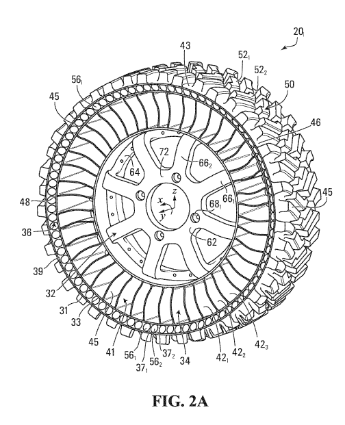
Figure 2A shows a perspective view of a wheel;
Figure 2B shows a close-up view of part of a non-pneumatic tire of the wheel;
Figure 3 shows a cross-sectional view of the wheel;
Figures 4 to 7 show representations of the wheel in different conditions;
5
CA 03006801 2018-05-29
WO 2017/106723
PCT/US2016/067289
Figure 8 shows an example of an embodiment in which a hub of the wheel is
resiliently
deform able;
Figures 9 and 10 show representations of the wheel of Figure 8 in different
conditions;
Figures 11 and 12 show charts that relate radial loading and deflection for
the wheel of
Figure 8;
Figure 13 shows deformed and undeformed states of the wheel of Figure 8 in
various
conditions;
Figure 14 shows a variant of the vehicle;
Figure 15 shows lateral loading on the wheels of the vehicle during a
maneuver;
Figure 16 shows a lateral load on the wheel;
Figure 17 shows a cornering load on the wheel;
Figure 18 shows an example of a test for determining a lateral stiffness of
the wheel;
Figures 19 to 21 show an example of an embodiment in which the wheel is
modular;
Figure 22 shows a plurality of different hubs to which the non-pneumatic tire
may be
fitted;
Figure 23 shows an attachment mechanism of the wheel of Figures 19 to 21;
Figure 24 shows an example of an embodiment in which the non-pneumatic tire
and the
hub are made integrally as one piece;
6
CA 03006801 2018-05-29
WO 2017/106723
PCT/US2016/067289
Figure 25 shows an example of an embodiment in which the wheel comprises a
damping mechanism;
Figure 26 shows an example of an embodiment in which the annular beam
comprises a
reinforcing layer;
Figure 27 shows an example of an embodiment of the reinforcing layer;
Figure 28 shows an example of another embodiment of the reinforcing layer;
lo
Figure 29 shows an example of an embodiment in which a thickness of the
annular
beam is increased;
Figure 30 shows an example of another vehicle comprising wheels in accordance
with
another embodiment of the invention;
Figure 31 shows a wheel of the vehicle of Figure 30; and
Figure 32 shows an example of another vehicle comprising wheels in accordance
with
another embodiment of the invention.
It is to be expressly understood that the description and drawings are only
for the
purpose of illustrating certain embodiments of the invention and are an aid
for
understanding. They are not intended to be a definition of the limits of the
invention.
DETAILED DESCRIPTION OF EMBODIMENTS
Figures 1A and 1B show an example of a vehicle 10 comprising wheels 201-204 in
accordance with an embodiment of the invention. In this embodiment, the
vehicle 10 is
an all-terrain vehicle (ATV). The ATV 10 is a small open vehicle designed to
travel off-
road on a variety of terrains, including roadless rugged terrain, for
recreational, utility
7
CA 03006801 2018-05-29
WO 2017/106723
PCT/US2016/067289
and/or other purposes. In this example, the ATV 10 comprises a frame 12, a
powertrain
14, a steering system 16, a suspension 18, the wheels 201-204, a seat 22, and
a user
interface 24, which enable a user of the ATV to ride the ATV 10 on the ground.
The ATV
has a longitudinal direction, a widthwise direction, and a height direction.
5
In this embodiment, as further discussed later, the wheels 201-204 are non-
pneumatic
(i.e., airless) and may be designed to enhance their use and performance
and/or use
and performance of the ATV 10, including, for example, to improve a shock-
absorbing
capability of the wheels 201-204, to improve a lateral stability of the ATV
10, and/or to
10 enhance other aspects of their use and performance and/or that of the
ATV 10.
The powertrain 14 is configured for generating motive power and transmitting
motive
power to respective ones of the wheels 201-204 to propel the ATV 10 on the
ground. To
that end, the powertrain 14 comprises a prime mover 26, which is a source of
motive
power that comprises one or more motors. For example, in this embodiment, the
prime
mover 26 comprises an internal combustion engine. In other embodiments, the
prime
mover 26 may comprise another type of motor (e.g., an electric motor) or a
combination
of different types of motor (e.g., an internal combustion engine and an
electric motor).
The prime mover 26 is in a driving relationship with one or more of the wheels
201-204.
That is, the powertrain 14 transmits motive power generated by the prime mover
26 to
one or more of the wheels 201-204 (e.g., via a transmission and/or a
differential) in order
to drive (i.e., impart motion to) these one or more of the wheels 201-204.
The steering system 16 is configured to enable the user to steer the ATV 10 on
the
ground. To that end, the steering system 16 comprises a steering device 28
that is
operable by the user to direct the ATV 10 along a desired course on the
ground. In this
embodiment, the steering device 28 comprises handlebars. The steering device
28 may
comprise a steering wheel or any other steering component that can be operated
by the
user to steer the ATV 10 in other embodiments. The steering system 16 responds
to the
user interacting with the steering device 28 by turning respective ones of the
wheels
201-204 to change their orientation relative to the frame 12 of the ATV 10 in
order to
8
CA 03006801 2018-05-29
WO 2017/106723
PCT/US2016/067289
cause the ATV 10 to move in a desired direction. In this example, front ones
of the
wheels 201-204 are turnable in response to input of the user at the steering
device 28 to
change their orientation relative to the frame 12 of the ATV 10 in order to
steer the ATV
on the ground. More particularly, in this example, each of the front ones of
the
5 wheels 201-204 is pivotable about a steering axis 30 of the ATV 10 in
response to input
of the user at the steering device 10 in order to steer the ATV 10 on the
ground. Rear
ones of the wheels 201-204 are not turned relative to the frame 12 of the ATV
10 by the
steering system 16.
10 The suspension 18 is connected between the frame 12 and the wheels 201-
204 to allow
relative motion between the frame 12 and the wheels 201-204 as the ATV 10
travels on
the ground. For example, the suspension 18 enhances handling of the ATV 10 on
the
ground by absorbing shocks and helping to maintain traction between the wheels
201-
204 and the ground. The suspension 18 may comprise an arrangement of springs
and
dampers. A spring may be a coil spring, a leaf spring, a gas spring (e.g., an
air spring),
or any other elastic object used to store mechanical energy. A damper (also
sometimes
referred to as a "shock absorber") may be a fluidic damper (e.g., a pneumatic
damper, a
hydraulic damper, etc.), a magnetic damper, or any other object which absorbs
or
dissipates kinetic energy to decrease oscillations. In some cases, a single
device may
itself constitute both a spring and a damper (e.g., a hydropneumatic,
hydrolastic, or
hydragas suspension device).
In this embodiment, the seat 22 is a straddle seat and the ATV 10 is usable by
a single
person such that the seat 22 accommodates only that person driving the ATV 10.
In
other embodiments, the seat 22 may be another type of seat, and/or the ATV 10
may be
usable by two individuals, namely one person driving the ATV 10 and a
passenger,
such that the seat 22 may accommodate both of these individuals (e.g., behind
one
another or side-by-side) or the ATV 10 may comprise an additional seat for the
passenger. For example, in other embodiments, the ATV 10 may be a side-by-side
ATV, sometimes referred to as a "utility terrain vehicle" or "utility task
vehicle" (UTV).
9
CA 03006801 2018-05-29
WO 2017/106723
PCT/US2016/067289
The user interface 24 allows the user to interact with the ATV 10. More
particularly, the
user interface 24 comprises an accelerator, a brake control, and the steering
device 28
that are operated by the user to control motion of the ATV 10 on the ground.
The user
interface 24 also comprises an instrument panel (e.g., a dashboard) which
provides
indicators (e.g., a speedometer indicator, a tachometer indicator, etc.) to
convey
information to the user.
The wheels 201-204 engage the ground to provide traction to the ATV 10. More
particularly, in this example, the front ones of the wheels 201-204 provide
front traction to
the ATV 10 while the rear ones of the wheels 201-204 provide rear traction to
the ATV
10.
Each wheel 20i comprises a non-pneumatic tire 34 for contacting the ground and
a hub
32 for connecting the wheel 20i to an axle 17 of the ATV 10. The non-pneumatic
tire 34
is a compliant wheel structure that is not supported by gas (e.g., air)
pressure and that
is resiliently deformable (i.e., changeable in configuration) as the wheel 20i
contacts the
ground.
With additional reference to Figures 2A to 5, the wheel 20i has an axial
direction defined
by an axis of rotation 35 of the wheel 20i (also referred to as a "Y"
direction), a radial
direction (also referred to as a "Z" direction), and a circumferential
direction (also
referred to as a "X" direction). The wheel 20i has an outer diameter Dw and a
width Ww.
It comprises an inboard lateral side 54 for facing a center of the ATV 10 in
the widthwise
direction of the ATV 10 and an outboard lateral side 49 opposite the inboard
lateral side
54. As shown in Figure 4, when it is in contact with the ground, the wheel 20i
has an
area of contact 25 with the ground, which may be referred to as a "contact
patch" of the
wheel 20i with the ground. The contact patch 25 of the wheel 20, which is a
contact
interface between the non-pneumatic tire 34 and the ground, has a dimension
Lc,
referred to as a "length", in the circumferential direction of the wheel 20i
and a
dimension Wc, referred to as a "width", in the axial direction of the wheel
20.
CA 03006801 2018-05-29
WO 2017/106723
PCT/US2016/067289
The non-pneumatic tire 34 comprises an annular beam 36 and an annular support
41
that is disposed between the annular beam 36 and the hub 32 of the wheel 20i
and
configured to support loading on the wheel 20i as the wheel 20i engages the
ground. In
this embodiment, the non-pneumatic tire 34 is tension-based such that the
annular
support 41 is configured to support the loading on the wheel 20i by tension.
That is,
under the loading on the wheel 20i, the annular support 41 is resiliently
deformable such
that a lower portion 27 of the annular support 41 between the axis of rotation
35 of the
wheel 20i and the contact patch 25 of the wheel 20i is compressed (e.g., with
little
reaction force vertically) and an upper portion 29 of the annular support 41
above the
axis of rotation 35 of the wheel 20i is in tension to support the loading.
The annular beam 36 of the tire 34 is configured to deflect under the loading
on the
wheel 20i at the contact patch 25 of the wheel 20i with the ground. For
instance, the
annular beam 36 functions like a beam in transverse deflection. An outer
peripheral
extent 46 of the annular beam 36 and an inner peripheral extent 48 of the
annular beam
36 deflect at the contact patch 25 of the wheel 20i under the loading on the
wheel 20i. In
this embodiment, the annular beam 36 is configured to deflect such that it
applies a
homogeneous contact pressure along the length Lc of the contact patch 25 of
the wheel
20i with the ground.
More particularly, in this embodiment, the annular beam 36 comprises a shear
band 39
configured to deflect predominantly by shearing at the contact patch 25 under
the
loading on the wheel 20i. That is, under the loading on the wheel 20i, the
shear band 39
deflects significantly more by shearing than by bending at the contact patch
25. The
shear band 39 is thus configured such that, at a center of the contact patch
25 of the
wheel 20i in the circumferential direction of the wheel 20i, a shear
deflection of the shear
band 39 is significantly greater than a bending deflection of the shear band
39. For
example, in some embodiments, at the center of the contact patch 25 of the
wheel 20i in
the circumferential direction of the wheel 20i, a ratio of the shear
deflection of the shear
band 39 over the bending deflection of the shear band 39 may be at least 1.2,
in some
cases at least 1.5, in some cases at least 2, in some cases at least 3, and in
some
11
CA 03006801 2018-05-29
WO 2017/106723
PCT/US2016/067289
cases even more (e.g., 4 or more). For instance, in some embodiments, the
annular
beam 36 may be designed based on principles discussed in U.S. Patent
Application
Publication 2014/0367007, which is hereby incorporated by reference herein, in
order to
achieve the homogeneous contact pressure along the length Lc of the contact
patch 25
of the wheel 20i with the ground.
In this example of implementation, the shear band 39 comprises an outer rim
31, an
inner rim 33, and a plurality of openings 561-56N between the outer rim 31 and
the inner
rim 33. The shear band 39 comprises a plurality of interconnecting members 371-
37p
that extend between the outer rim 31 and the inner rim 33 and are disposed
between
respective ones of the openings 561-56N. The interconnecting members 371-37p
may be
referred to as "webs" such that the shear band 39 may be viewed as being "web-
like" or
"webbing". The shear band 39, including the openings 561-56N and the
interconnecting
members 371-37p, may be arranged in any other suitable way in other
embodiments.
The openings 561-56N of the shear band 39 help the shear band 39 to deflect
predominantly by shearing at the contact patch 25 under the loading on the
wheel 20.
In this embodiment, the openings 561-56N extend from the inboard lateral side
54 to the
outboard lateral side 49 of the tire 34. That is, the openings 561-56N extend
laterally
though the shear band 39 in the axial direction of the wheel 20. The openings
561-56N
may extend laterally without reaching the inboard lateral side 54 and/or the
outboard
lateral side 49 of the tire 34 in other embodiments. The openings 561-56N may
have any
suitable shape. In this example, a cross-section of each of the openings 561-
56N is
circular. The cross-section of each of the openings 561-56N may be shaped
differently in
other examples (e.g., polygonal, partly curved and partly straight, etc.). In
some cases,
different ones of the openings 561-56N may have different shapes. In some
cases, the
cross-section of each of the openings 561-56N may vary in the axial direction
of the
wheel 20. For instance, in some embodiments, the openings 561-56N may be
tapered in
the axial direction of the wheel 20i such that their cross-section decreases
inwardly
axially (e.g., to help minimize debris accumulation within the openings 561-
56N).
12
CA 03006801 2018-05-29
WO 2017/106723
PCT/US2016/067289
In this embodiment, the tire 34 comprises a tread 50 for enhancing traction
between the
tire 34 and the ground. The tread 50 is disposed about the outer peripheral
extent 46 of
the annular beam 36, in this case about the outer rim 31 of the shear band 39.
More
particularly, in this example the tread 50 comprises a tread base 43 that is
at the outer
peripheral extent 46 of the annular beam 36 and a plurality of tread
projections 521-52T
that project from the tread base 52. The tread 50 may be implemented in any
other
suitable way in other embodiments (e.g., may comprise a plurality of tread
recesses,
etc.).
The annular support 41 is configured to support the loading on the wheel 20i
as the
wheel 20i engages the ground. As mentioned above, in this embodiment, the
annular
support 41 is configured to support the loading on the wheel 20i by tension.
More
particularly, in this embodiment, the annular support 41 comprises a plurality
of support
members 421-42T that are distributed around the tire 34 and resiliently
deformable such
that, under the loading on the wheel 20, lower ones of the support members 421-
42T in
the lower portion 27 of the annular support 41 (between the axis of rotation
35 of the
wheel 20i and the contact patch 25 of the wheel 20) are compressed and bend
while
upper ones of the support members 421-42T in the upper portion 29 of the
annular
support 41 (above the axis of rotation 35 of the wheel 20) are tensioned to
support the
loading. As they support load by tension when in the upper portion 29 of the
annular
support 41, the support members 421-42T may be referred to as "tensile"
members.
In this embodiment, the support members 421-42T are elongated and extend from
the
annular beam 36 towards the hub 32 generally in the radial direction of the
wheel 20. In
that sense, the support members 421-42T may be referred to as "spokes" and the
annular support 41 may be referred to as a "spoked" support.
More particularly, in this embodiment, the inner peripheral extent 48 of the
annular
beam 36 is an inner peripheral surface of the annular beam 36 and each spoke
42i
extends from the inner peripheral surface 48 of the annular beam 36 towards
the hub 32
generally in the radial direction of the wheel 20i and from a first lateral
end 55 to a
13
CA 03006801 2018-05-29
WO 2017/106723
PCT/US2016/067289
second lateral end 58 in the axial direction of the wheel 20. In this case,
the spoke 42i
extends in the axial direction of the wheel 20i for at least a majority of a
width WT of the
tire 34, which in this case corresponds to the width Ww of the wheel 20. For
instance, in
some embodiments, the spoke 42i may extend in the axial direction of the wheel
20i for
more than half, in some cases at least 60%, in some cases at least 80%, and in
some
cases an entirety of the width WT of the tire 34. Moreover, the spoke 42i has
a thickness
Ts measured between a first surface face 59 and a second surface face 61 of
the spoke
42i that is significantly less than a length and width of the spoke 42.
When the wheel 20i is in contact with the ground and bears a load (e.g., part
of a weight
of the ATV 10), respective ones of the spokes 421-42-r that are disposed in
the upper
portion 29 of the spoked support 41 (i.e., above the axis of rotation 35 of
the wheel 20)
are placed in tension while respective ones of the spokes 421-42-r that are
disposed in
the lower portion 27 of the spoked support 41 (i.e., adjacent the contact
patch 25) are
placed in compression. The spokes 421-42-r in the lower portion 27 of the
spoked
support 41 which are in compression bend in response to the load. Conversely,
the
spokes 421-42-r in the upper portion 29 of the spoked support 41 which are
placed in
tension support the load by tension.
The tire 34 has an inner diameter DTI and an outer diameter DTO, which in this
case
corresponds to the outer diameter Dw of the wheel 20. A sectional height HT of
the tire
34 is half of a difference between the outer diameter DTO and the inner
diameter DTI of
the tire 34. The sectional height HT of the tire may be significant in
relation to the width
WT of the tire 34. In other words, an aspect ratio AR of the tire 34
corresponding to the
sectional height HT over the width WT of the tire 34 may be relatively high.
For instance,
in some embodiments, the aspect ratio AR of the tire 34 may be at least 70%,
in some
cases at least 90%, in some cases at least 110%, and in some cases even more.
Also,
the inner diameter DTI of the tire 34 may be significantly less than the outer
diameter
DTO of the tire 34 as this may help for compliance of the wheel 20. For
example, in
some embodiments, the inner diameter DTI of the tire 34 may be no more than
half of
the outer diameter DTO of the tire 34, in some cases less than half of the
outer diameter
14
CA 03006801 2018-05-29
WO 2017/106723
PCT/US2016/067289
DTO of the tire 34, in some cases no more than 40% of the outer diameter DTO
of the tire
34, and in some cases even a smaller fraction of the outer diameter DTO of the
tire 34.
The hub 32 is disposed centrally of the tire 34 and connects the wheel 20i to
the axle 17
of the ATV 10. In this embodiment, the hub 32 comprises an inner member 62, an
outer
member 64 radially outward of the inner member 62, and a plurality of arms 661-
66A
joining the inner member 62 and the outer member 64. The inner member 62
comprises
apertures 681-68A defining a bolt pattern of the hub 32. The apertures 681-68A
allow a
user to locate therein wheel studs (i.e., threaded fasteners) that typically
project from a
brake disk or a brake drum of the ATV 10. A lug nut 75 can be used to secure
the hub
32 to each wheel stud in order to establish a fixed connection between the
wheel 20i
and the axle 17 of the ATV 10. The bolt pattern of the hub 32 (e.g., the
number and/or
positioning of apertures 681-68A in the inner member 62) may be designed in
any
suitable way (e.g., dependent on the type, model and/or brand of the ATV 10 to
which
the hub 32 is designed to fit). The hub 32 may be implemented in any other
suitable
manner in other embodiments (e.g., it may have any other suitable shape or
design).
The wheel 20i may be made up of one or more materials. The non-pneumatic tire
34
comprises a tire material 45 that makes up at least a substantial part (i.e.,
a substantial
part or an entirety) of the tire 34. The hub 32 comprises a hub material 72
that makes
up at least a substantial part of the hub 32. In some embodiments, the tire
material 45
and the hub material 72 may be different materials. In other embodiments, the
tire
material 45 and the hub material 72 may be a common material (i.e., the same
material).
In this embodiment, the tire material 45 constitutes at least part of the
annular beam 36
and at least part of the spokes 421-42T. Also, in this embodiment, the tire
material 45
constitutes at least part of the tread 50. More particularly, in this
embodiment, the tire
material 45 constitutes at least a majority (e.g., a majority or an entirety)
of the annular
beam 36, the tread 50, and the spokes 421-42T. In this example of
implementation, the
tire material 45 makes up an entirety of the tire 34, including the annular
beam 36, the
CA 03006801 2018-05-29
WO 2017/106723
PCT/US2016/067289
spokes 421-42-r, and the tread 50. The tire 34 is thus monolithically made of
the tire
material 45. In this example, therefore, the annular beam 36 is free of (i.e.,
without) a
substantially inextensible reinforcing layer running in the circumferential
direction of the
wheel 20i (e.g., a layer of metal, composite (e.g., carbon fibers, other
fibers), and/or
another material that is substantially inextensible running in the
circumferential direction
of the wheel 20i). In that sense, the annular beam 36 may be said to be
"unreinforced".
The tire material 45 is elastomeric. For example, in this embodiment, the tire
material 45
comprises a polyurethane (PU) elastomer. For instance, in some cases, the PU
elastomer may be composed of a TDI pre-polymer, such as PET-95A, cured with
MCDEA, commercially available from COIM. Other materials that may be suitable
include using PET95-A or PET60D, cured with MOCA. Other materials available
from
Chemtura may also be suitable. These may include Adiprene E500X and E615X
prepolymers, cured with C3LF or HQEE curative. Blends of the above prepolymers
are
also possible. Prepolymer C930 and C600, cured with C3LF or HQEE may also be
suitable, as are blends of these prepolymers.
Polyurethanes that are terminated using MDI or TDI are possible, with ether
and/or
ester and/or polycaprolactone formulations, in addition to other curatives
known in the
cast polyurethane industry. Other suitable resilient, elastomeric materials
would include
thermoplastic materials, such as HYTREL co-polymer, from DuPont, or
thermoplastic
polyurethanes such as Elastollan, from BASF. Materials in the 95A to 60D
hardness
level may be particularly useful, such as Hytrel 5556 and Elastollan 98A. Some
resilient
thermoplastics, such as plasticized nylon blends, may also be used. The Zytel
line of
nylons from DuPont may be particularly useful. The tire material 45 may be any
other
suitable material in other embodiments.
In this embodiment, the tire material 45 may exhibit a non-linear stress vs.
strain
behavior. For instance, the tire material 45 may have a secant modulus that
decreases
with increasing strain of the tire material 45. The tire material 45 may have
a high
Young's modulus that is significantly greater than the secant modulus at 100%
strain
16
CA 03006801 2018-05-29
WO 2017/106723
PCT/US2016/067289
(a.k.a. "the 100% modulus"). Such a non-linear behavior of the tire material
45 may
provide efficient load carrying during normal operation and enable impact
loading and
large local deflections without generating high stresses. For instance, the
tire material
45 may allow the tire 34 to operate at a low strain rate (e.g., 2% to 5%)
during normal
operation yet simultaneously allow large strains (e.g., when the ATV 10
engages
obstacles) without generating high stresses. This in turn may be helpful to
minimize
vehicle shock loading and enhance durability of the tire 34.
The tire 34 may comprise one or more additional materials in addition to the
tire material
45 in other embodiments (e.g., different parts of the annular beam 36,
different parts of
the tread 50, and/or different parts of the spokes 421-42T may be made of
different
materials). For example, in some embodiments, different parts of the annular
beam 36,
different parts of the tread 50, and/or different parts of the spokes 421-42T
may be made
of different elastomers. As another example, in some embodiments, the annular
beam
36 may comprise one or more substantially inextensible reinforcing layers
running in the
circumferential direction of the wheel 20i (e.g., one or more layers of metal,
composite
(e.g., carbon fibers, other fibers), and/or another material that is
substantially
inextensible running in the circumferential direction of the wheel 20i).
In this embodiment, the hub material 72 constitutes at least part of the inner
member
62, the outer member 64, and the arms 661-66A of the hub 32. More
particularly, in this
embodiment, the hub material 72 constitutes at least a majority (e.g., a
majority or an
entirety) of the inner member 62, the outer member 64, and the arms 661-66A.
In this
example of implementation, the hub material 72 makes up an entirety of the hub
32.
In this example of implementation, the hub material 72 is polymeric. More
particularly, in
this example of implementation, the hub material 72 is elastomeric. For
example, in this
embodiment, the hub material 72 comprises a polyurethane (PU) elastomer. For
instance, in some cases, the PU elastomer may be PET-95A commercially
available
from COIM, cured with MCDEA.
17
CA 03006801 2018-05-29
WO 2017/106723
PCT/US2016/067289
The hub material 72 may be any other suitable material in other embodiments.
For
example, in other embodiments, the hub material 72 may comprise a stiffer
polyurethane material, such as COIM's PET75D cured with MOCA. In some
embodiments, the hub material 72 may not be polymeric. For instance, in some
embodiments, the hub material 72 may be metallic (e.g., steel, aluminum,
etc.).
The hub 32 may comprise one or more additional materials in addition to the
hub
material 72 in other embodiments (e.g., different parts of the inner member
62, different
parts of the outer member 64, and/or different parts of the arms 661-66A may
be made
of different materials).
The wheel 20i may be manufactured in any suitable way. For example, in some
embodiments, the tire 34 and/or the hub 32 may be manufactured via centrifugal
casting, a.k.a. spin casting, which involves pouring one or more materials of
the wheel
20i into a mold that rotates about an axis. The material(s) is(are)
distributed within the
mold via a centrifugal force generated by the mold's rotation. In some cases,
vertical
spin casting, in which the mold's axis of rotation is generally vertical, may
be used. In
other cases, horizontal spin casting, in which the mold's axis of rotation is
generally
horizontal, may be used. The wheel 20i may be manufactured using any other
suitable
manufacturing processes in other embodiments.
The NPT wheel 20i may be lightweight. That is, a mass Mw of the wheel 20i may
be
relatively small. For example, in some embodiments, a ratio m
¨normalized Of the mass Mw
of the wheel 20i over the outer diameter Dw of the wheel 20i normalized by the
width
WW of the wheel 20i,
(1,k)
Mnormalized =
V VW
may be no more than 0.0005 kg/mm2, in some cases no more than 0.0004 kg/mm2,
in
some cases no more than 0.0003 kg/mm2, in some cases no more than 0.0002
kg/mm2,
in some cases no more than 0.00015 kg/mm2, in some cases no more than 0.00013
18
CA 03006801 2018-05-29
WO 2017/106723
PCT/US2016/067289
kg/mm2, in some cases no more than 0.00011 kg/mm2, and in some cases even less
(e.g., no more than 0.0001).
For instance, in some embodiments, the outer diameter of the wheel 20i may be
690
mm (27"), the width of the wheel 20i may be 230 mm (9"), and the mass Mw of
the
wheel 20i may be less than 25 kg, in some cases no more than 22 kg, in some
cases no
more than 20 kg, in some cases no more than 18 kg, in some cases no more than
16
kg, and in some cases even less.
The wheel 20, including the tire 34 and the hub 32, may have various features
to
enhance its use and performance and/or use and performance of the ATV 10,
including,
for example, radial compliance characteristics to improve its shock-absorbing
capability,
lateral stiffness characteristics to improve the lateral stability of the ATV
10, and/or other
features. This may be achieved in various ways in various embodiments,
examples of
which will now be discussed.
1. Enhanced radial compliance for shock absorption
In some embodiments, a radial compliance Cz of the wheel 20i may be
significant. That
is, a radial stiffness Kz of the wheel 20i may be relatively low for shock
absorption (e.g.,
ride quality). The radial stiffness Kz of the wheel 20i is a rigidity of the
wheel 20i in the
radial direction of the wheel 20, i.e., a resistance of the wheel 20i to
deformation in the
radial direction of the wheel 20i when loaded. The radial compliance Cz of the
wheel 20i
is the inverse of the radial stiffness Kz of the wheel 20i (i.e., Cz = 1/Kz).
For example, in some embodiments, a ratio Kz normalized of the radial
stiffness Kz of the
wheel 20i over the outer diameter Dw of the wheel 20i normalized by the width
Ww of
the wheel 20i
Kz
Dw
Kz normalized = -
Ww
19
CA 03006801 2018-05-29
WO 2017/106723
PCT/US2016/067289
may be between 0.0001 kgf/mm3 and 0.0002 kgf/mm3, where the radial stiffness
Kz of
the wheel 20i is taken at a design load FDESIGN of the wheel 20, i.e., a
normal load
expected to be encountered by the wheel 20i in use such that only the tire 34
deflects
by a normal deflection. A value of the Kz normalized below this range may
result in a tire
that has excessive deflection at the design load and therefore suffers in
impact
absorption, while a value of the Kz normalized above this range may result in
a tire suffering
in normal ride comfort, as its radial stiffness is too high. Herein, a force
or load may be
expressed in units of kilogram-force (kqf), but this can be converted into
other units of
force (e.g., Newtons).
The radial stiffness Kz of the wheel 20i may be evaluated in any suitable way
in various
embodiments.
For example, in some embodiments, the radial stiffness Kz of the wheel 20i may
be
gauged using a standard SAE J2704.
As another example, in some embodiments, the radial stiffness Kz of the wheel
20i may
be gauged by standing the wheel 20i upright on a flat hard surface and
applying a
downward vertical load Fz on the wheel 20i at the axis of rotation 35 of the
wheel 20i
(e.g., via the hub 32). The downward vertical load Fz causes the wheel 20i to
elastically
deform from its original configuration (shown in dotted lines) to a biased
configuration
(show in full lines) by a deflection Dz. The deflection Dz is equal to a
difference between
a height of the wheel 20i in its original configuration and the height of the
wheel 20i in its
biased configuration. The radial stiffness Kz of the wheel 20i is calculated
as the
downward vertical load Fz over the measured deflection Dz.
For instance, in some embodiments, the radial stiffness Kz of the wheel 20i
may be no
more than 15 kgf/mm, in some cases no more than 11 kgf/mm, in some cases no
more
than 8 kgf/mm, and in some cases even less.
20
CA 03006801 2018-05-29
WO 2017/106723
PCT/US2016/067289
The radial compliance Cz of the wheel 20i is provided at least by a radial
compliance Czt
of the non-pneumatic tire 34. For instance, in this embodiment, the spokes 421-
42T can
deflect significantly in the radial direction of the wheel 20i under the
loading on the
wheel 20. This may allow the wheel 20i to have a "pneumatic-like" zone of
operation,
which is characterized by relatively little strain in the tire 34 and
relatively lower radial
rigidity. In the pneumatic-like zone, the load from the contact patch to the
hub 32 occurs
primarily through tension in the spoked support 41 comprising the spokes 421-
42T.
For example, in some embodiments, a volume fraction Vfs of the spoked support
41
comprising the spokes 421-42T may be minimized. The volume fraction Vfs of the
spoked
support 41 refers to a ratio of a volume occupied by material of the spoked
support 41
(i.e., a collective volume of the spokes 421-42T) over a volume bounded by the
annular
beam 36 and the hub 32. A high value of the volume fraction Vfs increases the
amount
of material between the outer diameter DOT and the inner diameter DIT of the
tire 34,
whereas a low value of the volume fraction Vfs decreases the amount of
material
between the outer diameter DOT and the inner diameter DIT of the tire 34. At
very high
deflections, as shown in Figures 6, 7, 10, and 13, the spokes 421-42T begin to
self-
contact. This, then, enables load transfer from the ground to the hub 32 via
compression. Therefore, when the amount of material in the spoked support 41
is
minimized, the pneumatic-like zone of operation of the wheel 20i is maximized.
Thus,
while this may be counterintuitive, minimizing material in the spoked support
41 may be
beneficial to robustness of the wheel 20i in off-road use. Minimizing impact
loading may
be accomplished by maximizing the pneumatic-like zone, and this may be aided
by
minimizing the volume fraction Vfs of the spoked support 41.
For instance, in some embodiments, the volume fraction Vfs of the spoked
support 41
may be no more than 15%, in some cases no more than 12%, in some cases no more
than 10%, in some cases no more than 8%, in some cases no more than 6%, and in
some cases even less. For example, in some embodiments, the volume fraction
Vfs of
the spoked support 41 may be between 6% and 9%.
21
CA 03006801 2018-05-29
WO 2017/106723
PCT/US2016/067289
Figure 4 shows a finite element model in the XZ plane of a representation of
an
embodiment of the wheel 20i according to the invention. Figure 5 shows a
normal
operating condition. With the hub 32 fixed in the XZ plane, when loaded to the
design
load FDESIGN, the wheel 20i develops the contact patch 25, whose length Lc
corresponds
to a design contact patch length LDESIGN, and a radial deflection dZ-DESIGN.
These design
quantities represent a force, contact patch length, and deflection seen in
ordinary
vehicle operation. As shown, dZ-DESIGN is a small percentage of the diameter
Dw of the
wheel 20.
The ATV 10 may often encounter obstacles and absorb impacts. Obstacles can be
large rocks or tree stumps and the like. Impacts can also come from traversing
jumps,
or other maneuvers in which the ATV 10 leaves the ground, causing the
suspension 18
and the wheels 201-204 to be subjected to impact forces.
Figure 6 shows the wheel 20i responding to an impact. The impact force,
FIMPACT,
causes deflection dZ-IMPACT and results in the length Lc of the contact patch
25 to
become an impact contact path length LIMPACT. Due to the design of the NPT, dZ-
IMPACT
can be a significant fraction of the diameter Dw of the wheel 20. This may be
very
beneficial to off-road vehicle performance. The tire 34 represents un-sprung
mass; as
such, the speed with which it can deform is much faster than the speed with
which the
suspension 18 can displace the wheel 20, or the speed with which a center of
gravity of
the ATV 10 can change. Thus, the ability of the tire 34 to resiliently deform
as shown in
Figure 6 is a critical improvement in off-road vehicle behavior.
Figure 7 shows the wheel 20i being rolled over an obstacle. The obstacle is
essentially
fully enveloped by the annular beam 36, similar to the performance of an
inflated tire.
In some embodiments, the radial compliance Cz of the wheel 20i may not be
provided
solely by the radial compliance Czt of the tire 34, but rather may be provided
by the
radial compliance Czt of the tire 34 and a radial compliance Czn of the hub
32. That is, in
addition to the tire 34, the hub 32 may also be radially compliant.
22
CA 03006801 2018-05-29
WO 2017/106723
PCT/US2016/067289
For instance, in some embodiments, as shown in Figures 8 to 13, the hub 32 may
be
resiliently deformable such that, in response to a given load on the wheel 20,
the hub
32 deforms elastically from a neutral configuration (shown in Figures 8 and 9)
to a
biased configuration (shown in Figures 10 and 13). The hub 32 being
resiliently
deformable may be useful in concert with the non-pneumatic tire 34. For a
pneumatic
tire, this may not necessarily be the case, as the pneumatic tire/wheel
interface needs
to remain a secure pressure vessel. With an NPT, this constraint is relaxed,
and the
hub 32 can be resiliently deformable.
The hub 32 which is resiliently deformable allows the wheel 20i to undergo two
stages
of deflection: the pneumatic-like zone of operation and an "impact zone" of
operation.
As indicated above, the pneumatic-like zone is characterized by relatively
little strain in
the tire 34 and relatively lower radial rigidity. In this embodiment, in the
pneumatic-like
zone, the load from the contact patch 25 to the hub 32 occurs primarily
through tension
in the spoked support 41 comprising the spokes 421-42T. The impact zone is
characterized by higher stresses and higher radial stiffness. In this impact
zone,
additional load from the contact patch 25 to the hub 32 occurs through
compression of
the annular beam 36, the spoked support 41, and the hub 32.
Figure 9 shows the wheel 20i with the resiliently deformable hub 32 in a
normal design
condition. In this case, the resiliently deformable hub 32 does not deform;
rather, it acts
essentially like a rigid hub (e.g., a metallic hub).
Figure 10 shows the wheel 20i with the resiliently deformable hub 32 subjected
to an
impact load FIMPACT and a deflection dZ-IMPACT. Now, there is significant
additional
compliance and deformation, thanks to the resiliently deformable hub 32. Thus,
even
very large deflections, in which dZ-IMPACT is a larger percentage of the
diameter Dw of the
wheel 20, are possible.
23
CA 03006801 2018-05-29
WO 2017/106723
PCT/US2016/067289
The hub 32 may be designed in any suitable way to be radially compliant. For
instance,
in some embodiments, the hub 32 may be made integrally with the tire 34 and
comprise
a central member 262 and a plurality of arms 2661-266A projecting radially
outward from
the central member 262. Each arm 266i is continuous with the tire 34 such that
the tire
material 45 is continuous with the hub material 72. That is, the hub material
72 may be
elastomeric and the same as the tire material 45.
In this embodiment, unlike the arms 661-66A of the hub 32 described above, the
arms
2661-266A of the hub 32 do not project rectilinearly to the tire 34. Rather,
each arm 266i
is curved such that it deviates from a rectilinear path along the radial
direction of the
wheel 20. The curved shape of the arms 2661-266A may allow the arms 2661-266A
to
deform elastically in response to a downward vertical load applied on the
wheel 20. In
particular, the arms 2661-266A of the hub 232 behave in a similar manner to
the spokes
421-42T of the tire 34. Notably, the arms 2661-266A of the hub 232 may be
placed in
tension or in compression depending on their position. For instance, the arms
2661-266A
that are in a lower region of the hub 32 adjacent the contact patch 25 of the
wheel 20i
are placed in compression and bend under the applied load while the arms 2661-
266A
that are in an upper region of the hub 32 (i.e., above the axis of rotation 35
of the wheel
20) are placed in tension to support the applied load.
For example, in some embodiments, the pneumatic-like zone deflection may be at
least
25%, in some cases at least 30%, and in some cases at least 35% of the
diameter Dw
of the wheel 20i and/or the impact zone deflection may be at least 5%, in some
cases
8%, and in some cases at least 10% of the diameter Dw of the wheel 20.
For example, in some embodiments, for the wheel 20i of Figure 10 in which the
diameter Dw is 300 mm. a pneumatic zone deflection of 115 mm and an impact
zone
deflection of 20 mm may yield excellent on-vehicle performance for an NPT of
this size.
Figure 11 shows an example of a load vs. deflection plot for the FEA model
shown in
Figures 8, 9, and 10. The pneumatic-like zone and the impact zone are shown,
clearly
24
CA 03006801 2018-05-29
WO 2017/106723
PCT/US2016/067289
differentiated by the change in radial stiffness. In the pneumatic-like zone,
the radial
stiffness is about 12 kgf/mm, whereas in the impact zone, the radial stiffness
increases
to about 200 kgf/mm. Figure 12 shows the large amount of absorbed energy
developed
within each zone.
In Figure 11, the design load for the wheel 20i of 230 kgf is achieved at the
low
deflection of around 18 mm. Therefore, the design deflection is a small
fraction of
around 16% of the pneumatic-like zone. This may be advantageous to vehicle
comfort
and stability, as the amount of tire deflection available for use during
impacts is
maximized. In fact, this dual approach ¨ maximizing the pneumatic-like zone
distance
and minimizing the design deflection ¨ may give excellent performance.
In this embodiment, this may be partially accomplished thanks to two factors:
(1) a high
counter deflection stiffness and (2) a low volume fraction Vfs of the spoked
support 41
comprising the spokes 421-42T.
Figure 13 shows a superposition of the undeformed and deformed tire geometries
for
the loading condition of Figure 10. When the central section of the
resiliently deformable
hub 32 is fixed, as shown, and the tire is loaded, the whole wheel 20i
deforms. Load is
passed from the contact patch 25 to the hub 32 via tension in the spokes 421-
42T, as
the annular beam 36 is deflected upwards. As shown, the spokes 421-42T become
taunt when the tire is loaded, and the annular beam 36 is translated up by a
small
amount 13, known as the "counter deflection", in the region opposite the
contact patch
25. This counter deflection is parasitic. A high counter deflection reduces
the contact
patch length for a given load, and reduces the effective deflection of the
annular beam
36 in obstacle envelopment. For instance, in some embodiments, a maximum
counter
deflection for the wheel 20i may be about 6 mm to 11 mm, which is about 6% to
11% of
the pneumatic-like zone of operation of the NPT.
2. Enhanced lateral stiffness for lateral stability
CA 03006801 2018-05-29
WO 2017/106723
PCT/US2016/067289
In some embodiments, the wheel 20i may improve the lateral stability of the
ATV 10,
such as when the ATV 10 performs a maneuver (e.g., a lane change) or during
other
transient situations in which the wheel 20i is subject to lateral loading.
To that end, a lateral stiffness Ky of the wheel 20i may be relatively high.
The lateral
stiffness of the wheel 20i is a rigidity of the wheel 20i in the widthwise
direction of the
wheel 20, i.e., a resistance of the wheel 20i to deformation in the widthwise
direction of
the wheel 20i when loaded in the widthwise direction of the wheel 20. A
cornering
stiffness Ko of the wheel 20i may also be relatively high.
For instance, in some embodiments, the wheel 20i may yield better lateral
stability than
a pneumatic tire without sacrificing ride comfort. For instance, in some
cases, this may
be because the lateral stiffness of the wheel 20i and the cornering stiffness
of the wheel
20i can be decoupled from the radial stiffness and total radial energy
absorption of the
wheel 20.
Poor lateral stiffness and/or cornering stiffness could otherwise result in
vehicle terminal
oversteer, in which the rear of the ATV 10 could lose traction in a turn and
begin to yaw
uncontrollably. Then, if the center of gravity of the ATV 10 is high and/or if
other causes
are present, the ATV 10 could experience a roll-over event. Therefore, having
the lateral
stiffness and the cornering stiffness that are high may be useful.
For example, Figure 14 shows a variant of the ATV 10 which is a UTV that has a
cargo
area 51 in the rear of the ATV 10. For instance, in this example, the cargo
area 51 can
carry up to 450 kg, at vehicle speeds of up to 80 kph. Thus, there is a large
difference
in the per tire load at the rear axle, Fz REAR, when the cargo area 51 is
empty and when
it is full. Fz REAR can vary from 230 kg (unloaded) to 450 kg (loaded). This
may create
challenges for vehicle stability in a lane change maneuver.
An aerial view of a lane change maneuver is shown in Figure 15. At the
beginning of
the lane change, the ATV 10 must develop a large lateral force at the front
axle. After
26
CA 03006801 2018-05-29
WO 2017/106723
PCT/US2016/067289
the ATV 10 crosses into the adjoining lane, the driver reverses steering angle
to center
the vehicle in the lane. The vehicle yaw rapidly changes directions. Then,
quite
critically, the rear axle tires must develop sufficient cornering force to
"catch" the vehicle
after the lane change, and the rear axle tires must have sufficient lateral
stiffness to
support the lateral force.
With the ATV 10 in the unloaded state, such transient stability may be
challenging. With
no cargo, the initial vehicle yaw rate can be quite high; yet, the rear axle
tires are lightly
loaded. This may make it difficult for the rear axle tires to develop
sufficient force to
decelerate the vehicle yaw and stabilize the vehicle after the lane change is
executed.
Figure 16 illustrates the lateral stiffness Ky of the wheel 20. Here, the
wheel 20i is
loaded to a design load in the Z direction against a flat surface. Then, the
ground is
deflected in the Y direction, creating a lateral force Fy on the wheel 20i
which induces a
deflection DY of the wheel 20i in the lateral direction of the wheel 20. The
lateral
stiffness Ky of the wheel 20i is Fy / DY, in kgf / mm.
Figure 17 illustrates the cornering stiffness KO of the wheel 20. The
rectangular area is
the contact patch 25 of the wheel 20i as it travels in the X direction, with a
slip angle 8.
As it does so, a reaction moment Mz is created. This is the self-aligning
torque. A
reaction force FY is also created. This force is a cornering force. The
cornering stiffness
KO of the wheel 20i is FY / 8, in kgf / degree.
Therefore, in some embodiments, in contrast to the radial stiffness Kz of the
wheel 20i
which may be relatively low, the lateral stiffness Ky of the wheel 20i may be
relatively
high, notably due to the construction of the non-pneumatic tire 34. The
lateral stiffness
Ky of the wheel 20i may thus be considerably greater than the radial stiffness
Kz of the
wheel 20i in some embodiments.
For example, in some embodiments, a ratio Ky/Kz of the lateral stiffness Ky of
the wheel
20i over the radial stiffness Kz of the wheel 20i measured at the rear axle
load of the
27
CA 03006801 2018-05-29
WO 2017/106723
PCT/US2016/067289
ATV 10 with no cargo may be at least 1.6, in some cases at least 1.8, in some
cases at
least 2, and in some cases even more. The ratio Ky/Kz may have any other
suitable
value in other embodiments.
The lateral stiffness Ky of the wheel 20i may be evaluated in any suitable way
in various
embodiments.
For instance, in one example, the lateral stiffness Ky of the wheel 20i may be
gauged
using a standard SAE J2718 test.
lo
In another example, as shown in Figure 18, the lateral stiffness Ky of the
wheel 20i may
be gauged by setting the wheel 204 such that the inboard lateral side 54 of
the tire 34
rcsts against a flat surfacc and applying a lateral load Fy on a given one of
the outboard
lateral side 49 and the inboard lateral side 54 of the tire 34. The lateral
load Fy causes
the wheel 20, notably the tire 34, to elastically deform from its original
configuration
(shown in dotted lines) to a biased configuration (shown in full lines) by a
deflection Dy
in the lateral direction of the wheel 20. Thc dcflcction D =
= - -. -
bctwccn thc width NAIT of thc tirc 34 in thc original configuration of thc
tirc 34 mc\asurcd
at a point of application of the load Fy-an-d-the-wielth-kth of the tire 34 in
the biased
configuration of the tire 34 measured at the point of application of the load
FyThe
lateral stiffness of the wheel 20i is calculated as the lateral load Fy over
the measured
lateral deflection Dy of the wheel 20.
For example, in some embodiments, the lateral stiffness Ky of the wheel 20i
may be at
least 15 kgf/mm, in some cases at least 20 kgf/mm, in some cases at least 30
kgf/mm,
and in some cases even more.
The cornering stiffness KO of the wheel 20i may also be relatively high,
notably due to
the construction of the non-pneumatic tire 34.
28
CA 03006801 2018-05-29
WO 2017/106723
PCT/US2016/067289
For instance, in some embodiments, a ratio Ko/Fz of the cornering stiffness KO
of the
wheel 20i at one degree over the rear axle load F7 of the ATV 10 with no cargo
may be
at least 0.2, in some cases at least 0.3, in some cases at least 0.4 and in
some cases
even more. The ratio Ko/Fz may have any other suitable value in other
embodiments.
The cornering stiffness KO of the wheel 20i may be evaluated in any suitable
way in
various embodiments.
For instance, in one example, the cornering stiffness KO of the wheel 20i may
be gauged
by measurement on an industry standard Flat-Trac machine, such as that used by
Smithers Rapra Corporation.
For example, in some embodiments, the cornering stiffness KO of the wheel 20,
when
measured at a design load, may be at least 40 kgf/deg, in some cases at least
60
kgf/deg, in some cases at least 80 kgf/deg, and in some cases even more.
The lateral stiffness Ky and the cornering stiffness KO of the wheel 20i may
be achieved
in any suitable way.
For example, in some embodiments, a width Ws of the spoked support 41
comprising
the spokes 421-42T may be significant in relation to the width WT of the tire
34. For
instance, in some embodiments, a ratio of the width Ws of the spoked support
41 over
the width WT of the tire 34 may be at least 0.7, in some cases at least 0.8,
in some
cases at least 0.9, and in some cases even more. For example, in some cases,
the
spoked support 41 may extend substantially completely across the annular beam
36 in
the axial direction of the wheel 20.
Other design attributes may also increase the lateral stiffness Ky and the
cornering
stiffness KO of the wheel 20. For example, in some embodiments, a stiffness of
the
annular beam 36 in the circumferential direction may increase the lateral
stiffness Ky of
the wheel 20. Increasing a stiffness of the spoked support 41, via an increase
in
29
CA 03006801 2018-05-29
WO 2017/106723
PCT/US2016/067289
material modulus of elasticity, may increase the lateral stiffness Ky of the
wheel 20.
Adding reinforcement materials, such as short or long fiber reinforcements,
may also
increase the lateral stiffness Ky of the wheel 20.
The enhanced radial compliance Cz (or, inversely, radial stiffness Kz) and the
enhanced
lateral stiffness Ky of the wheel 20i as discussed above in sections 1 and 2
may be
particularly useful with the wheel 20i being lightweight, such as where the
mass Mw of
the wheel 20, including a mass MT of the non-pneumatic tire 34, may be
relatively low
as discussed above.
lo
Also, the enhanced radial compliance Cz (or, inversely, radial stiffness Kz)
and the
enhanced lateral stiffness Ky of the wheel 20i as discussed above in sections
1 and 2
may be particularly useful as the ATV 10 travels fast, such as at a speed of
at least 50
km/h, in some cases at least 70 km/h, in some cases at least 90 km/h, and in
some
cases even faster.
3. Modular wheel
In some embodiments, as shown in Figures 19 to 21, the wheel 20i may be
modular in
that it may comprise a plurality of modules 671-67c that are assembled and
connected
to one another. For instance, in some embodiments, respective ones of the
modules
671-67c may be detachably connected to one another (i.e., separate components
that
can be selectively attached to and detached from one another). One or more of
the
modules 671-67c may be selected from a set of different modules and/or
replaceable by
a different module. This may be beneficial to allow the wheel 20i to be
adapted to a
variety of different ATVs.
In this embodiment, a module 671 comprises the non-pneumatic tire 34 and a
module
672 comprises the hub 32. More particularly, in this embodiment, the hub 32
may be
selected from a set of different hubs and/or replaceable by a different hub.
Examples of
different hubs 1321-132H having different characteristics (e.g., different
bolt patterns) are
CA 03006801 2018-05-29
WO 2017/106723
PCT/US2016/067289
illustrated in Figure 22. This may allow the wheel 20i to accommodate
different ATVs
which may require different configurations of the hub 32 (e.g., different bolt
patterns).
More particularly, in this embodiment, the tire 34 and the hub 32 are
detachably
connected to one another (i.e., they are selectively attachable to and
detachable from
one another). The wheel 20i comprises an attachment mechanism 70 for
connecting the
tire 34 and the hub 32. The attachment mechanism 70 comprises a connector 71
that is
part of the hub 32 and a connector 73 that is part of the tire 34 and
connectable to the
connector 71 of the hub 32. More particularly, in this embodiment, the
connector 71
comprises the outer member 64 of the hub 32 and the connector 73 comprises a
flange
74 projecting inwardly from an inner annular member 38 of the tire 34 from
which the
spokes 421-42T extend radially outwardly.
The flange 74 of the tire 34 comprises an inboard surface 78 facing the
inboard lateral
side 54 of the tire 34 and an outboard surface 80 facing the outboard lateral
side 49 of
the tire 34. The flange 74 is positioned such that a distance Li measured
between the
inboard surface 78 and an inboard lateral end 82 of the inner annular member
38
adjacent the inboard lateral side 54 of the tire 34 is greater than half the
distance L2
which is the total lateral distance of the inboard surface 40 from outboard
lateral end 84
to the inboard lateral end 82. For instance, a ratio Li/L2 may be at least
0.5, in some
cases at least 0.7, in some cases may approach 1. This positioning of the
flange 74
may allow the hub 32 to be spaced from the axle 17 and/or brake mechanism of
the
ATV 10 that is housed within a space defined by an inner peripheral surface 40
of the
inner annular member 38 when the wheel 20i is mounted to the ATV 10 such that
the
hub 32 does not contact the axle 17 and/or brake mechanism of the ATV 10.
In this embodiment, the outer member 64 of the hub 32 comprises a plurality of
holes
861-86H that traverse the outer member 64 and the flange 74 of the tire 34
comprises a
plurality of holes 961-96H that traverse the flange 74. The holes 861-86H, 961-
96H are
configured such that when the hub 32 is disposed on the tire 34, each hole 86i
can be
aligned with a corresponding hole 96.
31
CA 03006801 2018-05-29
WO 2017/106723
PCT/US2016/067289
In order to connect the tire 34 to the hub 32, the hub 32 is disposed on the
flange 74 to
bring the outer member 64 of the hub 32 into contact with the outboard lateral
surface
80 of the flange 74 of the tire 34. The holes 861-86H of the hub 32 are then
aligned with
the holes 961-96H of the flange 74. In this embodiment, the attachment
mechanism 70
further comprises a plurality of fastening elements 761-76F (e.g., bolts) to
secure to the
outer member 64 to the flange 74. As shown in Figure 23, each fastening
element 76i is
inserted into a holes 86i of the outer member 64 of the hub 32 and into a hole
96i of the
flange 74 of the tire 34 and is secured accordingly via a corresponding
fastening
element 77i (e.g., a nut). In some embodiments, a clamping plate may be
provided
between a head of the fastening element 76i and the outer member 64 to
distribute the
force applied by the fastening elements 76i on the outer member 64 and the
flange 74.
The attachment mechanism 70 may be implemented in any other suitable way in
other
embodiments (e.g., different types of fasteners, a quick-connect system,
etc.).
Instead of being distinct modules, as shown in Figure 24 and as discussed and
shown
in previous examples of implementation considered above, in some embodiments,
the
hub 32 and the tire 34 of the wheel 20i may be a single-piece construction
(i.e.,
integrally formed with one another as one piece). Thus, in some embodiments,
the
wheel 20i may consist of a single-piece construction. In such embodiments, the
tire
material 45 and the hub material 72 may be the same material or may be
different
materials (e.g., by introducing different materials at different times during
spin casting).
4. Different energy absorption properties
In some embodiments, the wheel 20i may have different energy absorption
properties
than that imparted by the compliance of the tire 34 and/or the hub 32. For
instance,
while the radial compliance of the wheel 20i imparts the wheel 20i with spring-
like
energy absorption properties, in some embodiments, the wheel 20i may also
include
energy damping properties. That is, the wheel 20i may have damping properties
that
32
CA 03006801 2018-05-29
WO 2017/106723
PCT/US2016/067289
allow the wheel 20i to dissipate energy. For instance, in some embodiments,
the wheel
20i may comprise a damping mechanism 90 for providing energy damping
properties to
the wheel 20. The damping mechanism 90 of the wheel 20i may be implemented in
various ways.
With additional reference to Figure 25, in one example of implementation, the
damping
mechanism 90 is comprised by the tire 34 and comprises a plurality of damping
elements 921-92D that are disposed on the inner annular member 38 of the tire
34 and
projecting radially outwardly therefrom. More particularly, the damping
elements 921-92D
are positioned between adjacent ones of the spokes 421-42T. The damping
elements
921-92D can be affixed to inner annular member 38 in any suitable way. For
instance, in
this example, the damping elements 921-92D are fastened to the inner annular
member
38 via fasteners (e.g., bolts, screws, etc.).
Each damping element 92i comprises a damping material 94 that dissipates
energy
when impacted. For example, in this embodiment, the damping material 94 is
rubber.
The damping material 94 of the damping element 92i may be any other suitable
material
in other embodiments.
In use, when the wheel 20i deforms radially in response to a load, the annular
beam 36
at the contact patch 25 may contact one or more the damping elements 921-92D
or may
cause certain spokes 421-42T to contact one or more of the damping elements
921-92D.
This contact with the damping elements 921-92D transfers the load that would
otherwise
be absorbed by the compliance of the tire 34 to the damping elements 921-92D.
Due to
their damping properties, the damping elements 921-92D dissipate the energy
from such
an impact.
The damping mechanism 90 may be configured in any other suitable way in other
embodiments.
5. Reinforced annular beam
33
CA 03006801 2018-05-29
WO 2017/106723
PCT/US2016/067289
In some embodiments, the annular beam 36 may comprise one or more reinforcing
layers running in the circumferential direction of the wheel 20i to reinforce
the annular
beam 36, such as one or more substantially inextensible reinforcing layers
running in
the circumferential direction of the wheel 20i (e.g., one or more layers of
metal,
composite (e.g., carbon fibers, other fibers), and/or another material that is
substantially
inextensible running in the circumferential direction of the wheel 20i). For
instance, this
may reinforce the annular beam 36 by protecting it against cracking and/or by
better
managing heat generated within it as it deforms in use.
For example, in some embodiments, as shown in Figure 26, the annular beam 36
may
comprise a reinforcing layer 47 running in the circumferential direction of
the wheel 20i
The reinforcing layer 47 is unnecessary for the annular beam 36 to deflect
predominantly by shearing, i.e., unnecessary for the shear band 39 to deflect
significantly more by shearing than by bending at the contact patch 25 of the
wheel 20i.
That is, the annular beam 36 would deflect predominantly by shearing even
without the
reinforcing layer 47. In other words, the annular beam 36 would deflect
predominantly
by shearing if it lacked the reinforcing layer 47 but was otherwise identical.
Notably, in
this embodiment, this is due to the openings 561-56N and the interconnecting
members
371-37p of the shear band 39 that facilitate deflection predominantly by
shearing.
The annular beam 36 has the reinforcing layer 47 but is free of any equivalent
reinforcing layer running in the circumferential direction of the wheel 20i
and spaced
from the reinforcing layer 47 in the radial direction of the wheel 20i. That
is, the annular
beam 36 has no reinforcing layer that is equivalent, i.e., identical or
similar in function
and purpose, to the reinforcing layer 47 and spaced from the reinforcing layer
47 in the
radial direction of the wheel 20i. The annular beam 36 therefore lacks any
reinforcing
layer that is comparably stiff to (e.g., within 10% of a stiffness of) the
reinforcing layer 47
in the circumferential direction of the wheel 20i and spaced from the
reinforcing layer 47
in the radial direction of the wheel 20.
34
CA 03006801 2018-05-29
WO 2017/106723
PCT/US2016/067289
In this embodiment, the annular beam 36 has the reinforcing layer 47 but is
free of any
substantially inextensible reinforcing layer running in the circumferential
direction of the
wheel 20i and spaced from the reinforcing layer 47 in the radial direction of
the wheel
20. Thus, the reinforcing layer 47 is a sole reinforcing layer of the annular
beam 36.
More particularly, in this embodiment, the annular beam 36 has the reinforcing
layer 47
located on a given side of a neutral axis 57 of the annular beam 36 and is
free of any
substantially inextensible reinforcing layer running in the circumferential
direction of the
wheel 20i on an opposite side of the neutral axis 57 of the annular beam 36.
That is, the
reinforcing layer 47 is located between the neutral axis 57 of the annular
beam 36 and a
given one of the inner peripheral extent 48 and the outer peripheral extent 46
of the
annular beam 36 in the radial direction of the wheel 20, while the annular
beam 36 is
free of any substantially inextensible reinforcing layer running in the
circumferential
direction of the wheel 20i between the neutral axis 57 of the annular beam 36
and the
other one of the inner peripheral extent 48 and the outer peripheral extent 46
of the
annular beam 36 in the radial direction of the wheel 20.
The neutral axis 57 of the annular beam 36 is an axis of a cross-section of
the annular
beam 36 where there is substantially no tensile or compressive stress in the
circumferential direction of the wheel 20i when the annular beam 36 deflects
at the
contact patch 25 of the wheel 20. In this example, the neutral axis 57 is
offset from a
midpoint of the annular beam 36 between the inner peripheral extent 48 and the
outer
peripheral extent 46 of the annular beam 36 in the radial direction of the
wheel 20. More
particularly, in this example, the neutral axis 57 is closer to a given one of
the inner
peripheral extent 48 and the outer peripheral extent 46 of the annular beam 36
than to
an opposite one of the inner peripheral extent 48 and the outer peripheral
extent 46 of
the annular beam 36 in the radial direction of the wheel 20.
In this embodiment, the reinforcing layer 47 is disposed radially inwardly of
the neutral
axis 57 of the annular beam 36, and the annular beam 36 is free of any
substantially
CA 03006801 2018-05-29
WO 2017/106723
PCT/US2016/067289
inextensible reinforcing layer running in the circumferential direction of the
wheel 20i
radially outwardly of the neutral axis 57 of the annular beam 36.
In this example, the reinforcing layer 47 is disposed between the inner
peripheral extent
48 of the annular beam 36 and the openings 561-56N in the radial direction of
the wheel
20i, while the annular beam 36 is free of any substantially inextensible
reinforcing layer
running in the circumferential direction of the wheel 20i between the outer
peripheral
extent 46 of the annular beam 36 and the openings 561-56N in the radial
direction of the
wheel 20i.
lo
The reinforcing layer 47 may be implemented in any suitable way in various
embodiments.
For example, in some embodiments, as shown in Figure 27, the reinforcing layer
47
may include a layer of elongate reinforcing elements 621-62E that reinforce
the annular
beam 36 in one or more directions in which they are elongated, such as the
circumferential direction of the wheel 20i and/or one or more directions
transversal
thereto.
For instance, in some embodiments, the elongate reinforcing elements 621-62E
of the
reinforcing layer 47 may include reinforcing cables 631-63c that are adjacent
and
generally parallel to one another. For instance, the reinforcing cables 631-
63c may
extend in the circumferential direction of the wheel 20i to enhance strength
in tension of
the annular beam 36 along the circumferential direction of the wheel 20i. In
some cases,
a reinforcing cable may be a cord or wire rope including a plurality of
strands or wires. In
other cases, a reinforcing cable may be another type of cable and may be made
of any
material suitably flexible longitudinally (e.g., fibers or wires of metal,
plastic or composite
material).
In some embodiments, the elongate reinforcing elements 621-62E of the
reinforcing
layer 47 may include constitute a layer of reinforcing fabric 65. Reinforcing
fabric
36
CA 03006801 2018-05-29
WO 2017/106723
PCT/US2016/067289
comprises pliable material made usually by weaving, felting, knitting,
interlacing, or
otherwise crossing natural or synthetic elongated fabric elements, such as
fibers,
filaments, strands and/or others. For instance, as one example, in some
embodiments
such as that of Figure 27, the elongate reinforcing elements 621-62E of the
reinforcing
layer 47 that include the reinforcing cables 631-63c may also include
transversal fabric
elements 731-73T that extend transversally (e.g., perpendicularly) to and
interconnect
the reinforcing cables 631-63c. Thus, in this example, the reinforcing layer
47, including
its reinforcing cables 631-63c and its transversal fabric elements 731-73T,
can be viewed
as a reinforcing fabric or mesh (e.g., a "tire cord" fabric or mesh). As
another example,
in some embodiments, as shown in Figure 28, the reinforcing fabric 47 may
include
textile 75 (e.g., woven or nonwoven textile).
In other examples of implementation, the reinforcing layer 47 may include a
reinforcing
sheet (e.g., a thin, continuous layer of metallic material, such as steel or
aluminum that
extends circumferentially).
The reinforcing layer 47 may be made of one or more suitable materials. A
material 77
of the reinforcing layer 47 may be stiffer and stronger than the elastomeric
material 45
of the annular beam 36 in which it is disposed. For instance, in some
embodiments, the
material 77 of the reinforcing layer 47 may be a metallic material (e.g.,
steel, aluminum,
etc.). In other embodiments, the material 77 of the reinforcing layer 47 may
be a stiff
polymeric material, a composite material (e.g., a fiber-reinforced composite
material),
etc.
In this example of implementation, the reinforcing layer 47 comprises the
reinforcing
mesh or fabric that includes the reinforcing cables 631-63c and the
transversal fabric
elements 731-73T which are respectively 3 strands of steel wire of 0.28 mm
diameter,
wrapped together to form a cable, and high tenacity nylon cord of 1400x2.
In some embodiments, the reinforcing layer 47 may allow the elastomeric
material 45
(e.g.. PU) of the annular beam 36 to be less stiff, and this may facilitate
processability in
37
CA 03006801 2018-05-29
WO 2017/106723
PCT/US2016/067289
manufacturing the tire 34. For example, in some embodiments, the modulus of
elasticity
(e.g., Young's modulus) of the elastomeric material 45 of the annular beam 36
may be
no more than 200 MPa, in some cases no more than 150 MPa, in some cases no
more
than 100 MPa, in some cases no more than 50 MPa, and in some cases even less.
The reinforcing layer 47 may be provided in the annular beam 36 in any
suitable way. In
this embodiment, the reinforcing layer 47 may be formed as a hoop and placed
in the
mold before the elastomeric material 45 of the tire 34 is introduced in the
mold. As the
elastomeric material 45 is distributed within the mold via the centrifugal
force generated
by the mold's rotation, the reinforcing layer 47 is embedded in that portion
of the
elastomeric material 45 that forms the annular beam 36.
The reinforcing layer 47 may provide various benefits to the wheel 20i in
various
embodiments.
For example, in this embodiment, the reinforcing layer 47 may help to protect
the
annular beam 36 against cracking. More particularly, in this embodiment, as it
reinforces
the annular beam 36 proximate to the inner peripheral extent 48 of the annular
beam 36
that experiences tensile stresses when the annular beam 36 deflects in use,
the
reinforcing layer 47 may help the annular beam 36 to better withstand these
tensile
stresses that could otherwise increase potential for cracking to occur in the
elastomeric
material 45 of the annular beam 36.
As another example, in this embodiment, the reinforcing layer 47 may help to
better
manage heat generated within the annular beam 36 as it deforms in use. A
thermal
conductivity of the material 77 of the reinforcing layer 47 may be greater
than a thermal
conductivity of the elastomeric material 45 of the annular beam 36, such that
the
reinforcing layer 47 can better conduct and distribute heat generated within
the tire 34
as it deforms in use. This may allow a highest temperature of the elastomeric
material
45 to remain lower and therefore allow the wheel 20i to remain cooler and/or
run faster
at a given load than if the reinforcing layer 47 was omitted.
38
CA 03006801 2018-05-29
WO 2017/106723
PCT/US2016/067289
More particularly, in this embodiment, a ratio of the thermal conductivity of
the material
77 of the reinforcing layer 47 over the thermal conductivity of the
elastomeric material
45 of the annular beam 36 may be at least 50, in some cases at least 75, in
some cases
at least 100, and in some cases even more. For instance, in some embodiments,
the
thermal conductivity of the material 77 of the reinforcing layer 47 may be at
least 10
W/m/ C, in some cases at least 20 W/m/ C, in some cases at least 30 W/m/ C, in
some
cases at least 40 W/m/ C, and in some cases even more.
A thermal conductivity of a unidirectional composite layer can be calculated
by the
following equation:
Ki = + (1 ¨ Vc)Km (10)
Where: Ki = thermal conductivity of the ply in direction i
Vc = cable volume fraction in direction i
Kc = cable thermal conductivity
Km = matrix thermal conductivity
From Equation (10) the thermal conductivity of a composite is orthotropic;
i.e., it is
different in different directions. The tire designer can thus tune the
composite layer to
have the desired conductivity in the circumferential direction (say, the "1"
direction)
independently of the lateral direction (say, the "2") direction.
Most elastomers, such as rubber and polyurethane, are good thermal insulators.
The
inventors have found that even a fairly low cable volume fraction is
sufficient to raise the
thermal conductivity to a level that adequately evacuates heat. With a steel
cable,
Equation (10) shows that a cable volume fraction of 0.10 gives a composite
layer
thermal conductivity of 5.2 W/m/ C. This value, or even a value as low as 2.0
W/m/ C
may be sufficient to improve thermal performance.
In some embodiments, steel may be used as the reinforcing material in both the
circumferential and lateral directions. For example, to better dissipate heat
and
homogenize temperature, a steel cable of 3 strands of 0.28 mm diameter at a
pace of
39
CA 03006801 2018-05-29
WO 2017/106723
PCT/US2016/067289
1.8 mm could be used in both the vertical and lateral directions. Such a
composite layer
has an average thickness of about 1.0 mm, and a steel volume fraction of about
0.10 in
both vertical and lateral directions. As previously stated, this yields a
thermal
conductivity of about 5.2 W/m/ C for the composite layer.
In some embodiments, in addition to or instead of including the reinforcing
layer 47, as
shown in Figure 29, a thickness Tb of the annular beam 36 in the radial
direction of the
wheel 20i may be increased in order to reinforce the annular beam 36. More
particularly,
in this embodiment, the inner rim 33 may be increased in thickness. For
instance, the
inner rim 33 of the annular beam 36 may be thicker than the outer rim 31 of
the annular
beam 36 in the radial direction of the wheel 20. This may help the annular
beam 36 to
better withstand tensile stresses proximate to the inner peripheral extent 48
of the
annular beam 36 when the annular beam 36 deflects in use.
For example, in this embodiment, a ratio of a thickness Tb of the annular beam
36 in the
radial direction of the wheel 20i over the outer diameter Dw of the wheel 20i
may be at
least 0.05, in some cases at least 0.07, in some cases as least 0.09, and in
some cases
even more.
As another example, in this embodiment, a ratio of a thickness Tib of the
inner rim 33 of
the annular beam 36 in the radial direction of the wheel 20i over a thickness
Tob of the
outer rim 31 of the annular beam 36 in the radial direction of the wheel 20i
may be at
least 1.2, in some cases at least 1.4, in some cases as least 1.6, and in some
cases
even more.
While in embodiments considered above the wheel 20i is part of the ATV 10, a
wheel
constructed according to principles discussed herein may be used as part of
other
vehicles or other devices in other embodiments.
For example, with additional reference to Figures 30 and 31, in some
embodiments, an
industrial vehicle 210 may comprise wheels 2201-2204 constructed according to
CA 03006801 2018-05-29
WO 2017/106723
PCT/US2016/067289
principles discussed herein in respect of the wheel 20. The industrial vehicle
210 is a
heavy-duty vehicle designed to travel off-road to perform industrial work
using a work
implement 298. In this embodiment, the industrial vehicle 210 is a
construction vehicle.
More particularly, in this embodiment, the construction vehicle 210 is a
loader (e.g., a
skid-steer loader). The construction vehicle 210 may be a bulldozer, a backhoe
loader,
an excavator, a dump truck, or any other type of construction vehicle in other
embodiments.
The construction vehicle 210 comprises a frame 212, a powertrain 214, the
wheels
2201-2204, the work implement 298, and an operator cabin 284, which enable an
operator to move the construction vehicle 210 on the ground and perform
construction
work using the work implement 298. The operator cabin 284 is where the
operator sits
and controls the construction vehicle 210. More particularly, the operator
cabin 284
comprises a user interface that allows the operator to steer the construction
vehicle 210
on the ground and perform construction work using the working implement 298.
The working implement 298 is used to perform construction work. In this
embodiment
where the construction vehicle 210 is a loader, the working implement 298 is a
dozer
blade that can be used to push objects and shove soil, debris or other
material. In other
embodiments, depending on the type of construction vehicle, the working
implement
298 may be a backhoe, a bucket, a fork, a grapple, a scraper pan, an auger, a
saw, a
ripper, a material handling arm, or any other type of construction working
implement.
Each wheel 2201 of the construction vehicle 210 may be constructed according
to
principles described herein in respect of the wheels 201-204, notably by
comprising a
non-pneumatic tire 234 and a hub 232 that may be constructed according to
principles
described herein in respect of the non-pneumatic tire 34 and the hub 32. The
non-
pneumatic tire 234 comprises an annular beam 236 and an annular support 241
that
may be constructed according principles described herein in respect of the
annular
beam 36 and the annular support 41. For instance, the annular beam 236
comprises a
shear band 239 comprising openings 2561-256B and the annular support 41
comprises
41
CA 03006801 2018-05-29
WO 2017/106723
PCT/US2016/067289
spokes 2421-242j that may be constructed according to principles described
herein in
respect of the shear band 39 and the spokes 421-42-r. In this embodiment, the
shear
band 239 comprises intermediate rims 251, 253 between an outer rim 231 and an
inner
rim 233 such that the openings 2561-256N and interconnecting members 2371-237p
are
arranged into three circumferential rows between adjacent ones of the rims
231, 251,
253, 233.
Figure 31 shows an example of a finite element model of the wheel 220, which
in this
case is an equivalent of a 20.5 x 25 pneumatic tire used in the construction
industry.
The wheel 220i is 1.53 meters in diameter, 0.5 meters in width, and carries a
design
load of 10 metric tons (10,000 kgf). In this embodiment, an inner diameter of
the non-
pneumatic tire 34 is 0.62 meters. Like the wheel 20i described above, in this
embodiment, a pneumatic-like zone of deflection is greater than 37% of the
wheel's
diameter, and a volume fraction Vfs of the annular support 241 of the tire 234
is less
than about 9%.
As another example, in some embodiments, with additional reference to Figure
32, a
motorcycle 410 may comprise a front wheel 4201 and a rear wheel 4202
constructed
according to principles discussed herein in respect of the wheel 20.
As another example, in some embodiments, a wheel constructed according to
principles
discussed herein in respect of the wheel 20i may be used as part of an
agricultural
vehicle (e.g., a tractor, a harvester, etc.), a forestry vehicle, a material-
handling vehicle,
or a military vehicle.
As another example, in some embodiments, a wheel constructed according to
principles
discussed herein in respect of the wheel 20i may be used as part of a road
vehicle such
as an automobile or a truck.
42
CA 03006801 2018-05-29
WO 2017/106723
PCT/US2016/067289
As another example, in some embodiments, a wheel constructed according to
principles
discussed herein in respect of the wheel 20i may be used as part of a
lawnmower (e.g.,
a riding lawnmower or a walk-behind lawnmower).
Certain additional elements that may be needed for operation of some
embodiments
have not been described or illustrated as they are assumed to be within the
purview of
those of ordinary skill in the art. Moreover, certain embodiments may be free
of, may
lack and/or may function without any element that is not specifically
disclosed herein.
Any feature of any embodiment discussed herein may be combined with any
feature of
any other embodiment discussed herein in some examples of implementation.
In case of any discrepancy, inconsistency, or other difference between terms
used
herein and terms used in any document incorporated by reference herein,
meanings of
the terms used herein are to prevail and be used.
Although various embodiments and examples have been presented, this was for
the
purpose of describing, but not limiting, the invention. Various modifications
and
enhancements will become apparent to those of ordinary skill in the art and
are within
the scope of the invention, which is defined by the appended claims.
43