Note: Descriptions are shown in the official language in which they were submitted.
I
SELECT-FIRE, DOWNHOLE SHOCKWAVE GENERATION DEVICES,
HYDROCARBON WELLS THAT INCLUDE THE SHOCKWAVE GENERATION
DEVICES, AND METHODS OF UTILIZING THE SAME
[0001] Field of the Disclosure
[0002] The present disclosure is directed to select-fire, downhole
Shockwave generation
devices, to hydrocarbon wells that include the downhole Shockwave generation
devices, and
to methods of utilizing the downhole Shockwave generation devices and/or the
hydrocarbon
wells.
[0003] Background of the Disclosure
[0004] Hydrocarbon wells generally include a wellbore that extends from
a surface region
and/or that extends within a subterranean formation that includes a reservoir
fluid, such as
liquid and/or gaseous hydrocarbons. Often, it may be desirable to stimulate
the subterranean
formation to enhance production of the reservoir fluid therefrom. Stimulation
of the
subterranean formation may be accomplished in a variety of ways and generally
includes
supplying a stimulant fluid to the subterranean formation to increase
reservoir contact. As an
CA 3007059 2019-08-15
CA 03007059 2018-05-31
WO 2017/095497 PCT/US2016/051509
2
example, the stimulation may include supplying an acid to the subterranean
formation to acid-
treat the subterranean formation and/or to dissolve at least a portion of the
subterranean
formation. As another example, the stimulation may include fracturing the
subterranean
formation, such as by supplying a fracturing fluid, which is pumped at a high
pressure, to the
subterranean formation. The fracturing fluid may include particulate material,
such as a
proppant, which may at least partially fill fractures that are generated
during the fracturing,
thereby facilitating fluid flow within the fractures after supply of the
fracturing fluid has ceased.
[0005] A variety of systems and/or methods have been developed to
facilitate stimulation
of subterranean formations, and each of these systems and methods generally
has inherent
to benefits and drawbacks. These systems and methods often utilize a shape
charge perforation
gun to create perforations within a casing string that extends within the
wellbore, and the
stimulant fluid then is provided to the subterranean formation via the
perforations. However,
such systems suffer from a number of limitations. As an example, the
perforations may not be
round or may have burrs, which may make it challenging to seal the
perforations subsequent
to stimulating a given region of the subterranean formation. As another
example, the
perforations often will erode and/or corrode due to flow of the stimulant
fluid, flow of proppant,
and/or long-term flow of reservoir fluid therethrough. This may make it
challenging to seal
the perforations and/or may change fluid flow characteristics therethrough.
These challenges
may occur early in the life of the hydrocarbon well, such as during and/or
after completion
thereof, and/or later in the life of the hydrocarbon well, such as after
production of the reservoir
fluid with the hydrocarbon well and/or during and/or after restimulation of
the hydrocarbon
well. As yet another example, it may be challenging to precisely locate, size,
and/or orient
perforations, which are created utilizing the shape charge perforation gun,
within the casing
string. Thus, there exists a need for alternative mechanisms via which fluid
communication
selectively may be established between a casing conduit of the casing string
and the
subterranean formation.
Summary of the Disclosure
[0006] Select-fire, downhole shockwave generation devices, hydrocarbon
wells that
include the shockwave generation devices, and methods of utilizing the same
are disclosed
herein. The shockwave generation devices are configured to generate a
shockwave within a
wellbore fluid that extends within a tubular conduit of a wellbore tubular.
The shockwave
generation devices include a core, a plurality of explosive charges arranged
on an external
surface of the core, and a plurality of triggering devices. Each of the
plurality of triggering
CA 03007059 2018-05-31
WO 2017/095497 PCT/US2016/051509
3
devices is associated with a selected one of the plurality of explosive
charges and is configured
to selectively initiate explosion of the selected one of the plurality of
explosive charges.
[0007] The methods include methods of generating a shockwave utilizing the
downhole
shockwave generation devices. The methods include positioning the downhole
shockwave
generation device within a first region of the tubular conduit and actuating a
first triggering
device. The first triggering device initiates explosion of a first explosive
charge and generates
a first shockwave within the first region of the tubular conduit. The methods
further include
moving the shockwave generation device to a second region of the tubular
conduit that is
spaced-apart from the first region of the tubular conduit and actuating a
second triggering
io device. The second triggering device initiates explosion of a second
explosive charge and
generates a second shockwave within the second region of the tubular conduit.
Each
shockwave may cause one or more selective stimulation ports present in the
wellbore tubular
to transition from a closed state to an open state, such as if the shockwave
intensity exceeds a
threshold shockwave intensity at the one or more selective stimulation ports.
Once opened by
the shockwave from the downhole shockwave generation device, the selective
stimulation ports
may permit fluid flow between the wellbore tubular and the subterranean
formation.
Brief Description of the Drawings
[0008] Fig. 1 is a schematic representation of a hydrocarbon well that may
include and/or
utilize a shockwave generation device according to the present disclosure.
[0009] Fig. 2 is a schematic representation of shockwave generation devices
according to
the present disclosure.
[0010] Fig. 3 is a more detailed but still schematic representation of a
portion of the
shockwave generation devices of Fig. 2.
[0011] Fig. 4 is a less schematic side view of a shockwave generation
device according to
the present disclosure.
[0012] Fig. 5 is a cross-sectional view of the shockwave generation device
of Fig. 4 taken
along line 5-5 of Fig. 5 and showing examples of flutes and protective
barriers that may be
included in shockwave generation devices according to the present disclosure.
[0013] Fig. 6 is a less schematic side view of another shockwave
generation device
according to the present disclosure.
[0014] Fig. 7 is a cross-sectional view of the shockwave generation device
of Fig. 6 taken
along line 7-7 of Fig. 6.
CA 03007059 2018-05-31
WO 2017/095497 PCT/US2016/051509
4
[0015] Fig. 8 illustrates examples of various transverse cross-sectional
shapes for flutes
that may be defined by a core of a shockwave generation device according to
the present
disclosure.
[0016] Fig. 9 is a flowchart depicting methods, according to the present
disclosure, of
generating a plurality of shockwaves within a wellbore fluid that extends
within a tubular
conduit.
[0017] Fig. 10 is a schematic cross-sectional view of a portion of a
process flow for
generating a plurality of shockwaves within a subterranean formation.
[0018] Fig. 11 is a schematic cross-sectional view of a portion of a
process flow for
II) generating a plurality of shockwaves within a subterranean formation.
[0019] Fig. 12 is a schematic cross-sectional view of a portion of a
process flow for
generating a plurality of shockwaves within a subterranean formation.
[0020] Fig. 13 is a schematic cross-sectional view of a portion of a
process flow for
generating a plurality of shockwaves within a subterranean formation.
[0021] Fig. 14 is a schematic cross-sectional view of a portion of a
process flow for
generating a plurality of shockwaves within a subterranean formation.
Detailed Description and Best Mode of the Disclosure
[0022] Figs. 1-14 provide examples of shockwave generation devices 190,
according to the
present disclosure, of hydrocarbon wells 10 that may include and/or utilize
shockwave
generation devices 190, and/or of methods 800 of utilizing shockwave
generation devices 190.
Elements that serve a similar, or at least substantially similar, purpose are
labeled with like
numbers in each of Figs. 1-14, and these elements may not be discussed in
detail herein with
reference to each of Figs. 1-14. Similarly, all elements may not be labeled in
each of Figs. 1-
14, but reference numerals associated therewith may be utilized herein for
consistency.
Elements, components, and/or features that are discussed herein with reference
to one or more
of Figs. 1-14 may be included in and/or utilized with any of Figs. 1-14
without departing from
the scope of the present disclosure. In general, elements that are likely to
be included in a
particular embodiment are illustrated in solid lines, while elements that are
optional are
illustrated in dashed lines. However, elements that are shown in solid lines
may not be essential
and, in some embodiments, may be omitted without departing from the scope of
the present
disclosure.
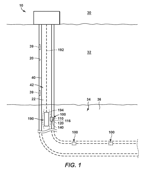
[0023] Fig. 1 is a schematic representation of a hydrocarbon well 10 that
may include
and/or utilize a shockwave generation device 190 according to the present
disclosure.
Hydrocarbon well 10 includes a wellbore 20 that extends from a surface region
30, within a
CA 03007059 2018-05-31
WO 2017/095497 PCT/US2016/051509
subsurface region 32, within a subterranean formation 34 of subsurface region
32, and/or
between the surface region and the subterranean formation. Subterranean
formation 34
includes a reservoir fluid 36, such as a liquid hydrocarbon and/or a gaseous
hydrocarbon, and
hydrocarbon well 10 may be utilized to produce, pump, and/or convey the
reservoir fluid from
5 the subterranean formation and/or to the surface region. Wellbore 20 may
include and/or be a
vertical wellbore, as illustrated in solid lines in Fig. 1. Additionally or
alternatively, and as
illustrated in dashed lines, wellbore 20 also may include and/or be a
horizontal wellbore 20
and/or a deviated wellbore 20.
[0024] Hydrocarbon well 10 further includes wellbore tubular 40, which
extends within
to wellbore 20 and defines a tubular conduit 42. Wellbore tubular 40
includes a plurality of
selective stimulation ports (SSPs) 100. SSPs 100 are illustrated in dashed
lines in Fig. 1 to
indicate that the SSPs may be operatively attached to and/or may form a
portion of any suitable
component of wellbore tubular 40. SSPs 100 may be configured to be operatively
attached to
wellbore tubular 40 prior to the wellbore tubular being located, placed,
and/or installed within
wellbore 20.
[0025] SSPs 100 may be operatively attached to wellbore tubular 40 in any
suitable
manner. As examples, SSPs 100 may be operatively attached to wellbore tubular
40 via one
or more of a threaded connection, a glued connection, a press-fit connection,
a welded
connection, and/or a brazed connection.
[0026] As also illustrated in Fig. 1, hydrocarbon well 10 also includes
and/or has associated
therewith shockwave generation device 190. Shockwave generation device 190 may
be
configured to generate a shockwave 194 within a wellbore fluid 22 that extends
within tubular
conduit 42, as discussed in more detail herein. The shockwave propagates
within the wellbore
fluid and/or propagates from the shockwave generation device to the selective
stimulation port
within and/or via the wellbore fluid.
[0027] In addition, the shockwave is attenuated by the wellbore fluid, and
this attenuation
may include attenuation by at least a threshold attenuation rate. As an
example, the shockwave
may have a peak shockwave intensity proximate the shockwave generation device
and may
decay, or decrease in intensity, with distance from the shockwave generation
device. Under
these conditions, the threshold shockwave intensity may be less than a
threshold fraction of the
peak shockwave intensity. Examples of the threshold attenuation rate include
attenuation rates
of at least 1 megapascal per meter (MPa/m), at least 2 MPa/m, at least 4
MPa/m, at least 6
MPa/m, at least 8 MPa/m, at least 10 MPa/m, at least 12 MPa/m, at least 14
MPa/m, at least 16
MPa/m, at least 18 MPa/m, and/or at least 20 MPa/m.
CA 03007059 2018-05-31
WO 2017/095497 PCT/US2016/051509
6
[0028] SSPs 100 are configured to selectively transition from a closed
state, in which fluid
flow therethrough (i.e., between the tubular conduit and the subterranean
formation) is blocked,
restricted, and/or occluded, to an open state, in which fluid flow
therethrough is permitted,
responsive to receipt of, or responsive to experiencing, a shockwave of
greater than a threshold
shockwave intensity. As an example, and as illustrated in dashed lines in Fig.
1, SSPs 100 may
include an SSP body 110 that defines an SSP conduit 116, which extends between
tubular
conduit 42 and wellbore 20 and/or between tubular conduit 42 and subterranean
formation 34.
SSPs 100 further may include an isolation device 120 and a sealing device seat
140.
[0029] Isolation device 120 may include an isolation disk that extends
across SSP conduit
to 116 when the SSP is in the closed state and that separates from SSP body
110 responsive to
receipt of the shockwave with greater than the threshold shockwave intensity,
such as to permit
fluid flow through SSP conduit 116 when the SSP is in the open state.
Additionally or
alternatively, isolation device 120 may include a frangible disk that extends
across SSP conduit
116 when the SSP is in the closed state and that breaks apart responsive to
receipt of the
shockwave with greater than the threshold shockwave intensity, such as to
pennit fluid flow
through SSP conduit 116 when the SSP is in the open state.
[0030] Sealing device seat 140 may extend within tubular conduit 42 and
may be shaped
to form a fluid seal with a sealing device, such as a ball sealer, that flows
into engagement with
the sealing device seat. Formation of the fluid seal may selectively restrict
fluid flow from
tubular conduit 42 and into wellbore 20 and/or subterranean formation 34 via
SSP conduit 116.
Sealing device seat 140 may be a preformed sealing device seat that has a
predetermined
geometry prior to wellbore tubular 40 being located within wellbore 20.
Additionally or
alternatively, sealing device seat 140 may include and/or be a corrosion-
resistant sealing device
seat and/or an erosion-resistant, or abrasion-resistant, sealing device seat.
[0031] Since shockwave 194 is attenuated by wellbore fluid 22, the
shockwave may have
sufficient energy (i.e., may have greater than the threshold shockwave
intensity) to transition a
first SSP 100, which is less than a threshold distance from the shockwave
generation device
when the shockwave generation device generates the shockwave, from the closed
state to the
open state. However, the shockwave may have insufficient energy to transition
a second SSP
100, which is greater than the threshold distance from the shockwave
generation device when
the shockwave generation device generates the shockwave, from the closed state
to the open
state.
[0032] Stated another way, the plurality of explosive charges may be
sized such that the
shockwave selectively transitions the first SSP from the closed state to the
open state but does
CA 03007059 2018-05-31
WO 2017/095497 PCT/1JS2016/051509
7
not transition the second SSP from the closed state to the open state. The
threshold distance
also may be referred to herein as a maximum effective distance of the
shockwave and/or of the
shockwave generation device 190 from which the shockwave was generated.
Examples of the
threshold distance include threshold distances of less than 1 meter, less than
2 meters, less than
.. 3 meters, less than 4 meters, less than 5 meters, less than 6 meters, less
than 7 meters, less than
8 meters, less than 10 meters, less than 15 meters, less than 20 meters, or
less than 30 meters
along a length of the tubular conduit.
[0033] Shockwave generation device 190 may include and/or be any suitable
structure that
may, or may be utilized to, generate the shockwave within wellbore fluid 22.
As an example,
to shockwave generation device 190 may be an umbilical-attached shockwave
generation device
190 that may be operatively attached to, or may be positioned within tubular
conduit 42 via, an
umbilical 192, such as a wireline, a tether, tubing, jointed tubing, and/or
coiled tubing. As
another example, shockwave generation device 190 may be an autonomous
shockwave
generation device that may be flowed into and/or within tubular conduit 42
without an attached
is umbilical. When shockwave generation device 190 is an autonomous
shockwave generation
device, hydrocarbon well 10 further may include a wireless downhole
communication network
39, which may be configured to wirelessly communicate with shockwave
generation device
190, such as to convey one or more status signals from the shockwave
generation device to the
surface region and/or to convey one or more control signals from the surface
region to the
20 .. shockwave generation device.
[0034] Fig. 2 is a schematic representation of a shockwave generation
device 190 according
to the present disclosure, while Fig. 3 is a more detailed but still schematic
representation of a
portion of the shockwave generation device of Fig. 2. Fig. 4 is a less
schematic side view of a
shockwave generation device 190 according to the present disclosure, while
Fig. 5 is a cross-
25 sectional view of the shockwave generation device of Fig. 4 taken along
line 5-5 of Fig. 4. Fig.
5 illustrates various relative shapes and orientations for flutes, explosive
charges, and
protective barriers that may be utilized in shockwave generation devices. Fig.
6 is a less
schematic side view of another shockwave generation device 190 according to
the present
disclosure, while Fig. 7 is a cross-sectional view of the shockwave generation
device of Fig. 6
30 taken along line 7-7 of Fig. 6. Fig. 8 illustrates various transverse
cross-sectional shapes for
flutes 504 that may be defined by a core 500 of a shockwave generation device
190 according
to the present disclosure.
[0035] Shockwave generation devices 190 of Figs. 2-8 may include and/or
be a more
detailed example of shockwave generation device 190 of Fig. 1, and any of the
structures,
CA 03007059 2018-05-31
WO 2017/095497 PCT/US2016/051509
8
functions, and/or features that are discussed herein with reference to
shockwave generation
devices 190 of Figs. 2-8 may be included in and/or utilized with shockwave
generation device
190 and/or hydrocarbon well 10 of Fig. 1 without departing from the scope of
the present
disclosure. Similarly, any of the structures, functions, and/or features that
are discussed herein
with reference to shockwave generation device 190 and/or hydrocarbon well 10
of Fig. 1 may
be included in and/or utilized with shockwave generation devices 190 of Figs.
2-8 without
departing from the scope of the present disclosure.
[0036] As illustrated in Fig. 1, shockwave generation device 190 is
configured to generate
shockwave 194 within wellb ore fluid 22 that extends within tubular conduit 42
of wellbore
II) tubular 40. As illustrated in Figs. 2-8, shockwave generation devices
190 include a core 500
and a plurality of explosive charges 520. As illustrated in Figs. 2-4 and 6,
shockwave
generation devices 190 further include a plurality of triggering devices 530.
[0037] Explosive charges 520 are arranged on an external surface 502 of
core 500, and
each triggering device 530 is configured to initiate explosion of a selected
one of the plurality
of explosive charges 520. Stated another way, shockwave generation device 190
may be
configured such that a selected triggering device 530 may initiate explosion
of a selected
explosive charge 520 without initiating explosion of other explosive charges
520 that may be
associated with other triggering devices 530. As such, shockwave generation
device 190 also
may be referred to herein as, or may be, a select-fire shockwave generation
device 190, a
selective-fire, downhole shockwave generation device 190, and/or a shockwave
generation
device 190 that is configured to selectively explode a plurality of explosive
charges 520 and/or
to generate a plurality of shockwaves that are spaced-apart in time.
[0038] It is within the scope of the present disclosure that the phrase
"selected one of the
plurality of explosive charges" may refer to a single explosive charge 520.
Alternatively, it is
also within the scope of the present disclosure that the phrase -selected one
of the plurality of
explosive charges" may refer to two or more spaced-apart, separate, and/or
distinct explosive
charges 520 and also may be referred to herein as a selected portion, a
selected fraction, and/or
a selected subset of the plurality of explosive charges. Thus, a given
triggering device 530 may
initiate explosion of a single explosive charge 520 and/or of a subset of the
plurality of
explosive charges 520. Regardless of the exact configuration, each triggering
device 530 may
initiate explosion of one or more selected and/or predetermined explosive
charges 520 but may
not initiate explosion of each, or every, explosive charge that is included
within shockwave
generation device 190.
CA 03007059 2018-05-31
WO 2017/095497 PCT/US2016/051509
9
[0039] Shockwave generation device 190 may be configured such that the
shockwave
emanates symmetrically, at least substantially symmetrically, isotropically,
and/or at least
substantially isotropically, therefrom. Stated another way, the shockwave
generation device
may be configured such that the shockwave is symmetric, at least substantially
symmetric,
isotropic, and/or at least substantially isotropic within a given transverse
cross-section of the
wellbore tubular in which the shockwave in generated. This symmetric and/or
isotropic
behavior of the shockwave may be accomplished in any suitable manner. As an
example, and
as discussed in more detail herein, explosive charges 520 may be wrapped
around, or at least
substantially around, core 500 and/or external surface 502 thereof
to [0040] Core 500 may include any suitable structure and/or material
that may have, form,
and/or define external surface 502, that may support explosive charges 520,
and/or that may
support triggering devices 530. As examples, core 500 may include and/or be an
elongate core,
a rigid core, a metallic core, a solid core, an elongate rigid core, and/or a
metallic rod. It is
within the scope of the present disclosure that core 500 may be solid, at
least substantially solid,
may not be tubular, does not fully enclose the plurality of explosive charges,
and/or may not
define a void space therewithin.
[0041] Additionally or alternatively, it is also within the scope of the
present disclosure
that core 500 may have and/or define one or more pass-through holes 506, as
illustrated in Figs.
2-3, 5, and 7-8. Pass-through holes 506 may extend along a longitudinal length
of core 500,
and a communication linkage 508 may extend therein, as illustrated in Figs. 2-
3.
Communication linkage 508 may permit and/or provide communication between one
or more
components of shockwave generation device 190 and/or between umbilical 192 and
one or
more components of shockwave generation device 190.
[0042] As illustrated in Figs. 2-3, 5, and 7-8, core 500 further may
have, include, and/or
define one or more flutes 504. Flutes 504 also may be referred to herein as
channels 504 and/or
grooves 504 and may be defined by external surface 502. In addition, flutes
504 may be shaped
and/or configured to receive and/or contain one or more explosive charges 520.
As an example,
each flute 504 may receive and/or contain at least a portion, a majority, or
even an entirety, of
a respective one of the plurality of explosive charges 520.
[0043] As illustrated in Figs. 5 and 8, each flute 504 includes a
respective recess 512 and
a respective opening 514. Both the opening and the recess are defined by core
500, and the
opening provides, or is sized to provide, access to the recess by the
respective one of the
plurality of explosive charges 520. Recesses 512 may include and/or be
elongate recesses that
may extend along the longitudinal length of core 500, that may extend about
and/or around
CA 03007059 2018-05-31
WO 2017/095497 PCT/US2016/051509
core 500, that may spiral around core 500, and/or that may extend
circumferentially around a
transverse cross-section of core 500. Similarly, openings 514 may include
and/or be elongate
openings that may extend along the longitudinal length of core 500, that may
extend about
and/or around core 500, that may spiral around core 500, and/or that may
extend
5 circumferentially around a transverse cross-section of core 500.
[0044] As an example, and as illustrated in Figs. 2-3, flutes 504 may
extend longitudinally
along the longitudinal length of core 500. As another example, and as
illustrated in Figs. 4-5,
flutes 504 may include a plurality of spiraling flutes that wraps around
external surface 502
and/or that spirals along a longitudinal axis of core 500. As yet another
example, and as
II) illustrated in Figs. 6-7, flutes 504 may include a plurality of
circumferential flutes that extends
at least partially, or even completely, around the transverse cross-section of
the core and may
include corresponding circumferential explosive charges 520.
[0045] It is within the scope of the present disclosure that flutes 504
may at least partially,
or even completely, house and/or contain respective explosive charges 520. As
an example,
.. and as illustrated in Fig. 5 at 515, a respective explosive charge 520 may
extend within recess
512 and may not extend and/or project through and/or across opening 514.
Stated another way,
a given explosive charge may have and/or define a respective transverse cross-
sectional area,
a given flute, which receives the given explosive charge, may have and/or
define a respective
transverse cross-sectional area, and the respective transverse cross-sectional
area of the given
explosive charge may be less than the respective transverse cross-sectional
area of the given
flute.
[0046] Such a configuration may be utilized to protect the explosive
charge from damage
due to motion of the shockwave generation device within the tubular conduit
and/or due to
flow of an abrasive material past the shockwave generation device while the
shockwave
generation device is present within the tubular conduit. Additionally or
alternatively, such a
configuration may provide a desired level of focusing, a desired intensity,
and/or a desired
directionality of the shockwave that is generated responsive to explosion of
the given explosive
charge.
[0047] A given flute 504 additionally or alternatively may be shaped
and/or otherwise
configured to protect a given explosive charge 520 such that initiation of
explosion of another,
or an adjacent, explosive charge 520 does not initiate explosion of the given
explosive charge
520. As examples, the given flute 504 may direct the shockwave that is
generated by given
explosive charge 520 away from core 500, may direct the shockwave away from
the other
flutes 504, and/or may direct the shockwave away from other explosive charges
520 that are
CA 03007059 2018-05-31
WO 2017/095497 PCT/US2016/051509
11
associated with the other flutes 504. As additional examples, the given flute
504 and/or the
adjacent flute(s) may be configured to sufficiently shield and/or isolate the
adjacent explosive
charges from the shockwave produced by the given explosive charge 520 to
prevent the
shockwave from the given explosive charge initiating explosion of the adjacent
explosive
charges. Such configurations may permit and/or facilitate each triggering
device 520 to initiate
explosion of one or more selected explosive charges 520 without initiating
explosion of each,
or every, explosive charge that is included within shockwave generation device
190, as
discussed in more detail herein.
[0048] As another example, and as illustrated in Fig. 5 at 516, a
respective explosive charge
io 520 may extend within recess 512 and also may extend and/or project
through and/or across
opening 514. Stated another way, the respective transverse cross-sectional
area of the given
charge may be less than the respective transverse cross-sectional area of the
given flute. Such
a configuration may provide a desired level of focusing, a desired intensity,
and/or a desired
directionality of the shockwave that is generated responsive to explosion of
the given explosive
charge.
[0049] As discussed, core 500 and/or external surface 502 thereof may
define one or more
flutes 504. It is within the scope of the present disclosure that flutes 504
may have and/or
define any suitable cross-sectional, or transverse cross-sectional, shape. As
an example, and
as illustrated in Fig. 5 and in Fig. 8 at 590, flutes 504 may have and/or
define a circular, or at
least partially circular, transverse cross-sectional shape. As another
example, and as illustrated
in Fig. 8 at 592, flutes 504 may have and/or define an arcuate, or at least
partially arcuate,
transverse cross-sectional shape. As yet another example, and as illustrated
in Fig. 8 at 594,
flutes 504 may have and/or define a triangular, at least partially triangular,
V-shaped, or at least
partially V-shaped, transverse cross-sectional shape. As another example, and
as illustrated in
Fig. 8 at 596, flutes 504 may have and/or define a square, at least partially
square, rectangular,
or at least partially rectangular, transverse cross-sectional shape. Flutes
with other regular
and/or irregular geometric transverse cross-sectional shapes also may be
utilized. Additionally
or alternatively, and as discussed herein and illustrated in Fig. 8 at 598,
one or more explosive
charges 520 may extend across a portion of external surface 502 that does not
include a flute.
[0050] Core 500 may be a single-piece and/or monolithic structure.
Alternatively, and as
illustrated in dashed lines in Fig. 6, core 500 may be a multi-piece core that
includes a plurality
of core segments 510. Under these conditions, each core segment 510 may be
operatively
attached to one or more adjacent core segments to form and/or define core 500.
When
shockwave generation device 190 includes core segments 510, it is within the
scope of the
CA 03007059 2018-05-31
WO 2017/095497 PCT/US2016/051509
12
present disclosure that each core segment 510 may have any suitable number of
explosive
charges 520 and/or corresponding triggering devices 530 associated therewith
and/or attached
thereto. As examples, each core segment may have 1, 2, 3, 4, 5, 6, 7, 8, or
more than 8 explosive
charges and/or corresponding triggering devices associated therewith and/or
attached thereto.
[0051] Explosive charges 520 may include and/or be any suitable structure
that may be
adapted, configured, formulated, synthesized, and/or constructed to
selectively explode and/or
to selectively generate the shockwave within the wellbore fluid. An example of
explosive
charges 520 includes a primer cord 522. As an example, shockwave generation
device 190
may include a plurality of lengths of primer cord 522, with each explosive
charge 520 including
io at least one length of primer cord. Primer cord 522 also may be referred
to herein as a
detonation cord 522 and/or as a detonating cord 522 and may be configured to
explode and/or
detonate.
[0052] When shockwave generation device 190 and/or explosive charges 520
thereof
include primer cord 522, the primer cord may have and/or define any suitable
length. As
examples, the length of the primer cord may be at least 0.1 meter (m), at
least 0.2 m, at least
0.3 m, at least 0.4 m, at least 0.5 m, at least 0.6 m, at least 0.7 m, at
least 0.8 m, at least 0.9 m,
at least 1 m, at least 1.25 m, at least 1.5 m, at least 1.75 m, or at least 2
m. Additionally or
alternatively, the length of the primer cord may be less than 5 m, less than
4.5 m, less than 4
in, less than 3.5 in, less than 3 m, less than 2.5 in, less than 2 in, less
than 1.5 m, or less than 1
111.
[0053] Primer cord 522 also may include any suitable amount of an
explosive, such as
gunpowder. As examples, the primer cord may include at least 25 grains of
gunpowder per
meter of length (grains/m), at least 50 grains/m, at least 100 grains/m, at
least 150 grains/m, at
least 200 grains/m, at least 300 grains/m, at least 400 grains/m, at least 500
grains/m, or at least
600 grains/m. Additionally or alternatively, the primer cord may include fewer
than 1000
grains/m, fewer than 900 grains/m, fewer than 800 grains/m, fewer than 700
grains/m, fewer
than 600 grains/m, fewer than 500 grains/m, fewer than 400 grains/m, fewer
than 300 grains/m,
or fewer than 200 grains/m. The amount of explosive, or gunpowder, also may be
expressed
in grams per meter of length (g/m). As examples, the primer cord may include
at least 1.6 g/m,
at least 3.3 g/m, at least 6.5 g/m, at least 9.8 g/m, at least 13 g/m, at
least 19.5 g/m, at least 26
g/m, at least 32.5 g/m, or at least 39 g/m. Additionally or alternatively, the
primer cord may
include fewer than 65 g/m, fewer than 58.5 g/m, fewer than 52 g/m, fewer than
45.5 g/m, fewer
than 39 g/m, fewer than 32.5 On, fewer than 26 g/m, fewer than 19.5 Oil, or
fewer than 13
g/m.
CA 03007059 2018-05-31
WO 2017/095497 PCT/US2016/051509
13
[0054] In general, the length of the primer cord and/or the amount of
explosive per unit
length of the primer cord may be selected to provide a desired intensity, or a
desired maximum
intensity, for the shockwave when the primer cord explodes within the wellbore
fluid. As an
example, the length of the primer cord and/or the amount of explosive per unit
length of the
primer cord may be selected such that the maximum intensity of the shockwave
is greater than
the threshold shockwave intensity necessary to transition selective
stimulation port 100 of Fig.
1 from the closed state to the open state. As another example, the length of
the primer cord
and/or the amount of explosive charge per unit length of the primer cord may
be selected such
that maximum intensity of the shockwave is less than an intensity that would
damage, or
to rupture, a wellbore tubular that defines a tubular conduit within which
the shockwave is
generated and/or such that the shockwave has insufficient energy, or
intensity, to rupture or
damage the wellbore tubular.
[0055] Stated another way, each explosive charge 520 may be sized such
that the
shockwave has a maximum pressure of at least 100 megapascals (MPa), at least
110 MPa, at
is least 120 MPa, at least 130 MPa, at least 140 MPa, at least 150 MPa, at
least 160 MPa, at
least 170 MPa, at least 180 MPa, at least 190 MPa, at least 200 MPa, at least
250 MPa, at
least 300 MPa, at least 400 MPa, or at least 500 MPa. Additionally or
alternatively, each
explosive charge 520 may be sized such that the shockwave has a maximum
duration of less
than 1 second, less than 0.9 seconds, less than 0.8 seconds, less than 0.7
seconds, less than 0.6
20 seconds, less than 0.5 seconds, less than 0.4 seconds, less than 0.3
seconds, less than 0.2
seconds, less than 0.1 seconds, less than 0.05 seconds, or less than 0.01
seconds. The maximum
duration may be a maximum period of time during which the shockwave has
greater than the
threshold shockwave intensity within the wellbore tubular. Additionally or
alternatively, the
maximum duration may be a maximum period of time during which the shockwave
has a
25 shockwave intensity of greater than 68.9 MPa (10,000 pounds per square
inch) within any
portion of the wellbore tubular.
[0056] Each explosive charge 520 additionally or alternatively may be
sized such that the
shockwave exhibits greater than the threshold shockwave intensity within the
tubular conduit
over a maximum effective distance, or length, of and/or along the tubular
conduit. Examples
30 of the maximum effective distance are disclosed herein.
[0057] As discussed, explosive charges 520 may be arranged on external
surface 502 of
core 500, may be wrapped around external surface 502 of core 500, and/or may
extend at least
partially within one or more flutes 504 that may be defined by external
surface 502 of core 500.
This may include explosive charges that extend longitudinally along the length
of core 500, as
CA 03007059 2018-05-31
WO 2017/095497 PCT/US2016/051509
14
illustrated in Figs. 2-3, explosive charges that wrap and/or spiral along the
length of the core,
as illustrated in Figs. 4-5, and/or explosive charges that encircle a
transverse cross-section of
the core, as illustrated in Figs. 6-7.
[0058] Explosive charges 520 and core 500 may be oriented relative to one
another such
that, when shockwave generation device 190 is immersed within wellbore fluid
22, as
illustrated in Fig. 1, the explosive charges extend at least partially between
at least a portion of
the core and the wellbore fluid. Stated yet another way, explosive charges 520
and core 500
may be oriented relative to one another such that, when shockwave generation
device 190 is
present within tubular conduit 42, as illustrated in Fig. 1, the explosive
charges extend at least
io partially between external surface 502 and wellbore tubular 40.
[0059] Stated yet another way, and when the shockwave generation device is
immersed
within the wellbore fluid, at least a portion, or even a majority, of the
explosive charges is
exposed to the wellbore fluid, is in contact with the wellbore fluid, is in
fluid contact with the
wellbore fluid, and/or is not isolated from the wellbore fluid by the core. As
examples, at least
50%, at least 60%, at least 70%, at least 80%, at least 90%, or at least 95%
of a length of each
of explosive charges 520 may be exposed to, in contact with, and/or in fluid
contact with the
wellbore fluid.
[0060] Shockwave generation device 190 may include any suitable number of
explosive
charges 520. As examples, the shockwave generation device may include at least
2, at least 3,
at least 4, at least 5, at least 6, at least 7, or at least 8 explosive
charges. Additionally or
alternatively, the shockwave generation device may include 20 or fewer, 18 or
fewer, 16 or
fewer, 14 or fewer, 12 or fewer, 10 or fewer, 8 or fewer, 6 or fewer, or 4 or
fewer explosive
charges.
[0061] Triggering devices 530 may include and/or be any suitable structure
that may be
configured to selectively initiate explosion of selected ones of the plurality
of explosive
charges. As an example, triggering devices 530 may include and/or be
electrically actuated
triggering devices, separately addressable switches, and/or blast caps 532. As
a more specific
example, each triggering device 530 may include a uniquely addressable switch
that may be
configured to initiate explosion of a selected one of the plurality of
explosive charges
responsive to receipt of a unique code. The unique code of each triggering
device may be
different from the unique code of each of the other triggering devices,
thereby permitting
selective actuation of a given triggering device.
[0062] Each triggering device 530 may be configured to initiate explosion
of a selected one
of the plurality of explosive charges independent from a remainder of the
explosive charges.
CA 03007059 2018-05-31
WO 2017/095497 PCT/US2016/051509
Stated another way, each triggering device is configured to be actuated
independently from a
remainder of the triggering devices. Thus, shockwave generation device 190 may
be
configured such that actuation of a given triggering device initiates
explosion of a
corresponding explosive charge but does not, necessarily, result in actuation
of another
5 triggering device and/or initiate explosion of another explosive charge
that is associated with
the other triggering device.
[0063] As illustrated in Figs. 2-4 and 6, triggering devices 530 may form
a portion of a
triggering assembly 528. Triggering assembly 528 may be operatively attached
to core 500
and/or may form a portion of core 500. In addition, and when shockwave
generation device
10 190 is submerged within the wellbore fluid, triggering assembly 528 may
at least partially, or
even completely, isolate at least a portion, or even all, of each triggering
device 530 from the
wellbore fluid. As an example, and as illustrated in Figs. 2-3, triggering
assembly 528 may
include and/or defme an enclosed volume 529 that is fluidly isolated from the
wellbore fluid
and/or that contains and/or houses the triggering devices.
15 [0064] As illustrated in dashed lines in Figs. 2-3, 5, and 7,
shockwave generation device
190 and/or explosive charge 520 thereof further may include a protective
barrier 524.
Protective barrier 524 may be configured to at least partially, or even
completely, isolate, or
fluidly isolate, explosive charges 520 from the wellbore fluid when the
shockwave generation
device is submerged within the wellbore fluid. Such isolation may prevent
contamination of
the explosive charge by the wellbore fluid, may prevent degradation of the
explosive charge
by the wellbore fluid, may resist permeation of the wellbore fluid into the
explosive charge,
and/or may resist abrasion of the explosive charge by an abrasive material,
such as a proppant,
that may be present within the wellbore fluid and/or by wellbore tubular 40
when the
shockwave generation device is present within tubular conduit 42, as
illustrated in Fig. 1.
[0065] As illustrated in Fig. 2, protective barrier 524 may extend along a
length, or even
an entire length, of explosive charge 520. As illustrated in Fig. 5 at 525,
protective barrier 524
may extend at least partially, or even completely, around a transverse cross-
section of a given
explosive charge 520. Additionally or alternatively, and as illustrated in
Fig. 5 at 526,
protective barrier 524 may extend at least partially, or even completely,
around a transverse
cross-section of core 500 and/or of external surface 502 thereof
[0066] It is within the scope of the present disclosure that shockwave
generation device
190 may include a plurality of protective barriers 524 and that each
protective barrier 524 may
extend around a corresponding explosive charge 520, may extend along a length
of the
corresponding explosive charge, may extend along an entirety of the length of
the
CA 03007059 2018-05-31
WO 2017/095497 PCT/US2016/051509
16
corresponding explosive charge, and/or may extend across a respective portion
of external
surface 502 of core 500. Additionally or alternatively, it is also within the
scope of the present
disclosure that a single protective barrier 524 may extend at least partially
around two or more
of the explosive charges and/or may extend across a majority, or even all, of
external surface
502 of core 500.
[0067] Protective barrier 524 may include and/or be formed from any
suitable material. As
examples, the protective barrier may include and/or be anon-metallic
protective barrier and/or
may be formed from a polymeric material, an elastomeric material, and/or a
resilient material.
As a more specific example, protective barrier 524 may include, or be, a
resilient sleeve and/or
to cylinder that extends around at least one explosive charge 520 and/or
that extends around
external surface 502. As another more specific example, protective barrier 524
may include,
or be, an adhesive tape that is taped to at least one explosive charge 520
and/or to external
surface 502. As additional specific examples, protective barrier 524 may
include, or be, a
ceramic tube, or sleeve, that houses and/or contains one or more explosive
charges 520 and/or
at least a portion of core 500. As further examples, protective barrier 524
may include, or be,
a hollow steel (or other metallic) carrier, or sleeve, that includes a
plurality of ports, with the
ports being present prior to explosion of the explosive charges and permitting
the shockwave
to exit the hollow steel carrier upon explosion of a given explosive charge
520.
[0068] As illustrated in solid lines in Figs. 2-3, shockwave generation
device 190 may
include a first plurality of explosive charges 520 and a corresponding first
plurality of triggering
devices 530. In addition, and as illustrated in dashed lines in Figs. 2-3,
shockwave generation
device 190 also may include a second plurality of explosive charges 520 and a
corresponding
second plurality of triggering devices 530. The first plurality of explosive
charges and the first
plurality of triggering devices together may define a first shockwave
generation unit 198 (as
indicated in solid lines), and the second plurality of explosive charges and
the second plurality
of triggering devices together may define a second shockwave generation unit
198 (as indicated
in dashed lines).
[0069] The first shockwave generation unit and the second shockwave
generation unit may
be operatively attached to one another, in an end-to-end fashion, to form
and/or define
shockwave generation device 190. As an example, an end region of the first
shockwave
generation unit may be operatively attached to an end region of the second
shockwave
generation unit, such as via a coupling structure 562 and/or such that a
longitudinal axis of the
first shockwave generation unit is aligned, or at least substantially aligned,
with a longitudinal
axis of the second shockwave generation unit. Under these conditions, an
overall, or collective,
CA 03007059 2018-05-31
WO 2017/095497 PCT/US2016/051509
17
length of the first shockwave generation device in combination with the second
shockwave
generation device may be less than 10 meters, less than 8 meters, less than 6
meters, less than
meters, less than 4 meters, or less than 3 meters.
[0070] It is within the scope of the present disclosure that shockwave
generation device
5 190 may include any suitable number of shockwave generation units 198 and
that each
shockwave generation unit 198 may include any suitable number of explosive
charges 520 and
corresponding triggering devices 530. As examples, shockwave generation device
190 may
include at least 2, at least 3, at least 4, at least 5, at least 6, at least
8, or at least 10 shockwave
generation units.
II) [0071] Shockwave generation device 190 may have any suitable length,
or overall length.
As examples, the overall length of the shockwave generation device may be less
than 40 meters,
less than 35 meters, less than 30 meters, less than 25 meters, or less than 20
meters. The
shockwave generation device also may have any suitable maximum transverse
cross-sectional
extent, or area. As examples, the maximum transverse cross-sectional extent
may be less than
0.2 meters (m), less than 0.15 m, less than 0.1 m, less than 0.8 in, less than
0.067 in, less than
0.06 m, or less than 0.05 m.
[0072] In order to provide clearance for motion of the shockwave
generation device within
the tubular conduit and/or to provide clearance for flow of ball sealers
therepast, the maximum
transverse cross-sectional extent of the shockwave generation device may be
less than a cross-
sectional diameter of the tubular conduit. As examples, the maximum transverse
cross-
sectional extent of the shockwave generation device may be at least 0.1 meter
(m), at least 0.08
m, at least 0.06 m, at least 0.04 m, at least 0.031 m, at least 0.03 m, or at
least 0.025 m less than
the cross-sectional diameter of the tubular conduit.
[0073] As discussed, and illustrated in Figs. 1-2, shockwave generation
device 190 may
include and/or be an umbilical-attached shockwave generation device 190 that
is operatively
attached to an umbilical 192. Such an umbilical may permit and/or facilitate
positioning of the
shockwave generation device within the tubular conduit and/or may permit
and/or facilitate
communication with the shockwave generation device, such as from surface
region 30 of Fig.
1. As an example, umbilical 192 may convey one or more status signals from the
shockwave
.. generation device to the surface region and/or may convey one or more
control signals from
the surface region to the shockwave generation device. Such an umbilical-
attached shockwave
generation device may include an anchor 193 that may be configured to receive
and/or to be
operatively attached to the umbilical, as illustrated in Fig. 2.
CA 03007059 2018-05-31
WO 2017/095497 PCT/US2016/051509
18
[0074] As illustrated in Figs. 2-4 and 6, shockwave generation device 190
further may
include a detector 540. Detector 540 may be configured to detect any suitable
property and/or
parameter of shockwave generation device 190, of wellbore fluid 22, of
wellbore tubular 40,
and/or of tubular conduit 42 (as illustrated in Fig. 1). As an example,
detector 540 may be
configured to detect a location of the shockwave generation device within the
wellbore tubular.
[0075] An example of detector 540 includes a casing collar locator that is
configured to
detect, or count, a casing collar of the wellbore tubular. Another example of
detector 540
includes a magnetic field detector that is configured to detect a magnetic
field that emanates
from a magnetic material that defines a portion of the wellbore tubular and/or
a selective
stimulation port 100 of the wellbore tubular. Yet another example of detector
540 includes a
radioactivity detector that is configured to detect a radioactive material
that forms and/or
defines a portion of the wellbore tubular and/or a selective stimulation port
100 of the wellbore
tubular. Another example of detector 540 includes a depth detector that is
configured to detect
a depth of the shockwave generation device within the tubular conduit. Yet
another example
of detector 540 includes a speed detector that is configured to detect a speed
of the shockwave
generation device within the tubular conduit. Another example of detector 540
includes a timer
that is configured to measure a time associated with motion of the shockwave
generation device
within the tubular conduit. Yet another example of detector 540 includes a
downhole pressure
sensor that is configured to detect a pressure within the wellbore fluid that
is proximal thereto.
Another example of detector 540 includes a dow-nhole temperature sensor that
is configured to
detect a temperature within the wellbore fluid.
[0076] As illustrated in dashed lines in Figs. 2-4, and 6, shockwave
generation device 190
further may include a controller 550. Controller 550 may be adapted,
configured, designed,
constructed, and/or programmed to control the operation of at least a portion
of the shockwave
generation device. This control may be based, at least in part, on the
property and/or parameter
that is detected by detector 540. As an example, and as illustrated in Fig. 3,
shockwave
generation device 190 may include a communication linkage 552 between
controller 550 and
detector 540.
[0077] As an example, detector 540 may be configured to generate a
location signal that is
indicative of the location of the shockwave generation device within the
wellbore tubular and
to convey the location signal to the controller via the communication linkage.
In addition, the
controller may be programmed to control the operation of the shockwave
generation device
based, at least in part, on the location signal. As a more specific example,
controller 550 may
be programmed to actuate a selected one of the plurality of triggering devices
530 based, at
CA 03007059 2018-05-31
WO 2017/095497 PCT/US2016/051509
19
least in part, on the location signal and/or responsive to receipt of the
location signal. The
triggering device then may initiate explosion of a corresponding one of the
plurality of
explosive charges 520.
[0078] As another example, detector 540 may be configured to detect a
pressure pulse
within the wellbore fluid, such as may be deliberately and/or purposefully
generated within the
wellbore fluid by an operator of the hydrocarbon well. Under these conditions,
detector 540
may generate a pressure pulse signal responsive to receipt of the pressure
pulse and may
provide the pressure pulse signal, via the communication linkage, to
controller 550. Controller
550 then may be programmed to actuate the selected one of the plurality of
triggering devices
io .. 530 based, at least in part, on the pressure pulse signal and/or
responsive to receipt of the
pressure pulse signal.
[0079] Additionally or alternatively, controller 550 may be configured to
actuate the
selected one of the plurality of triggering devices responsive to receipt of a
triggering signal.
The triggering signal may be provided to the controller in any suitable
manner. As an example,
and as illustrated in Fig. 1, wellbore 20 may include a downhole wireless
communication
network 39, and controller 550 may be adapted, configured, designed,
constructed, and/or
programmed to receive the triggering signal from the downhole wireless
communication
network. As another example, and as also illustrated in Fig. 1, shockwave
generation device
190 may be an umbilical-attached shockwave generation device that is attached
to an umbilical
192. Under these conditions, controller 550 may be adapted, configured,
designed,
constructed, and/or programmed to receive the triggering signal from the
umbilical, and it is
within the scope of the present disclosure that the umbilical may be
configured to provide serial
communication between the controller and surface region 30.
[0080] Controller 550 may include any suitable structure. As examples,
controller 550
may include and/or be a special-purpose controller, an analog controller, a
digital controller,
and/or a logic device.
[0081] As illustrated in dashed lines in Fig. 2, and in solid lines in
Figs. 4 and 6, shockwave
generation device 190 further may include a guide structure 560. Guide
structure 560 may be
adapted, configured, sized, and/or shaped to passively guide and/or direct the
shockwave
generation device when the shockwave generation device moves and/or translates
within the
tubular conduit.
[0082] As also illustrated in dashed lines in Fig. 2, shockwave generation
device 190 may
include a bridge plug setting structure 566. Bridge plug setting structure 566
may be configured
to set, or to selectively set, a bridge plug within the tubular conduit.
CA 03007059 2018-05-31
WO 2017/095497 PCT/US2016/051509
[0083] As also illustrated in dashed lines in Fig. 2, shockwave generation
device 190 may
include a ball sealer holder 580. Ball sealer holder 580 may contain and/or
house one or more
ball sealers 582 and may be configured to selectively release the one or more
ball sealers. As
an example, ball sealer holder 580 may be configured to selectively release at
least one ball
5 sealer for each explosive charge 520 that is associated with shockwave
generation device 190
and/or for each selective stimulation port that is opened by each explosive
charge. This may
include releasing the at least one ball sealer responsive to explosion of a
corresponding
explosive charge 520, prior to explosion of the corresponding explosive
charge, and/or
subsequent to explosion of the corresponding explosive charge.
to [0084] As illustrated in dashed lines in Fig. 2, shockwave
generation device 190 further
may include and/or have operatively attached thereto one or more weights 564.
Weights 564
may be configured to increase an average density of the shockwave generation
device, to
increase a weight of the shockwave generation device, and/or to regulate an
orientation of the
shockwave generation device when the shockwave generation device is present
within the
15 wellbore conduit. As an example, and as illustrated in Fig. 2, weights
564 may be oriented off-
center with respect to a transverse cross-section of shockwave generation
device 190 and
thereby may cause the shockwave generation device to orient within the
wellbore conduit in a
predetermined, or desired, manner.
[0085] It is within the scope of the present disclosure that, subsequent
to actuation of
20 explosive charges 520, shockwave generation device 190 may be adapted,
configured,
designed, and/or constructed to break apart and/or to dissolve within the
tubular conduit. As
an example, shockwave generation device 190 may be formed from a frangible
material that
breaks apart responsive to explosion of a last, or final, explosive charge
520.
[0086] As another example, shockwave generation device 190 may be formed
from a
corrodible material that corrodes within the wellbore fluid. This may include
corroding within
a timeframe that is shorter than a timeframe for other components of the
hydrocarbon well,
such as wellbore tubular 40. As an example, the shockwave generation device
may be
configured to remain intact during generation of the shockwaves and to
corrode, completely
corrode, and/or break apart between completion of stimulation operations that
utilize the
shockwave generation device and initiation of production of the reservoir
fluid from the
hydrocarbon well.
[0087] As yet another example, shockwave generation device 190 may be
formed from a
soluble material that is soluble within the wellbore fluid. This soluble
material may be selected
to dissolve within a timeframe that is shorter than the timeframe for other
components of the
CA 03007059 2018-05-31
WO 2017/095497 PCT/US2016/051509
21
hydrocarbon well, such as wellbore tubular 40, to corrode and/or break apart.
As an example,
the shockwave generation device may be configured to remain intact during
generation of the
shockwaves and to dissolve, completely dissolve, and/or break apart between
completion of
stimulation operations that utilize the shockwave generation device and
initiation of production
of the reservoir fluid from the hydrocarbon well.
[0088] As discussed in more detail herein, shockwave generation device 190
may be
configured to generate the shockwave to transition a selective stimulation
port, such as SSP
100 of Fig. 1, from a closed state to an open state, to permit stimulation of
a subterranean
formation, such as subterranean formation 34 of Fig. 1, and/or to permit an
inrush of fluid into
II) the wellbore tubular from the subterranean formation. Under these
conditions, shockwave
generation device 190 may be adapted, configured, designed, constructed,
and/or sized to
remain in the tubular conduit during stimulation of the subterranean
formation, during flow of
a stimulant fluid through and/or within the tubular conduit and past the
shockwave generation
device, and/or during the inrush of fluid into the wellbore tubular.
[0089] Fig. 9 is a flowchart depicting methods 800, according to the
present disclosure, of
generating a plurality of shockwaves within a wellbore fluid that extends
within a tubular
conduit, while Figs. 10-14 are schematic cross-sectional views of a portion of
a process flow
340 for generating a plurality of shockwaves 194 within a subterranean
formation 34. As
illustrated in process flow 340 of Figs. 10-14, a shockwave generation device
190 may be
.. positioned within a wellbore tubular 40 that defines a tubular conduit 42
and extends within
subterranean formation 34. The wellbore tubular may include a plurality of
selective
stimulation ports (SSPs) 100 that initially may be in a closed state 121. The
plurality of SSPs
100 may be spaced apart along the wellbore tubular, such as along the
longitudinal length of
the wellbore tubular and/or radially around the circumference of the wellbore
tubular.
[0090] Methods 800 may include pressurizing the tubular conduit at 805 and
include
positioning the shockwave generation device at 810. Methods 800 further may
include
detecting that the shockwave generation device is within a first region of the
tubular conduit at
815 and include actuating a first triggering device at 820. Methods 800
further may include
transitioning a first selective stimulation port at 825, stimulating a first
region of the
subterranean formation at 830, and/or flowing a first ball sealer at 835.
Methods 800 include
moving the shockwave generation device at 840 and may include repressurizing
the tubular
conduit at 845 and/or detecting that the shockwave generation device is in a
second region of
the tubular conduit at 850. Methods 800 further include actuating a second
triggering device
CA 03007059 2018-05-31
WO 2017/095497 PCT/US2016/051509
22
at 855 and may include transitioning a second selective stimulation port at
860, stimulating a
second region of the subterranean formation at 865, and/or flowing a second
ball sealer at 870.
[0091] Pressurizing the tubular conduit at 805 may include pressurizing
the tubular conduit
in any suitable manner. As an example, the pressurizing at 805 may include
pressurizing with
a stimulant fluid, such as by flowing the stimulant fluid into the tubular
conduit and/or
providing the stimulant fluid to the tubular conduit. The pressurizing at 805
may be prior to
the positioning at 810, concurrently with the positioning at 810, subsequent
to the positioning
at 810, prior to the detecting at 815, concurrently with the detecting at 815,
subsequent to the
detecting at 815, and/or prior to the actuating at 820. The pressurizing at
805 is illustrated in
II) Fig. 10, wherein a stimulant fluid 70 is provided to tubular conduit 42
of wellbore tubular 40.
As also illustrated in Fig. 10, and during the pressurizing at 805, SSPs 100
associated with
wellbore tubular 40 may be in closed state 121, thereby permitting
pressurization of the tubular
conduit.
[0092] Positioning the shockwave generation device at 810 may include
positioning any
suitable shockwave generation device, including shockwave generation device
190 of Figs. 2-
8 and 10-14, within the first region of the tubular conduit. This is
illustrated in Fig. 10, with
shockwave generation device 190 being positioned within first region 105 of
tubular conduit
42.
[0093] The positioning at 810 may be accomplished in any suitable manner.
As an
example, the positioning at 810 may include flowing and/or conveying the
shockwave
generation device in a downhole direction, such as downhole direction 29 of
Fig. 10, within a
flow of the stimulant fluid. As another example, the positioning at 810 may
include positioning
with an umbilical, such as a wireline, as illustrated in Fig. 10 at 192. As
yet another example,
the positioning at 810 may include autonomously positioning the shockwave
generation device.
As another example, the positioning at 810 may include landing, resting,
stopping, and/or
receiving the shockwave generation device on and/or with any suitable latch,
catch, receiver,
and/or platform that may form a portion of the wellbore tubular and/or of the
SSP, and/or that
may extend within the tubular conduit.
[0094] Detecting that the shockwave generation device is within the first
region of the
tubular conduit at 815 may include detecting in any suitable manner. As an
example, the
detecting at 815 may include detecting via and/or utilizing detector 540 of
Figs. 2-3.
Additionally or alternatively, the detecting at 815 may include one or more of
detecting a casing
collar of the wellbore tubular, detecting a velocity of the shockwave
generation device within
the wellbore tubular, detecting a residence time of the shockwave generation
device within the
CA 03007059 2018-05-31
WO 2017/095497 PCT/US2016/051509
23
wellbore tubular, detecting a distance of flow of the shockwave generation
device along the
length of the wellbore tubular, detecting a depth of the shockwave generation
device within the
wellbore tubular, detecting a magnetic material that forms a portion of the
wellbore tubular
and/or SSP, and/or detecting a radioactive material that forms a portion of
the wellbore tubular
and/or SSP.
[0095] Actuating the first triggering device at 820 may include actuating
the first triggering
device to initiate explosion of a first explosive charge of a plurality of
explosive charges of the
shockwave generation device. Additionally or alternatively, the actuating at
820 may include
actuating to generate a first shockwave within the first region of the tubular
conduit. This is
to illustrated in Fig. 11, where a shockwave 194 is illustrated within
first region 105 of tubular
conduit 42.
[0096] It is within the scope of the present disclosure that the actuating
at 820 may include
actuating responsive to any suitable criteria. As an example, the actuating at
820 may be
initiated responsive to the detecting at 815 (i.e., responsive to detecting
that the shockwave
generation device is within the first region of the tubular conduit). As
another example, the
actuating at 820 may include actuating subsequent to the positioning at 810
and/or responsive
to completion of the positioning at 810.
[0097] It is also within the scope of the present disclosure that the
actuating at 820 may
include actuating in any suitable manner. As examples, the actuating at 820
may include
electrically actuating, mechanically actuating, chemically actuating,
wirelessly actuating,
and/or actuating responsive to receipt of a pressure pulse.
[0098] Transitioning the first selective stimulation port at 825 may
include transitioning
one or more first selective stimulation ports (SSP) from respective closed
states to respective
open states responsive to receipt of the first shockwave with greater than the
threshold
shockwave intensity by the one or more first SSPs. When in the closed state,
the SSPs resist
fluid flow therethrough, while, when in the open state, the SSPs permit fluid
flow therethrough.
[0099] This is illustrated in Fig. 11, with first SSPs 100 that are
present within first region
105 of tubular conduit 42 being transitioned to open state 122 responsive to
receipt of
shockwave 194. As also illustrated in Fig. 11, the transitioning at 825
further may include
transitioning the first SSP 100 to open state 122 while maintaining one or
more second SSPs
100 that are uphole from the first SSP in respective closed states 121. The
first SSPs and the
second SSPs also may be referred to herein as being spaced-apart, or
longitudinally spaced-
apart, along a length of the wellbore tubular, and this selective
transitioning of the first SSP
and not the other SSPs may be due to the limited, or maximum, effective
distance, or
CA 03007059 2018-05-31
WO 2017/095497 PCT/US2016/051509
24
propagation distance, of the shockwave within a wellbore fluid 22 that extends
within tubular
conduit 42, as is discussed herein. Examples of the maximum effective distance
of the
shockwave are disclosed herein, and the one or more first SSPs and the one or
more second
SSPs may be spaced-apart by greater than the maximum effective distance of the
shockwave.
1001001 Stimulating the first region of the subterranean formation at 830 may
include
stimulating any suitable first region of the subterranean formation that may
be proximal to
and/or associated with the first region of the tubular conduit. The
stimulating at 830 may
include stimulating responsive to. or directly responsive to, the actuating at
820 and/or the
transitioning at 825. As an example, and as illustrated in Fig. 11,
transitioning the one or more
to first SSPs 100 to open state 122 may permit stimulant fluid 70 to flow
from tubular conduit 42
and into subterranean formation 34, thereby permitting stimulation of the
subterranean
formation.
1001011 Flowing the first ball sealer at 835 may include providing one or more
first ball
sealers from the surface region and flowing the one or more first ball
sealers, via the tubular
conduit, to, into contact with, or into engagement with, the one or more first
SSPs and/or with
one or more sealing device seats 140 thereof Additionally or alternatively,
the flowing at 835
may include releasing the one or more first ball sealers from the shockwave
generation device
and flowing the one or more first ball sealers, via the tubular conduit, to
and/or into engagement
with the one or more first SSPs. Engagement between the one or more first ball
sealers and the
one or more first SSPs may restrict fluid flow from the tubular conduit via
the one or more first
SSPs.
[00102] This is illustrated in Figs. 12-13. In Fig. 12, sealing devices 142
in the form of ball
sealers are depicted as flowing within a flow of stimulant fluid 70 in
downhole direction 29
within tubular conduit 42. In Fig. 13, the ball sealers have engaged with the
one or more first
SSPs that are present within first region 105 of the tubular conduit and
restrict fluid flow
therethrough.
[00103] The flowing at 835 may be performed with any suitable timing and/or
sequence
within methods 800. As an example, the flowing at 835 may be performed
subsequent to the
pressurizing at 805, subsequent to the positioning at 810, subsequent to the
detecting at 815,
subsequent to the actuating at 820, subsequent to the transitioning at 825,
and/or subsequent to
the stimulating at 830. Additionally or alternatively, and when the
pressurizing at 805 includes
providing the stimulant fluid to the tubular conduit, the flowing at 835 may
be performed at
least partially concurrently with the providing.
CA 03007059 2018-05-31
WO 2017/095497 PCT/US2016/051509
[00104] Moving the shockwave generation device at 840 may include moving the
shockwave generation device to a second region of the tubular conduit that is
spaced-apart from
the first region of the tubular conduit. It is within the scope of the present
disclosure that the
moving at 840 may be accomplished in any suitable manner. As an example, the
moving at
5 840 may include moving with, via, and/or utilizing an umbilical, such as
a wireline. As a more
specific example, and as illustrated in the transition from Fig. 12 to Fig.
13, the moving at 840
may include moving shockwave generation device 190 in an uphole direction 28
such that the
shockwave generation device is within a second region 107 of tubular conduit
42.
[00105] Repressurizing the tubular conduit at 845 may include repressurizing
with the
to stimulant fluid. The repress urizing at 845 may be performed at least
substantially similar to
the pressurizing at 805. It is within the scope of the present disclosure
that, when the
pressurizing at 805 includes flowing and/or providing the stimulant fluid to
the tubular conduit,
the flowing and/or providing may be performed continuously, or at least
substantially
continuously, during a remainder of methods 800. Under these conditions, the
repressurizing
15 at 845 may be responsive to, or a result of, operative engagement
between the one or more first
ball sealers and the one or more first SSPs, as accomplished during the
flowing at 835.
[00106] The repressurizing at 845 may be performed with any suitable timing
and/or
sequence within methods 800. As examples, the repressurizing at 845 may be
performed
subsequent to the flowing at 835 and prior to the actuating at 855.
20 [00107] Detecting that the shockwave generation device is in the second
region of the
tubular conduit at 850 may include detecting in any suitable manner. As an
example, the
detecting at 850 may be similar, or at least substantially similar, to the
detecting at 815.
[00108] Actuating the second triggering device at 855 may include actuating to
initiate
explosion of a second explosive charge and/or to generate a second shockwave
within the
25 second region of the tubular conduit. The actuating at 855 may be
performed in any suitable
manner and may be similar, or at least substantially similar, to the actuating
at 820 and may be
responsive, or at least partially responsive, to the detecting at 850. The
actuating at 855 is
illustrated in Fig. 14. Therein, shockwave generation device 190 is present
within second
region 107 of tubular conduit 42 and has initiated explosion of a second
explosive charge to
generate a second shockwave 194 within wellbore fluid 22 that extends within
the tubular
conduit.
[00109] Transitioning the second selective stimulation port at 860 may include
transitioning
one or more second SSPs from respective closed states to respective open
states responsive to
receipt of the second shockwave with greater than the threshold shockwave
intensity by the
CA 03007059 2018-05-31
WO 2017/095497 PCT/US2016/051509
26
one or more second SSPs. In general, the transitioning at 860 may be at least
substantially
similar to the transitioning at 825, which is discussed herein. The
transitioning at 860 is
illustrated in Fig. 14. Therein, one or more second SSPs 100 that are present
within second
portion 107 of tubular conduit 42 are transitioned to respective open states
122 responsive to
.. receipt of shockwave 194.
[00110] Stimulating the second region of the subterranean formation at 865 may
include
stimulating any suitable second region of the subterranean formation that is
proximal to and/or
associated with the second region of the tubular conduit. The stimulating at
865 may be at least
substantially similar to the stimulating at 830 and may be responsive to, or
directly responsive
to to, the actuating at 855 and/or the transitioning at 860. The
stimulating at 865 is illustrated in
Fig. 14, with stimulant fluid 70 flowing from tubular conduit 42 into
subterranean formation
34 via the one or more second SSPs 100 that are present within second region
107 of the tubular
conduit.
[00111] The stimulating at 865 may be performed with any suitable timing
and/or sequence
within methods 800. As examples, the stimulating at 865 may be performed
subsequent to the
flowing at 835, subsequent to the moving at 840, subsequent to the
repressurizing at 845,
subsequent to the detecting at 850, and/or prior to the flowing at 870.
[00112] Flowing the second ball sealer at 870 may be at least substantially
similar to the
flowing at 835, which is discussed herein. As an example, the flowing at 870
may include
providing one or more second ball sealers from the surface region and flowing
the one or more
second ball sealers, via the tubular conduit, to, into contact with, or into
engagement with, the
one or more second SSPs and/or with one or more sealing device seats 140
thereof As another
example, the flowing at 835 may include releasing the one or more second ball
sealers from
the shockwave generation device and flowing the one or more second ball
sealers, via the
tubular conduit, to and/or into engagement with the one or more second SSPs.
[00113] The flowing at 870 may be performed with any suitable timing and/or
sequence
within methods 800. As an example, the flowing at 870 may be performed
subsequent to the
moving at 840, subsequent to the repressurizing at 845, subsequent to the
detecting at 850,
subsequent to the actuating at 855, subsequent to the transitioning at 860,
and/or subsequent to
the stimulating at 865.
[00114] In the present disclosure, several of the illustrative, non-
exclusive examples have
been discussed and/or presented in the context of flow diagrams, or flow
charts, in which the
methods are shown and described as a series of blocks, or steps. Unless
specifically set forth
in the accompanying description, it is within the scope of the present
disclosure that the order
CA 03007059 2018-05-31
WO 2017/095497 PCT/US2016/051509
27
of the blocks may vary from the illustrated order in the flow diagram,
including with two or
more of the blocks (or steps) occurring in a different order and/or
concurrently. It is also within
the scope of the present disclosure that the blocks, or steps, may be
implemented as logic,
which also may be described as implementing the blocks, or steps, as logics.
In some
applications, the blocks, or steps, may represent expressions and/or actions
to be performed by
functionally equivalent circuits or other logic devices. The illustrated
blocks may, but are not
required to, represent executable instructions that cause a computer,
processor, and/or other
logic device to respond, to perform an action, to change states, to generate
an output or display,
and/or to make decisions.
[00115] As used herein, the term "and/or" placed between a first entity and a
second entity
means one of (1) the first entity, (2) the second entity, and (3) the first
entity and the second
entity. Multiple entities listed with "and/or" should be construed in the same
manner, i.e., "one
or more" of the entities so conjoined. Other entities may optionally be
present other than the
entities specifically identified by the "and/or" clause, whether related or
unrelated to those
entities specifically identified. Thus, as a non-limiting example, a reference
to "A and/or B,"
when used in conjunction with open-ended language such as "comprising" may
refer, in one
embodiment, to A only (optionally including entities other than B); in another
embodiment, to
B only (optionally including entities other than A); in yet another
embodiment, to both A and
B (optionally including other entities). These entities may refer to elements,
actions, structures,
steps, operations, values, and the like.
[00116] As used herein, the phrase "at least one," in reference to a list of
one or more entities
should be understood to mean at least one entity selected from any one or more
of the entity in
the list of entities, but not necessarily including at least one of each and
every entity specifically
listed within the list of entities and not excluding any combinations of
entities in the list of
entities. This definition also allows that entities may optionally be present
other than the
entities specifically identified within the list of entities to which the
phrase "at least one" refers,
whether related or unrelated to those entities specifically identified. Thus,
as a non-limiting
example, "at least one of A and B" (or, equivalently, "at least one of A or
B," or, equivalently
"at least one of A and/or B") may refer, in one embodiment, to at least one,
optionally including
more than one, A, with no B present (and optionally including entities other
than B); in another
embodiment, to at least one, optionally including more than one, B, with no A
present (and
optionally including entities other than A); in yet another embodiment, to at
least one,
optionally including more than one, A, and at least one, optionally including
more than one, B
(and optionally including other entities). In other words, the phrases "at
least one," "one or
28
more," and "and/or" are open-ended expressions that are both conjunctive and
disjunctive in
operation. For example, each of the expressions "at least one of A, B and C,"
"at least one of A,
B, or C," "one or more of A, B, and C," "one or more of A, B, or C" and "A, B,
and/or C" may
mean A alone, B alone, C alone, A and B together, A and C together, B and C
together, A, B
and C together, and optionally any of the above in combination with at least
one other entity.
[00117] In the event that any patents, patent applications, or other
references mentioned
herein and (1) define a term in a manner that is inconsistent with and/or (2)
are otherwise
inconsistent with, either the present disclosure or any of the other
referenced documents, the
present disclosure shall control, and the term or disclosure therein shall
only control with
respect to the reference in which the term is defined and/or the disclosure
was present originally.
[00118] As used herein the terms "adapted" and "configured" mean that the
element,
component, or other subject matter is designed and/or intended to perform a
given function.
Thus, the use of the terms "adapted" and "configured" should not be construed
to mean that a
given element, component, or other subject matter is simply "capable of
performing a given
function but that the element, component, and/or other subject matter is
specifically selected,
created, implemented, utilized, programmed, and/or designed for the purpose of
performing the
function. It is also within the scope of the present disclosure that elements,
components, and/or
other recited subject matter that is recited as being adapted to perform a
particular function may
additionally or alternatively be described as being configured to perform that
function, and vice
versa.
[00119] As used herein, the phrase, "for example," the phrase, "as an
example," and/or
simply the term "example," when used with reference to one or more components,
features,
details, structures, embodiments, and/or methods according to the present
disclosure, are
intended to convey that the described component, feature, detail, structure,
embodiment, and/or
method is an illustrative, non-exclusive example of components, features,
details, structures,
embodiments, and/or methods according to the present disclosure. Thus, the
described
component, feature, detail, structure, embodiment, and/or method is not
intended to be limiting,
required, or exclusive/exhaustive; and other components, features, details,
structures,
embodiments, and/or methods, including structurally and/or functionally
similar and/or
equivalent components, features, details, structures, embodiments, and/or
methods, are also
within the scope of the present disclosure.
CA 3007059 2019-08-15
CA 03007059 2018-05-31
WO 2017/095497 PCT/US2016/051509
29
Industrial Applicability
[00120] The select-fire downhole shockwave generation devices, hydrocarbon
wells, and
methods disclosed herein are applicable to the oil and gas industry.
[00121] It is believed that the disclosure set forth above encompasses
multiple distinct
inventions with independent utility. While each of these inventions has been
disclosed in its
preferred form, the specific embodiments thereof as disclosed and illustrated
herein are not to
be considered in a limiting sense as numerous variations are possible. The
subject matter of
the inventions includes all novel and non-obvious combinations and
subcombinations of the
various elements, features, functions and/or properties disclosed herein.
Similarly, where the
to claims recite "a" or "a first" element or the equivalent thereof, such
claims should be
understood to include incorporation of one or more such elements, neither
requiring nor
excluding two or more such elements.
[00122] It is believed that the following claims particularly point out
certain combinations
and subcombinations that are directed to one of the disclosed inventions and
are novel and non-
is obvious. Inventions embodied in other combinations and subcombinations
of features,
functions, elements and/or properties may be claimed through amendment of the
present claims
or presentation of new claims in this or a related application. Such amended
or new claims,
whether they are directed to a different invention or directed to the same
invention, whether
different, broader, narrower, or equal in scope to the original claims, are
also regarded as
20 included within the subject matter of the inventions of the present
disclosure.