Note: Descriptions are shown in the official language in which they were submitted.
CA 03007069 2018-05-31
WO 2017/094002
PCT/1L2016/051275
- 1 -
IMAGE PROJECTION SYSTEM
TECHNOLOGICAL FIELD
The present invention is in the field of image projections systems and is
particularly related to wearable/head mounted retinal projection systems for
providing a
pure, augmented or virtual reality experience to users.
BACKGROUND
Head mounted or generally wearable image projection systems are used for
providing virtual and/or augmented reality experience by displaying images
directly
into users' eyes. Various types of head mounted projection systems are known
utilizing
image projection in front of or into the eyes of a user. Such projection
systems are in
many cases configured as glasses mountable onto a user's head and operable for
projecting images onto the user's eyes for providing true and convincing
display.
Similar to standard display systems, head mounted display systems aim to
provide high resolution images while utilizing limited computational power. To
simplify image rendering complexity, certain retinal/foveal display systems
have been
developed, utilizing separate image projections for the foveal region of the
user's eye,
and an additional, lower resolution image projection directed to the
peripheral regions
of the retina to provide a wide field of view.
US2008002262 discloses a head mounted display device which has a mount
which attaches the device to a user's head, a beam-splitter attached to the
mount with
movement devices, an image projector which projects images onto the beam-
splitter, an
eye-tracker which tracks a user's eye's gaze, and one or more processors. The
device
uses the eye tracker and movement devices, along with an optional head-
tracker, to
move the beam-splitter about the center of the eye's rotation, keeping the
beam-splitter
in the eye's direct line-of-sight. The user simultaneously views the image and
the
environment behind the image. A second beam-splitter, eye-tracker, and
projector can
CA 03007069 2018-05-31
WO 2017/094002
PCT/1L2016/051275
- 2 -
be used on the user's other eye to create a stereoptic, virtual environment.
The display
can correspond to the revolving ability of the human eye. The invention
presets a high-
resolution image wherever the user looks.
US 2012/0105310 describes a head mounted display system with at least one
retinal display unit having a curved reflector positioned in front of one eye
or both eyes
of a wearer. The unit includes a first set of three modulated visible-light
lasers co-
aligned and adapted to provide a laser beam with selectable color and a first
scanner
unit providing both horizontal and vertical scanning of the laser beam across
a portion
of the curved reflector in directions so as to produce a reflection of the
color laser beam
through the pupil of the eye onto a portion of the retina large enough to
encompass the
fovea. The unit also includes a second set of three modulated visible-light
lasers plus an
infrared laser, all lasers being co-aligned and adapted to provide a color and
infrared
peripheral view laser beam, and a second scanner unit providing both
horizontal and
vertical scanning of the visible light and infrared laser beams across a
portion of the
curved reflector in directions so as to produce a reflection of the scanned
color and
infrared laser beams through the pupil of the eye onto a portion of retina
corresponding
to a field of view of at least 30 degreesx30 degrees.
US 2005/185281 describes an apparatus for viewing which includes a screen.
The apparatus includes means for detecting a fixation point of a viewer's eyes
on an
image on the screen. The apparatus includes means for displaying a foveal
inset image
of the image on the screen about the fixation point so a viewer's fovea sees
the foveal
image while the rest of the eye sees the image. The method includes the steps
of
detecting a fixation point of a viewer's eyes on an image on a screen. There
is the step of
displaying a foveal inset image of the image on the screen about the fixation
point so
the viewer's fovea sees the foveal image while the rest of the eye sees the
image.
US 2009/189830 describes a display device which is mounted on and/or inside
the eye. The eye mounted display contains multiple sub-displays, each of which
projects
light to different retinal positions within a portion of the retina
corresponding to the sub-
display. The projected light propagates through the pupil but does not fill
the entire
pupil. In this way, multiple sub-displays can project their light onto the
relevant portion
of the retina. Moving from the pupil to the cornea, the projection of the
pupil onto the
cornea will be referred to as the corneal aperture. The projected light
propagates through
CA 03007069 2018-05-31
WO 2017/094002
PCT/1L2016/051275
- 3 -
less than the full corneal aperture. The sub-displays use spatial multiplexing
at the
corneal surface.
GENERAL DESCRIPTION
There is a need in the art for a novel configuration of a display system
providing
retinal image projection having desirably high image/projection quality with
given
image rendering power.
In conventional projection systems the maximal image resolution is generally
limited by several factors: image generating element (projecting unit),
processing power
provided by the control unit, e.g. graphic processing unit (GPU), and
bandwidth of data
transmission from the GPU to the projecting unit(s). Thus, providing image
projection,
having pixel density equivalent to spatial resolution of human vision
utilizing
conventional eye projection systems, requires both extremely high computing
power
and may typically require an array of small projecting/display units.
More specifically, providing imaging with maximal human eye resolution may
typically require projection of image frames containing about 20 megapixels or
more
for each eye. Additionally, to provide temporal resolution matching to that of
human
perception (so that image movements are perceived as smooth and seamless), the
displayed images may need to be rendered at rates of 60HZ or more. This
requires high
rates of image rendering and of data transfer between the control unit and the
projecting
unit(s), and between a storage utility and the control unit (e.g. in the order
of 28
GBit/second considering projection of images with color depth of 24bit color).
Such
high data transfer rates are generally beyond the capabilities of state of the
art eye
projection devices, and in any case, might increase the systems' weight, size,
cost and
energy consumption.
The present invention provides a novel image projection system which utilizes
two or more image projection modules/units to project image(s) with spatially
varying
image projection quality onto the retina. In this regard, the phrase image
projection
quality is used herein to refer to the pixel density (e.g. DPI or dots per
unit solid angle)
of the image projection onto the retina, and possibly also onto the color
depth level in
the projected image. To this end, in some embodiments the two or more
projection
modules provide image portions having respectively two or more levels of color
depth.
CA 03007069 2018-05-31
WO 2017/094002
PCT/1L2016/051275
- 4 -
In certain embodiments, the technique of the present invention utilizes
projection of high pixel density image portions, i.e. having high angular
resolution and
equivalently high number of dots per inch (DPI) on the projected surface, onto
the fovea
region of a user's eye and projection of image portions with lower pixel
density (lower
angular-resolution /DPI) onto the periphery of the user's retina (e.g. the
parafoveal
region). This provides effective high resolution perception of the projected
image by the
user's eye, while reducing image rendering, data transmission and storage
needs of the
projection system. Thus, high pixel density image(s) are provided to retina
regions
(fovea) which are capable of collecting the image details and translating them
to the
user's brain, while image(s) of lower pixel density (angular resolution) are
provided to
regions (parafovea) of the retina having lower perception abilities.
Similarly, certain embodiments of the present invention take advantage of the
fact that the perception of color depth is much more eminent in the foveal
region of the
eye retina, than in other (parafoveal) regions. In those embodiments, image
portions that
are projected on the fovea, are projected with higher color depth than image
portions
that are projected on the periphery.
Thus, according to certain embodiments of the present invention, certain
portions of the image are projected with high image projection quality (high
angular
resolution and/or high color depth) on certain regions of the retina (i.e. on
the fovea)
that are capable of perceiving projected images with high DPI and/or with high
color
depth, and certain other portions of the image are projected with lower image
projection
quality on regions of the retina, where perception is limited to lower DPIs
and/or to
lower color depth (e.g. peripheral/parafoveal regions of the retina).
Accordingly, some embodiments of the present invention utilize two or more
image projection modules/units, having different, respectively wide and
narrow, angular
spread. The image projection module, with the narrow angular spread (e.g.
covering
solid angle of 30 to 100 along each of the horizontal and the vertical axes)
is configured
and operable to project images of higher image projection quality (higher
angular-
resolution/DPI and/or higher color depth) on the central (fovea) region of the
retina so
that the user can perceive high quality images. The image projection module,
with wide
angular spread (e.g. covering solid angle of between 60 and 170 along each
of the
horizontal and vertical axes), is configured for projection of image portions
with lower
image projection quality on the periphery of the retina (e.g. the so called
parafoveal
CA 03007069 2018-05-31
WO 2017/094002
PCT/1L2016/051275
- 5 -
area). This allows to exploit the anatomical properties of the human eye, to
project an
image with perceived high quality thereto, while reducing the amount of data
and
processing requirements, and/or the size/weight and/or cost of the system,
which would
have been required in cases where the image would have been projected with the
same
high quality uniformly across the retina.
Accordingly, the technique of the present invention dramatically reduces data
transfer and processing requirement of the eye projection system, while
maximizing
user experience from the projection system (the user still perceives high
resolution
images through regions of the retina capable of doing so).
As is known, the retina's inner coating of the human eye has light sensitive
tissue. A region of the retina called the fovea is responsible for sharp
vision, having a
high density of cone-type photosensitive nerve cells. To this end, the
technique of the
present invention utilizes high resolution images directed at the user's fovea
while
providing peripheral images directed at the retina and having lower image
resolution to
reduce rendering complexity while maintaining a large field of view.
Therefore, the
technique of the invention focuses image projection with high resolution at
the fovea,
and provides projection with lower resolution, thus providing high resolution
projection
with reduced processing and data transmission requirement as compared to
uniform
pixel density rendering.
The eye projection system of the present invention includes an optical module
configured to direct images (i.e. also referred to herein as image portions)
from at least
two (e.g. first and second) image projecting units into the user's eye (i.e.
at least into
one eye). The optical module is configured to direct an image portion provided
from a
first projection unit into a first region of the user's eye (fovea), and an
image portion
projected by other projection unit(s) (e.g. the second projection unit, or
additional ones,
if used) to surrounding/peripheral regions of the retina (parafovea).
According to some embodiments, the optical module may generally comprise a
combining unit (e.g. beam combiner), and a relay unit (optical relay), which
may be
arranged in cascading order along an optical path of the optical module to
direct image
projections from the image projection units and project them in combination
(simultaneously or not) into the user's eye. More specifically, the combining
unit
combines light beams associated with the projected image portions generated by
the at
least first and second projection units into a combined optical field
representing the full
CA 03007069 2018-05-31
WO 2017/094002
PCT/1L2016/051275
- 6 -
projection image frame(s) that should be provided/projected to the user's eye.
Here the
phrase optical field and combined optical field are used to designate the
intensity profile
and possibly the chromatic content of light measured across the optical path
of image
projection towards the eye. The light beams forming the combined optical field
may be
transmitted from the combining unit to the optical relay, which directs the
optical field
to the user's eye.
More specifically, in some embodiments, the optical relay is configured to
relay
to the optical field such that it is directly projected on the retina.
Examples of
configurations and methods of operation of such optical modules including such
relays
which are configured and operable for direct projection of images onto the eye
retina,
and which may be incorporated in the optical module of the present invention,
are
described for example in PCT patent publication No. WO 2015/132775 and in IL
patent
application No. 241033, both co-assigned to the assignee of the present patent
application and incorporated herein by reference.
In this connection, it should be understood that the term direct projection as
used hereinbelow relates to projection of an optical field such that the
propagating
optical field is focused to an image plane on the user's retina. For instance,
the optical
module and/or the optical relay thereof may be configured such that the light
beams of
the optical field arrive at the eye lens such that they are substantially
collimated and/or
so that they are focused on the retina by the eye lens itself. Alternatively
or additionally,
such direct projection may be achieved by projecting the light field towards
the retina
such that its cross-section diameter is substantially (e.g. twice or more)
smaller than the
entrance pupil of the eye (to thereby obtain high depth of field of the image
projection
on the retina).
In some embodiments the optical module includes a trajectory module (e.g.
moveable or rotatable light deflector(s) for instance presenting a gaze
tracking optical
deflector and/or pupil position optical deflector such as those described in
IL patent
application No. 241033), which is configured and operable for adjusting the
optical path
of the image projection in accordance with line of sight (LOS) of the user's
eye. To this
end the system may utilize, and/or may include, an eye tracking unit
configured to
detect the LOS of the user's eye and/or variation in gaze direction, and
provide
corresponding data to the trajectory module to vary orientation of the general
optical
path to determine deflection of optical path provided by the trajectory
module.
CA 03007069 2018-05-31
WO 2017/094002
PCT/1L2016/051275
- 7 -
Accordingly, the image(s) (optical field) may be projected by the system along
the
general optical path that changes in accordance with changes in the
orientation of the
line of sight (LOS) of the eye, and/or changes in the pupil's/eye's position
relative to the
eye projection system. To this end, the trajectory module may be configured to
vary the
general optical path of light propagation along the optical module in
accordance with
orientation of the user's eye relative to the eye projection system (e.g. in
accordance
with the direction of the optical-axis/line-of-sight (LOS) of the eye).
Examples of such
an optical system including an optical relay, and eye tracking optical
deflectors (e.g.
pupil position beam deflector and gaze direction beam deflector), which can be
used to
direct image projection to the eye retina while the eye's position and its
gaze direction
may vary with respect to the eye projection system, are described for instance
in IL
patent application No. 241033 which is co-assigned to the assignee of the
present patent
application and incorporated herein by reference.
To this end, with the use of the trajectory module, eye tracking unit and the
optical relay unit, the optical path of the optical module can be varied such
that the
optical field combined with the two or more image portions, may be transmitted
along
the general optical path towards the user's pupil. The projected light field
can be
directed to arrive at the pupil's location from a variety of angular
orientations, such that
the user's eye may form the combined image on the proper location on the
retina, while
the user may change his gaze direction and/or while the relative displacement
between
the eye projection system and the eye changes. As described above, the optical
field is
configured such that an image portion generated by the first projection unit
forms a
portion of the image on a selected part of the retina (i.e. the fovea) and
image portions
generated by the one or more second projection units form portion(s) of the
image on
other regions of the retina (parafoveal). Further, the location of the
generated image
portion(s) on the retina may be kept fixed, even if the user shifts his gaze
direction.
Thus, optical relay (also referred to herein as a relay unit) is generally
configured to generate an image on the user's retina such that image portions
provided
by the first projecting unit are generated on the fovea region of the retina
and image
portions provided by the other projecting unit(s) is/are generated on the
parafoveal
region of the retina, being at the periphery of the retina.
It should be noted that the first and second image projection units may
generally
have different properties. For instance, in order to project the different
fields of view,
CA 03007069 2018-05-31
WO 2017/094002
PCT/1L2016/051275
- 8 -
the image projection units may be configured and operable for outputting
towards the
optical modules light rays/beams spanning different angular extents. Also they
may be
configured to output images with different angular resolutions and/or
different color
depth. For instance the first image projection unit may be adapted to provide
RGB
images (image portions) with high angular resolution and high color depth, and
the
second image projection unit may be adapted to provide RGB image portions with
lower color depth, or in some case monochromatic, and/or image portions with
lower
angular resolution. Variation in color depth may be such that the first
projection unit
provides image with color depth of e.g. 32bit or 24bit and the one or more
second
projection units provide images with color depth of e.g. 16bit or 8bit.
To this end, in some cases the first and second image projection units may be
configured based on different technologies. For instance, the first image
projection unit
may be configured as a scanning image projection whose outputted image is
produced
by scanning (e.g. rastering) light rays over the angular extent through which
the image
is outputted while modulating the intensity and possibly the color content of
the light
rays to create, and output towards the optical module, a first optical field
encoding an
image (image portion) generated thereby. Using scanning based image projection
may
be advantageous in terms of power and intensity over non scanning based (e.g.
SLM
based) projection units. The second image projection unit may be configured as
either a
scanning image projection system as described above, or as an area image
projection
system utilizing one or more spatial light modulators (SLMs; such liquid
crystal array
and/or micro-mirror array) to simultaneously modulate the intensities and
possible
chromatic content of the plurality of pixels projected thereby. Examples of
configurations and operations of image projection units using raster scanning
and/or
spatial light modulation to form images are generally known in the art of
image
projection, and the principles of their configurations and operations need not
be
described herein in detail.
It should be noted that according to the present invention the first and
second
image projection units are configured and operable such that they are capable
of
respectively outputting two, first and second, complementary image portions
(optical
fields) which spatially complement one another to form projection of a
continuous
image on the surface of the retina. To this end, the first image projection
unit may be
adapted to project an image covering a certain angular/lateral extent about
the general
CA 03007069 2018-05-31
WO 2017/094002
PCT/1L2016/051275
- 9 -
optical axis of the optical module such that when it is directed to the retina
it falls on the
foveal region thereof. The second image projection system may be configured
and
operable to cover a wider angular/lateral field extending about the general
optical axis,
while optionally spanning/covering an annular (or more generally frame or
donut like
region) about the general optical axis of the optical module, so that when an
image
portion created thereby is directed to the retina, it falls at least on the
periphery of the
retina.
In this regard the first and second image projection units are configured to
generate image portions that spatially complement one another (e.g. such that
they
overlap or have a common boundary) to enable the optical module to
appropriately
combine the resulting optical fields (image portions). The resulting combined
optical
field corresponds to the foveal image portion at a central region (at an image
plane)
thereof and parafoveal image portion at a peripheral portion thereof (at an
image plane),
providing together a spatially continuous image having substantially smooth
transition
between the image portions. To achieve this, the first and second image
projections are
arranged in the eye projection system such that the image portions outputted
and
combined by the combiner unit propagate with the spatial registration relative
to one
another along the optical path of the optical module.
It should be noted that in some embodiments of the present invention the
second
image projection unit is configured and operable such that lateral/angular
extent of the
second (e.g. annular) image portion (optical field) which is outputted thereby
to
propagate along the optical path of the optical module, spatially overlaps the
first (e.g.
central) image portion (optical field), which is outputted by the first
projection unit to
propagate along the optical path. To this end, some overlap between the first
and second
image portions, at least along the periphery (annular boundary) of the first
image
portion may be used to provide smooth and seamless transition between the high
quality
of the first image portion and the lower quality of the second image portion.
This technique of the present invention reduces rendering processes by
directing
the required computing power to generate high resolution images for the center
field of
view corresponding to the regions on which the user is fixating. The periphery
of the
image and of the user's field of view may be rendered and projected at lower
resolution.
This is since the parafoveal part of the projected image is at the periphery
of the user's
attention and is captured by the parafoveal region (herein referred to as the
retina in
CA 03007069 2018-05-31
WO 2017/094002
PCT/1L2016/051275
- 10 -
general) of the user's eye where the photoreceptor cells are of lower density
and provide
data with reduced spatial density and lower resolution.
It should be noted that as the images directed into the user's eye are
generally
rendered in accordance with the orientation of the eye, and transmission of
the
image/light field is adjusted by the eye tracking unit, the user can
experience complete
virtual reality (or augmented reality) perceiving a large field of view (with
effectively
no image boundaries) providing a sense of presence to the user.
Thus according to a broad aspect of the invention, there is provided a system
for
use in retinal image projection comprising:
at least a first and a second image projection unit configured and operable
for
projection of at least a first and a second image portion respectively; and
an eye projection optical module optically coupled to the at least first and
second
image projecting units and configured and operable to combine optical paths of
projection of the at least first and second image projection units along a
general optical
path along which to light beams from said first and a second image projection
units,
associated with projection of said projection of said first and a second image
portions
respectively, are to be directed to propagate towards a user's eye to project
a combined
image comprising said first and second image portions on the retina.
According to some embodiments, the first and second image projection units
and said eye projection optical module may be configured and operable such
that the
first image portion, projected by the first image projection unit, is directed
onto a first,
central, region on a retina of the user's eye, and the second image portion
projected by
the second image projection unit is directed onto a second, annular, region at
the
periphery of the retina.
In some embodiments, the second image projection unit may be configured to
project the second image portion with an angular extent larger than an angular
extent of
the first image portion projected by the first image projection unit.
In some embodiments, the first image projection unit may be configured to
project the first image portion, on a first, central, region of the retina,
such that it covers
a foveal region of the retina and the second region covers at least a portion
of a
parafoveal region of the retina surrounding said foveal region.
The first and second projection units may further be configured and operable
to
allow projection of image portions of relatively higher image projection
quality on the
CA 03007069 2018-05-31
WO 2017/094002
PCT/1L2016/051275
- 11 -
foveal region of the retina and image portions of relatively lower image
projection
quality on peripheral regions of the retina. The image projection quality may
be
associated with at least one of the following: angular resolution, and color
depth, of the
image projection.
According to some embodiments, at least one of the first and second image
projection units may be a scanning based image projecting unit configured and
operable
for projecting images by scanning an image encoded light beam on the retina.
According to some embodiments, the system may further comprise a control
unit associated with an eye tracking module configured and operable for
detecting
changes in a gaze direction of the eye; and wherein said eye projection
optical module
comprises a trajectory module configured and operable for adjusting a general
optical
path of the image projection towards the eye; said control unit is adapted to
operate said
trajectory module in accordance with detected changes in the gaze direction.
The eye tracking module may be configured and operable for detecting changes
in a lateral location of a pupil of the eye relative to the system, and said
control unit is
adapted to operate said trajectory module in accordance with detected changes
in said
lateral location of the pupil.
The control unit may be configured and operable for operating said trajectory
module to compensate for said detected changes and thereby maintain the
combined
image projected at a fixed location on the retina.
According to some embodiments, said eye projection optical module is
configured to direct the input light into the user's eye and toward the retina
through the
pupil such that a cross section of the light field (e.g. at full width half
max, or at 25%
intensity) is smaller than the user's pupil. This provides an eye-box having
diameter
smaller with respect to the user's pupil. The eye projection optical module
may be
configured for varying at least one of location and angle of the eye-box in
accordance
with data on the gaze location of the user's pupil received from the eye
tracking
module, to thereby align said exit pupil with the optical axis of a user's
eye.
According to yet another embodiment, the system may also comprise a control
unit, configured and operable for obtaining imagery data indicative of a
content of
combined image that should be projected to the user's eye, and segmenting said
imagery data to said at least first and second image portions such that the
first and
second image portions are complementary image portions projectable by said
first and
CA 03007069 2018-05-31
WO 2017/094002
PCT/1L2016/051275
- 12 -
second image projection units on to the central and periphery regions of the
retina to
thereby project said combined image on the retina.
The optical projection module may comprise an optical combining element
configured to combine image projection of the first and second image
projection units
such that a first optical field generated by the first image projecting unit
and associated
with the projection of said first image portion propagates along a central
region of a
plane perpendicular to an optical axis of said optical projection module and
second
optical field generated by the second projecting unit propagates at a
peripheral region of
said plane with respect to said central region.
According to some embodiments, the system may be configured and operable
such that said first optical field propagating along the central region is
projected towards
the eye such that it covers a central part of the field of view of the eye
thereby providing
image projection to the foveal region of the retina, and said second optical
field which
propagates at the periphery of the optical path covers an annular region of
the field of
view, thereby providing image projection to the parafoveal region of the
retina.
The first and second optical fields may be projected with respectively higher
and
lower image projection quality, and the second projecting unit is configured
to provide
image projection onto a donut-shaped field of view thereby providing image
projection
to the parafoveal region.
Additionally or alternatively, the first and second optical fields may overlap
at a
boundary region between said central and peripheral regions thereby providing
projection of overlapping parts of the first and second image portions in the
boundary
region. The first and second image portions may be registered such that said
overlapping parts projected by the first and second image projection units
correspond to
the similar image content.
According to some embodiments, the system may be configured such that each
of said at least first and second projecting units is configured to provide
output light
corresponding to image being projected with projection angle range amax, said
optical
projection module being configured to relay said output light towards a user's
eye such
that images projected by said first and second projecting unit enter said
user's pupil at
in
angular ranges 1j and Om respectively, and 2j>m> a co may
correspond to an
angular range of 3 . em may correspond to an angular range greater than 20 .
CA 03007069 2018-05-31
WO 2017/094002
PCT/1L2016/051275
- 13 -
According to some embodiments, the system may be configured for use in a
head mounted display unit.
According to some embodiments, the system may be configured to provide
virtual or augmented reality experience.
In some embodiments, the eye projection optical module may be configured to
direct images projected by the first and second projecting units to the user's
eye while
blocking surrounding ambient light.
In some embodiments, the eye projection optical module may be configured to
direct images projected by the first and second projecting units to the user's
eye while
allowing transmission of surrounding ambient light, thereby providing a
transparent
display.
BRIEF DESCRIPTION OF THE DRAWINGS
In order to better understand the subject matter that is disclosed herein and
to
exemplify how it may be carried out in practice, embodiments will now be
described,
by way of non-limiting example only, with reference to the accompanying
drawings, in
which:
Figs. 1A and 1B show schematic illustrations of an eye projection system and
general control unit operations for operating the eye projection system
according to the
present invention;
Fig. 2 shows a schematic illustration of a human eye;
Fig. 3 illustrates schematically image arrangement generated according to the
technique of the present invention;
Fig. 4 shows a configuration of the eye projection system according to some
embodiments of the present invention;
Fig. 5 shows one other configuration of the eye projection system according to
some other embodiments of the present invention;
Fig. 6 illustrates some image rendering concepts used in the eye projection
system according to some embodiments of the present invention.
CA 03007069 2018-05-31
WO 2017/094002
PCT/1L2016/051275
- 14 -
DETAILED DESCRIPTION OF EMBODIMENTS
As indicated above, there is a need in the art for novel configuration of an
eye
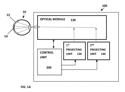
projection system. Reference is made together to Figs. 1A and 1B illustrating
schematically eye projection system 100 and method 250 for projection of an
image into
a user's eye according to some embodiments of the present invention. The eye
projection system 100 is configured to generate images and project the
generated
images into a user's eye 10. For simplicity, a single eye is shown in this
illustration;
however it should be understood that generally the image projections system
100 may
be configured to project images to both the user's eyes, while allowing
certain
differences between the right eye images and the left eye images, to provide
three
dimensional experiences.
Eye projection system 100 includes at least first 130 and second 140 image
projection units/modules (hereinafter also referred to as projection units),
and an optical
module 120 configured to direct light corresponding to images projected by the
projection units into the user's eye 10 to form images on the user's retina
12. The
system may generally also include, or be connectable to, at least one control
unit 200.
The control unit 200 is typically configured to render image data and transmit
it to be
projected by the first and second projection units 130 and 140.
To this end, rendering image data to be projected by the two or more (first
and
second) projection units 130 and 140 may include carrying out the operations
of method
250 as described forthwith. The control unit 200 may be configured and
operable for
carrying out operation 251 for receiving imagery data indicative of the
content of a
"projection image frame" (also referred to herein as combined image) that
should be
projected to the user's eye. The imagery data may, for example, include a
content and
layout of image(s) that should be projected onto the retina (where the content
may be
information of one or more images that should be simultaneously projected onto
the
retina, and the layout may include information about the arrangement/layout of
the
projection of these one or more images). The layout data may include for
example
lateral positioning data indicative of the lateral position of the image(s) on
the retina
(e.g. data about an anchor point in the image(s) representing a point of
intersection
between the LOS of the eye and the image plane). The control unit 200 may be
adapted
to carry out optional operation 252 for processing the imagery data to
determine/produce a "projection image frame" indicative of the combined
optical field
CA 03007069 2018-05-31
WO 2017/094002
PCT/1L2016/051275
- 15 -
(image content) that should be projected onto the retina. For instance, in
some cases the
"projection image frame" is formed by concatenating a plurality of images that
are
included in the image data, while arranging them in the frame in accordance
with the
layout data. In optional operation 253, the control unit performs a
registration operation
to register the "projection image frame" relative to the optical axis (LOS) of
the eye. In
other words, registration/alignment data indicative of aligned position of the
"projection
image frame" is relative to the LOS of the eye (e.g. registration/alignment
data may be
indicative of a point in the "projection image frame" which should be
intersected by the
LOS axis of the eye).
In operation 254, the control unit 200 segments the "projection image frame"
into two or more segments (image portions), which are to be projected by the
two or
more (first and second) image projection units, 130 and 140. At least one of
the image
projection units, e.g. 130, is adapted for projection of images (image
portions) onto the
central (foveal) region of the retina; and at least one other of the image
projection units,
e.g. 140, is adapted for projection of images (image portions) onto the
periphery
(parafoveal) region of the retina. Accordingly, in operation 254, the control
unit 200
utilizes the registration/alignment data obtained in 253 and segments the
"projection
image frame" into at least two image portions, which are to be respectively
projected by
the first and second image projection units, 130 and 140, onto the foveal and
parafoveal
regions of the retina. In this regard it should be noted that for carrying out
such
segmentation, the control unit may utilize projection unit configuration data
which is
indicative of the projection parameters, such as the numerical apertures
(NAs), of the
first and second image projection units, 130 and 140 (namely data about the
regions of
the retina which are covered by each of the projection units and their angular-
extents).
This allows the control unit 200 to properly segment and divide the
"projection image
frame" between image projection units, 130 and 140.
In 255 the control unit 200 carries out rendering of the first and second
image
portions that are to be projected by the image projection units, 130 and 140,
respectively. The control unit 200 may utilize the projection unit
configuration data,
which may be indicative of projection parameters such as angular resolution
and color
depths provided by the image projection units 130 and 140, to render the
respective first
and second image portions accordingly. In this regard, as indicated above, the
first
image projection unit 130, which is configured for projection of images to the
foveal
CA 03007069 2018-05-31
WO 2017/094002
PCT/1L2016/051275
- 16 -
region of the retina, may be configured for projecting images on the retina
with higher
angular resolution (higher DPI) and/or with improved color depth, than the
angular
resolution (DPI) and/or the color depth provided by the second of the image
projection
units, 140, which projects images on a parafoveal region of the retina. Then
in operation
256, the control unit provides rendering data indicative of the first and
second image
portions to the first and second image projection units, 130 and 140, for
projection
thereby. In this connection, the eye projection system 100 according to the
present
invention utilizes features of the anatomic structure of the human eye.
Reference is
made to Fig. 2 illustrating the anatomic structure of a human eye. As the
structure of the
human eye is generally known, it will not be described herein in detail, but
its suffices
to state that the retina (12 in Fig. 1) is the photosensitive region
collecting light and
generating data to be transmitted to the brain. The retina includes a
plurality of
photosensitive cells being sensitive to light intensity (black and white
vision) and to
wavelength (colour vision). More specifically, the retina includes rod type
cells (rods)
that are sensitive to luminosity (intensity of light) and cone type cells
(cones) that are
sensitive to chroma (colors or wavelengths). A region in the center of the
retina includes
greater concentration of cone cells (wavelength sensitive cells) and is known
as the
fovea (marked as 14 in Fig. 1). The fovea is in charge of providing detailed
images of
what is located at the center of the field of view, or the center of
attention. Generally the
foveal region provides higher spatial frequency or higher resolution, and
possibly higher
color sensing abilities, while the parafoveal region provides low resolution
image
perception (providing the brain with blurred indication on the periphery of
the scene)
and possibly lower color sensing abilities, while being more sensitive to
movement and
gradients within an input light field.
Accordingly, the image projection units 130 and 140 are configured and
operable for projection of complementary portions of the combined optical
field
("projection image frame") that is to be projected onto the retina. The first
image
projection unit 130 is configured and operable such that it can project a
first image
portion, which is to be directed to the foveal region of the retina, with high
image
projection quality (i.e. rendering/projecting the first image portion, such
that it has a
high angular resolution and/or high color depth). The second image projection
unit is
configured for projecting the second image portion (which is to be directed to
the
CA 03007069 2018-05-31
WO 2017/094002
PCT/1L2016/051275
- 17 -
parafoveal region of the retina, with lower image projection quality (i.e.
reduced angular
resolution and/or reduced color depth as compared to those of the first image
portion).
For instance the image projection unit 130 may be configured and operable for
projecting certain portion(s) of the projection image frame with high angular
resolution,
which is about or below 4 arc-minute2 of solid angle per pixel. The image
projection
unit 140 may be configured and operable for projecting certain portion(s) of
the
projection image frame with low angular resolution, which is about or above 10
arc-
minute2 of solid angle per pixel. In some embodiments the image projection
unit 130 is
configured for projecting its respective image portions with RGB color
contents (e.g.
with color depth of at least 8 bit (256 colors) or higher (e.g. 24bit)). The
image
projection unit 140, which is used for projecting images onto the periphery of
the retina,
may be configured for projecting its respective image portions with lower
color depths
(e.g. 4 bit color depth (16 colors)) and/or with no, or minimal, color
information (e.g.
gray scale image).
To this end, according to some embodiments of the present invention the image
projection unit 130 may be configured in a scanning image projection
configuration, (by
which an image is projected via scanning (raster scanning) a light beam
temporally
modulated with the image information, on the projection surface (namely on the
respective foveal region of the retina). Such scanning image projection
configuration of
the image projection unit 130 facilitates achieving high quality image
projections with
compact dimensions of the image projection unit 130. The image projection unit
140
may be configured in either a scanning image projection configuration; and/or
an aerial
image projection technique, e.g. which utilizes a spatial light modulator to
project its
respective image portions onto the parafoveal regions of the retina.
The optical module 120 is configured to combine image portions projected by
the at least first and second projecting units 130 and 140 and direct the
corresponding
light ray to form images projected into the user's eye 10 simultaneously.
Additionally,
the optical module is configured to direct images generated by different
projecting units
onto different regions (e.g. foveal and parafoveal regions) of the user's
retina 12.
In this regard, it should be noted that according to some embodiments of the
invention, in the segmentation operation 254 of method 250, the control unit
200
segments the "projection image frame" into two (or more) segments (first and
second
CA 03007069 2018-05-31
WO 2017/094002
PCT/1L2016/051275
- 18 -
image portions), which have some overlap along a boundary region between them.
Accordingly, in such embodiments, the first and second image projection units,
130 and
140, are configured and operable to project these first and second image
portions onto
the retina such that they overlap at the boundary area between them. Thus, on
the
boundary, similar image information is projected in an overlap and with
respectively
high and low image projection quality, by the first and second image
projection units
130 and 140. The optical module 120 may be configured to combine image
portions
generated by the first 130 and second 140 projection units such that the
overlap between
the first and second image portions is maintained. Further, the optical module
may be
configured and/or operable to direct the projected image portions such that
the boundary
between the image portions substantially corresponds to the anatomical
boundaries of
the fovea in the user's retina. The system may include a setting parameter
relating to
relative size/angular-extend of the foveal image and boundary location for
user's
selection, or may be fixed to fit the anatomy of a majority of users.
Overlapping
between image portions is typically provided to facilitate perceived smooth
transition
between the higher quality of the image projected on the foveal region of the
retina and
the lower quality of the image portions projected on the parafoveal region(s)
thereof,
and/or to compensate for inaccuracies and anatomical variations between users.
The control unit 200 may also be responsive to eye tracking data (e.g.
obtained
from an eye tracking module such as that disclosed in IL patent application
No. 241033)
on eye 10 orientation and/or position, and provide appropriate commands to the
optical
module 120 to vary the general path of image projection in order to correct
the optical
path of image projection in accordance with the eye's 10 movements. For
instance, the
optical module 120 may include a trajectory module (e.g. such as 124 shown in
Fig. 5)
which may include for instance an adjustable gaze tracking beam deflector
and/or an
adjustable pupil position beam deflector (e.g. which may be configured and
operable as
described in IL patent application No. 241033). The control unit 200 may be
configured
and operable for adjusting positions of one or both of these deflectors to
vary the
general propagation path of image projection in accordance with the gaze
direction
(direction of the LOS) of the eye, and/or the relative lateral displacement
and/or relative
angular orientation between the optical axis of the eye and the output optical
axis of the
optical module 120; e.g. to maintain substantially fixed relative orientation
and/or
displacement between them. Indeed, when fixed relative orientation and
displacement
CA 03007069 2018-05-31
WO 2017/094002
PCT/1L2016/051275
- 19 -
are maintained between the optical axis of the eye and the output optical axis
of the
optical module 120, the image(s)/image portions from the first 130 and second
140
projection units are projected at fixed location(s) on the retina.
Alternatively or additionally, in some embodiments, the control unit 200 may
be
configured and operable to compensate for some/slight changes/shifts in the
relative
orientation and/or displacement between the optical axes of the eye and the
optical
module 120, by operating the first and second projection units 130 and 140 to
shift
and/or warp the image projected thereby so that the projected optical field is
shifted/warped in ways that counteract changes in the relative
orientation/displacement.
For instance, use of such a technique to compensate for small eye movements is
exemplified in more detail below with reference to Fig. 6.
Thus, the eye projection system according to the present invention is
generally
configured to provide image projection with increased resolution to the foveal
region of
the retina, while providing image projection with relatively lower (e.g.
normal)
resolution to the parafoveal region surrounding the fovea. This enables the
system to
reduce complexity of image rendering/processing with respect to images of high
resolution, while providing high resolution images to regions of the user's
eye that will
actually utilize the high resolution image and require it.
Fig. 3 illustrates a two-portion image generated by the eye projection system
of
the invention. The complete image includes two image portions (generally at
least two
as the periphery image portion may be composed of several sub-images generated
by
several projection units) including the parafoveal/retinal image portion 1400
providing
peripheral image data, which generally surrounds the center of attention; and
the foveal
image portion 1300 providing the main part of the image data and which
corresponds to
the center of attention of the user. The foveal image portion 1300 may
typically be of
higher resolution with respect to the parafoveal image portion 1400. The
actual number
of pixels of the foveal portion 1300 and the parafoveal portion 1400 may be
the same or
higher. The difference in image resolution may typically be provided due to a
different
area (field of view) covered by each image portion. Specifically, the foveal
image
portion may generally be projected to cover the actual area of the fovea, or a
lightly
larger area, which is significantly smaller with respect to the surrounding
area of the
retina. It should be noted that the image portions as shown in Fig. 3
exemplify a circular
field of view. However, generally the field of view may be rectangular, oval
or of any
CA 03007069 2018-05-31
WO 2017/094002
PCT/1L2016/051275
- 20 -
other shape. The foveal region 1300 of the projected image may preferably be
of
circular shape or oval so as to cover the field of view of the fovea and thus
optimize the
sharp vision abilities of this region of the eye. Also exemplified in Fig. 3
is an angular
range of the foveal 1300 and parafoveal 1400 image portions at the user's
pupil.
Typically the angular range of the foveal image portion may be a lm and may be
between 30 and 10 , and preferably about 50. Additionally, the angular range
of the
parafoveal image portion at the pupil input may be higher than 20 , and
typically about
120 -1800
.
Referring to Fig. 4 and Fig. 5, two configurations of the eye projection
system
100 are shown, exemplifying more specific configurations of the optical module
120
according to two exemplary embodiments of the invention. As shown in Fig. 4,
the first
130 and second 140 projecting units are associated with corresponding initial
relay
modules 122a and 122b respectively. In the example of Fig. 5 the relay modules
are
combined to single relay module 122 including two (generally at least two)
input lenses
Lla and Llb and a single output lens L2. As shown in both the examples of Fig.
4 and
Fig. 5, the optical system 120 may preferably include a combining module (M or
M1
and M2), first 122 and second 126 relay modules and a tracking/trajectory
module 124.
In this connection, the first relay module, including separate relay modules
as in Fig. 4
or a combined relay module as in Fig. 5, is configured to merge image
projections
generated by the first 130 and second 140 projecting units (or additional
projecting units
being merged in parallel or in cascade) such that each projecting unit
transmits light to
form an image portion (i.e. an optical field) in a corresponding region along
a cross
section perpendicular to the general direction of propagation of projected
light.
Additionally, Fig. 4 illustrates output angular range amax of the first 130
and second 140
projecting units. As indicated, the first 130 and second 140 projecting units
may or may
not provide a similar output angular range. The optical system 120 is
configured to
adjust the angular range of each projecting unit as described in Fig. 3 above.
Referring to Fig. 4, each of the first 130 and second 140 projecting units
outputs
light indicative of an image or an image stream, marked in the figures by
extreme light
rays Rla, and Rlb for the first projecting unit 130, and R2a and R2b for the
second
projecting unit 140. The output light from the first projecting unit 130 is
transmitted into
input lens of relay module 122a and is relayed onto trajectory module 124.
More
CA 03007069 2018-05-31
WO 2017/094002
PCT/1L2016/051275
- 21 -
specifically, the light rays are output from the projecting unit such that
different pixels,
or different points on the projected image, are associated with corresponding
different
angles of light propagations. Thus the extreme light rays Rla and Rlb
correspond to
two extreme points on the projected image. First lens Lla of the relay unit
122a refracts
the light and directs it towards second lens L2a which re-focuses the input
light onto the
trajectory module 124. At the output of relay unit 122a, one or more beam
combiners,
M1 and M2 are located, as exemplified in the figure. The beam combiners M1 and
M2
are configured to combine light projected by the first projecting unit into
the optical
path of light projected by the second projecting unit 140. Similarly, relay
unit 122b
typically includes first and second lenses L2a and L2b and is configured to
relay light
projection from the second projecting unit 140 in a substantially similar
manner.
Exemplary light rays R2a and R2b illustrate the extreme light rays of
projection unit
140. Generally, the relay units 122a and 122b are configured with
appropriately
selected different optical powers of the lenses thereof and beam combiners M1
and M2
are located such that images projected by the first projecting unit 130 take a
smaller area
at a center of a region of image projection, surrounded by portions of images
projected
by the second projecting unit 140 as exemplified in Fig. 3. Further, it should
be noted
that generally both relay units 122a and 122b and the beam combiners M1 and M2
are
configured to merge the image portions to form a common image plane (e.g. on
the
trajectory unit 124). This is to ensure common focusing of the user's eye.
It should be noted that the relay unit 122a (as well as any other relay unit
such as
122b and 126, which is not specifically described here, may include additional
lenses
and are shown here as two-lens relay units for simplicity. It should also be
noted the
optical parameters of the relay units are selected to provide proper imaging
with desired
resolution and sharpness as generally known and/or can be determined by
standard
optical design tools.
The projected images generated by the first and second projecting unit 130 and
140 are directed onto the trajectory module 124. The trajectory module 124 may
include, for example, one or more moving light deflectors/mirrors (e.g. gaze
tracking
beam deflector and/or pupil position beam deflector as discussed above)
configured to
vary orientation thereof to direct light impinging thereon with a general
optical path
determined in accordance with tracking of eye movement. The trajectory module
124
and technique of eye tracking may be of any known configuration, and, as
indicated
CA 03007069 2018-05-31
WO 2017/094002
PCT/1L2016/051275
- 22 -
above, an exemplary configuration is described in IL patent application No.
241033
assigned to the assignee of the present application.
As indicated above, Fig. 5 illustrates an additional configuration of the
first
relay module 122, configured to combine projected images from the first and
second
projecting units 130 and 140 within the relay module. The relay module 122
utilizes a
common second lens L2 while utilizing separate first lenses Lla and Llb for
the first
130 and second 140 projection units. As shown, the output from the second
projecting
unit 140 is relayed through lenses Llb and L2 onto trajectory module 124.
Location and
optical power of lenses Llb and L2 is selected to provide angular distribution
of the
projected light (exemplified by extreme light rays R2a and R2b) to provide
desired
angular resolution for peripheral vision of the user. Light output of the
first projecting
unit 130, exemplified by extreme light rays Rla and Rib, is collected by input
lens Lla
converting the diverging light to a set of parallel light rays propagating
towards beam
combiner M. The beam combiner M, which, as indicated above, may utilize a
single
surface (e.g. reflecting surface) or a plurality of surfaces, or may be
configured as a
partially reflecting surface (e.g. beam splitter type), is configured to
direct output light
of the first projecting unit 130 to propagate with and be located at the
center of the cross
section of light output from the second projecting unit 140. Generally beam
combiner
M may be configured to block light transmission from the second projecting
unit 140,
within the region at the center of the cross section of the field of view.
However, in
some configurations, the beam combiner M may be configured to partially
transmit
light passing therethrough, and thus allow at least a portion of light
generated by the
second projecting unit 140 to pass at the center of the field of view. In some
further
embodiments, beam combiner M may block at a central region and transmit at the
periphery thereof, to allow smooth transition in image projection between the
image
generated by the first 130 and the second 140 projecting units. The combined
projected
light is further collected by second lens L2 and directed/focused onto the
trajectory
module 124.
In this connection it should be noted that the beam combining technique, i.e.
utilizing one, two or more beam combiners as in Figs. 4 and 5, may provide
certain
overlapping between image projection by the first projecting unit 130 (foveal
image)
and image projection by the second projecting unit 140 (parafoveal image). To
this end
the one or more beam combiners may be configured as beam splitting surfaces
CA 03007069 2018-05-31
WO 2017/094002
PCT/1L2016/051275
- 23 -
providing 50% reflection and 50% transmission of light, and/or as non uniform
beam
combiner surfaces having high transmission (reflection) at the periphery of
the surface
and high reflection (transmission) at the center of the surface. Thus, the
transition
between foveal image and parafoveal images may be made relatively smooth. It
should
also be noted that the graphic processing unit (GPU) may typically be
configured to
render the different image portions so as to provide smooth transition as
described
above. For example, the GPU may be configured to render images while adjusting
image brightness at image portion boundaries to avoid sharp gradients
resulting from
image combining.
Generally, according to the present invention as described herein with
reference
to Figs. 1, 4 and 5, the first and second projecting units, 130 and 140 may be
any type
of projecting unit, and may preferably be configured as scanning laser
projecting units.
Generally projection units of scanning laser type may provide greater
efficiency with
respect to light intensity, as well as in resolution of the projected images.
Typically, the
first and second projecting units 130 and 140 may be configured with similar
specification, while providing projection of different image data sent for the
control unit
(200 in Fig. 1) or Graphic Processing Unit (GPU) thereof. Although the optical
module
is configured to combine image projection of the first and second projecting
units (130
and 140) as generally exemplified in Fig. 3, the image data provided to the
second
projection unit 140 may be indicative of the complete image including the
central
(foveal) region, or it may include image data corresponding to a donut shaped
image
(i.e. peripheral image having a hole region where the image projected by the
first
projection unit 130 is combined).
As indicated above, the first and second projecting units (130 and 140) may
preferably be scanning laser type projection units. In such projection units,
a raster light
deflector (moving mirror, e.g. utilizing MEMS) is configured to scan a laser
beam
within an angular scanning range (angular projection range) amax. The optical
module
120 combines and directs the light of the at least first and second projecting
units such
that at the user's pupil, light generated by the first projecting unit has
angular range a lm
and light generated by the second projection unit has angular range a2m larger
than aim.
Effectively, different angles of light propagation at the user's pupil
correspond to
different points within the field of view. This is while angular resolution of
light
CA 03007069 2018-05-31
WO 2017/094002
PCT/1L2016/051275
- 24 -
projection generally corresponds to resolution of the perceived image. The
inventors
have found that based on the anatomy of the human eye, input angular range of
light
projection by the first projection unit aim is preferably configured to be
within a range
of about 30. In some configurations, the optical module 120 and the relay
module 126
thereof are configured to provide an angular range of about al-m=5 to ensure
coverage
of the foveal region within the retina. The angular range alin is preferably
determined in
accordance with image resolution provided by the first projection unit 130
such that
angular resolution at the input pupil of the user exceeds 2 arcminutes per
pixel, and
preferably exceeds 1 arcminute per pixel. Contrary to projection by the first
projecting
unit 130, light projection by the second projection unit 140 is generally
configured to
provide meaningful images within the periphery of the field of view. Thus, the
angular
range a2in associated with image projection by the second projecting unit 140
is
preferably greater than 200, and in some configurations may be greater than 70
to
provide the user image projection with a wide field of view and provide a
sense of
presence within the projected image. The second projection unit 140 may
provide a
similar number of different angular points, such that the larger the angular
range, the
lower the angular resolution.
When scanning laser type projection units are used, the laser beam may
generally include light beams from three or more laser units emitting three or
more
primary colors (e.g. red, green and blue) and is configured to vary intensity
of each of
the colors in accordance with the scanning orientation to provide imaging of a
desired
image data. The optical module 120 is configured to relay the light output
from the first
and second projection units such as to direct the projected light onto the
user's eye.
Generally the optical unit, and more specifically, the relay module 126
thereof is
configured to direct the input light into the user's eye such that a cross
section of the
light, at the user's pupil (i.e. eye-box) has a diameter smaller with respect
to the user's
pupil. More specifically, the cross section diameter of light (e.g. full
width, half max
measure, or standard deviation measure) is smaller with respect to pupil
diameter in
strong lighting conditions. This is while the trajectory module 124 deflects
the general
optical path to vary location and angle of the eye-box (exit pupil of the
system) in
accordance with detected gaze direction (LOS) and/or location of the pupil
(e.g. due to
eye/LOS movement relative to the eye projection system 100). It should also be
noted
CA 03007069 2018-05-31
WO 2017/094002
PCT/1L2016/051275
- 25 -
that output intensity of the projecting units, being scanning laser based on
non laser or
non scanning, and in some embodiments being spatial light modulator image
projecting
units (e.g. LCD based), is preferably sufficiently low, or is attenuated, to
avoid damage
and preferably avoid discomfort to the user.
In this connection it should be noted that the direct projection technique
used by
the optical module 120 according to the present invention provides for
projecting
images onto the eye retina, in a manner that the input light field propagates
to an image
plane on the retina. This is generally achieved regardless of focusing
distance/configuration of the user's eye (which is generally controlled based
on real or
virtual distance to objects of interest) as the eye-box size, or cross section
of the light
field at the pupil, is generally smaller than pupil diameter. This provides
image
projection with enhanced depth of focus on the retina. Accordingly, the image
is
projected to be substantially focused on the retina, at substantially any
focal state of the
eye lens. For example, the image may be projected with substantial depth of
focus
allowing it to remain focused on the retina, while the eye lens is at any
focal state within
a wide focal length range from 4 meters to 00.
Generally, according to some embodiments of the present invention, the eye
projection system as exemplified in Figs. 4 and 5, utilizes optical relay of
the projected
images into the user's eyes. In this connection, the technique of the present
invention
combines the projected images of the projection units (e.g. first and second
projection
units), and the combined light field passes through the trajectory module 124,
tracking
eye's movements, and are transmitted to the eye through relay module 126.
Thus, the
optical module 120 may be configured to optimize projection with respect to
eyes'
orientation, illumination conditions, image characteristics, user preferences
etc. This is
while the different image portions projection by the projection units are
combined to
direct image portions to the corresponding regions in the user's retina. As
indicated
above, in some embodiments of the invention, a first projection unit provides
image
projection directed towards the foveal region in the user's eye, while the
second
projection unit provides a surrounding image directed at the retina around the
fovea.
The projected images are combined using the one or more beam combiners and the
first
relay module(s). The latter is typically also configured to adjust spreading
of the
projected images such that the pixel density in the "foveal" image projected
by the first
projection unit is greater with respect to the pixel density in the
surrounding "retinal"
CA 03007069 2018-05-31
WO 2017/094002
PCT/1L2016/051275
- 26 -
image projected by the second projection unit. Generally the foveal image is
projected
with resolution corresponding to 480p 720p, 1080p or higher onto an angular
portion of
the field of view of about 30 to 50 to each direction. The parafoveal/retinal
image is
projected with a substantially similar number of pixels; however the projected
image is
relayed to the user's eye such that it takes a predetermined part of the
user's field of
view, while leaving the central region, corresponding to the foveal image as
shown in
Fig. 3, with low projection intensity to thereby allow projection of the
foveal image by
the first projecting unit 130.
Thus configuration of the optical module allows for adjustments of the exit
pupil
and of the general optical path in accordance with eye tracking and image
characteristics. It should also be noted that by providing high resolution
images directed
at the fovea with lower resolution peripheral image data, the system may
optimize the
experience while reducing computation complexity. Further, in order to
compensate for
small eye movement, the Graphic Processing Unit (GPU) associated with the eye
projection system, may be configured to render image data corresponding to a
region
that is slightly greater than the actual image data projected. Thus, the
rendered image
data exists and may be directly transmitted to the projection units based on
the exact
location of the eye at the time of projection. This is exemplified in Fig. 6
showing a
rendered region of the foveal 1300 and retinal 1400 images. More specifically,
while
image data corresponding to regions 1300 and 1400 is projected into the user's
eyes, the
GPU processes image data which corresponds to the following frame. The GPU
generated image data corresponds to regions 1310 and 1410, which are larger
than
regions 1300 and 1400. Regions 1310 and 1410 include image data that is
generally
outside of the field of view defined by image portions 1300 and 1400, referred
to herein
as shoulder image data. When, in the newly processed image, data is
transmitted to the
projection units (130 and 140), the control unit (200) indicates, using eye
tracking
technology, what is the exact location of the user's pupil, and the
corresponding parts of
the processed images are projected. This technique enables image variation
compensating for small eye movements by providing already rendered shoulder
image
data pieces. In this connection, providing high resolution (i.e. below 4 arc-
minute2 of
solid angle per pixel) to the foveal region of the user's eye in uniform
resolution
projection, requires generating image data having an extremely large amount of
pixels
CA 03007069 2018-05-31
WO 2017/094002
PCT/1L2016/051275
- 27 -
(full hemisphere image with such spatial resolution requires almost 30 Mega
pixels).
The technique of the present invention allows for providing image projection
with
desirably high perceived angular resolution, while reducing the image
resolution to
regions of the eye that are less sensitive. Thus the foveal image utilizes
high pixel
density providing angular resolution of below 4 arcminutes per pixel, while
the
parafoveal image provides lower angular resolution (e.g. about 10 arcminutes
per pixel).
This allows the control unit and the GPU thereof to generate image data
corresponding
to lower resolution images, e.g. about 5Mega pixels for foveal images and
5Mega pixels
for parafoveal images, providing a total rendered image data of about 10Mega
pixels.
Thus the present invention provides a system for image projection to a user's
eye. The system is configured to reduce image rendering complexity and data
transfer
from a processing/rendering unit to the projection unit(s), while providing
desirably
high resolution images to the user. The system is generally configured to
generate a
combined image projection based on two or more image portions directed at
corresponding portions of the user's retina, and is configured to optimally
exploit the
local sensitivity of the different regions of the retina. Those skilled in the
art will readily
appreciate that various modifications and changes can be applied to the
embodiments of
the invention as hereinbefore described without departing from its scope
defined in and
by the appended claims.