Note: Descriptions are shown in the official language in which they were submitted.
WO 2017/106608 PCT/US2016/067114
KNOTLESS SUTURE ANCHOR AND DEPLOYMENT DEVICE
CROSS REFERENCE TO RELATED APPLICATIONS
10001] This application claims priority to U.S. Provisional Patent
Application serial
number 62/268,028, which was filed on December 16, 2015.
BACKGROUND OF THE INVENTION
1. FIELD OF THE INVENTION
[0002] The present invention is related to anchors for securing
material to soft tissue and
bone and, more particularly, to suture anchors and suture anchor deployment
devices for
knotlessly securing filamentary materials, and soft tissue at a
surgical/repair site.
2. DESCRIPTION OF THE RELATED ART
[0003] Suture anchors are commonly employed during surgical procedures
to secure soft
tissue to bone. Such anchors are generally inserted into a pre-formed hole in
the bone ("pilot
hole"), so that a portion of filamentary material (e.g., suture
material/sutures) extends out of the
hole from the anchor and then the suture materials are passed through the
tissue to be repaired.
Once the tissue has been approximated to bone, the surgeon can tie one or more
knots to secure
the sutures. The act of tying a knot presents a number of challenges to the
surgeon especially
when doing them arthroscopically. See U.S. Pat. No. 8,409,252, col. 1, lines
24-41. Furthermore,
in some cases, knots have been implicated as the source of post-operative pain
caused by
irritation from the knot stack.
[0004] Various types of suture anchors have been developed which fasten
the suture in
place without requiring the surgeon to tie a knot. Typically, with respect to
these conventional
suture anchors, the suture is captured between two opposing surfaces and held
in place by
friction. Some designs capture the suture between two anchor components while
others utilize an
interference fit between the anchor and the bone tunnel. Provided the bone
quality is sufficient,
the latter method provides simplicity.
[0005] Description of the Related Art Section Disclaimer: To the extent
that specific
patents/publications/products are discussed above in this Description of the
Related Art Section
or elsewhere in this disclosure, these discussions should not be taken as an
admission that the
discussed patents/publications/products are prior art for patent law purposes.
For example, some
or all of the discussed patents/publications/products may not be sufficiently
early in time, may
1
CA 3007422 2019-11-26
WO 2017/106608 PCT/US2016/067114
not reflect subject matter developed early enough in time and/or may not be
sufficiently enabling
so as to amount to prior art for patent law purposes.
BRIEF SUMMARY OF THE INVENTION
100061 Embodiments of the present invention recognize that there are
potential problems
and/or disadvantages with the conventional suture anchors and their deployment
devices. For
example, adjusting and maintaining the proper suture tension can be difficult
and remains a
lingering problem. Therefore, the need exists for a simple to use suture
anchor which secures
suture without the need to tie a knot and which facilitates the ability to
adjust and maintain suture
tension during anchor installation. Various embodiments of the present
invention may be
advantageous in that they may solve or reduce one or more of the potential
problems and/or
disadvantages discussed herein.
100071 The present disclosure is directed to an inventive
configuration, structure, and
resulting function of a knotless suture anchor and the knotless suture
anchor's deployment
device. Various embodiments herein are directed to a cannulated implant
deployment device,
including, but not limited to: an elongated and cannulated driver shaft
extending along a
longitudinal axis including a proximal end and a distal end; a cannulated
implant removably
attached to the distal end of the driver shaft; a handle assembly connected to
the proximal end of
the driver shaft comprising a proximal handle and a knob positioned distally
to the proximal
handle; a cleat positioned on the driver shaft distally to the knob, wherein
the cleat is structured,
configured and positioned to secure a proximal end of a suture extending from
a distal end of the
implant, resulting in a first applied tension value of the suture extending
between the proximal
portion of the suture and a distal portion of the suture when the implant is
placed in a pilot hole
formed in a segment of bone tissue to secure the distal portion of the suture
within the pilot hole;
where each of the implant, proximal handle and cleat is connected to the
driver shaft such that an
axial rotation of the proximal handle in a first direction results in the
axial rotation of the implant
in the first direction and the maintenance of at least 50% of the first
applied tension value when
the implant is rotated in the first direction and advanced in the distal
direction within the pilot
hole.
2
CA 3007422 2019-11-26
CA 03007422 2018-06-04
WO 2017/106608 PCT/US2016/067114
[0008] According to an embodiment, the axial rotation of the proximal
handle in the first
direction results in the axial rotation of the implant in the first direction
and the maintenance of
about 100% of the first applied tension value when the implant is rotated in
the first direction and
advanced in the distal direction within the pilot hole.
[0009] According to an embodiment, the cleat is connected to the driver
shaft such that it
is configured to move in the distal direction away from the knob upon the
axial rotation of the
proximal handle in the first direction.
[0010] According to an embodiment, the cleat is connected to the driver
shaft such that it
is configured to move the same distance in the distal direction as the implant
is advanced in
the distal direction.
[0011] According to an embodiment, the implant contains external threading
extending
along at least a portion of an outside surface of the implant.
[0012] According to an embodiment, the driver shaft contains external
threading
extending along at least a portion of an outside surface of the driver shaft
and the knob contains
internal threading extending along at least a portion of an inside surface of
the knob, wherein the
external threading of the driver shaft mates with the internal threading of
the knob forming a
threaded interface, and the external threading of the driver shaft is
configured to move in the
distal direction in response to the axial rotation of the proximal handle in
the first direction.
[0013] According to an embodiment, the pitch of the external threading of
the implant is
about the same as the pitch of the external threading of the driver shaft.
[0014] According to an embodiment, the knob is not fixed to and is
configured to rotate
around the driver shaft.
[0015] According to an embodiment, the suture is positioned through the
driver shaft
from the distal end of the implant through an aperture formed in the side of
the driver shaft
between the proximal end and the distal end of the driver shaft to the cleat
on which it is secured.
[0016] According to an embodiment, the cannulated implant deployment device
further
comprises a suture threader positioned through the driver shaft from an
aperture formed in the
side of the driver shaft between the proximal end of the driver shaft and the
distal end of the
driver shaft through an opening in the distal end of the implant, wherein the
suture threader
comprises a suture catch positioned distally to the distal end of the implant
sufficient to capture a
portion of a suture.
3
CA 03007422 2018-06-04
WO 2017/106608 PCT/US2016/067114
[0017] According to an embodiment, the suture catch is formed as an eyelet.
[0018] According to an embodiment, the handle further comprises a locking
mechanism
configured to allow axial rotation of the handle in the first direction only.
[0019] According to an another aspect, a method of deploying a cannulated
implant into
a pilot hole formed in a segment of bone tissue includes (but is not limited
to) the steps of:
providing a cannulated implant deployment device including: an elongated and
cannulated driver
shaft extending along a longitudinal axis comprising a proximal end and a
distal end; a
cannulated implant removably attached to the distal end of the driver shaft; a
handle assembly
connected to the proximal end of the driver shaft comprising a proximal handle
and a knob
positioned distally to the proximal handle; and a cleat positioned on the
driver shaft distally to
the knob; securing a proximal end of a suture extending from a distal end of
the implant to the
cleat; inserting the implant into the pilot hole to secure a first distal
portion of the suture within
the pilot hole, and forming a first applied tension value of the suture
extending between the
proximal portion of the suture and the first distal portion of the suture; and
rotating the proximal
handle in a first direction to effectuate rotation of the implant in the first
direction and the
maintenance of at least 50% of the first applied tension value when the
implant is rotated in the
first direction and advanced in the distal direction within the pilot hole.
[0020] According to an embodiment, the step of rotating the proximal handle
in the first
direction results in the rotation of the implant in the first direction and
the maintenance of about
100% of the first applied tension value when the implant is rotated in the
first direction and
advanced in the distal direction within the pilot hole.
[0021] According to an embodiment, the step of rotating the proximal handle
in the first
direction results in the tensioning of a second distal portion of the suture
attached to a segment of
soft tissue and appositioning the segment of the soft tissue to the segment of
bone tissue.
[0022] According to an embodiment, the step of rotating results in the
movement of the
cleat in the distal direction away from the knob.
[0023] According to an embodiment, the step of rotating results in the
movement of the
cleat the same distance in the distal direction as the implant is advanced in
the distal direction.
[0024] According to an embodiment, the method further includes the step of
providing
the deployment device with a suture threader positioned through the driver
shaft from an aperture
formed in the side of the driver shaft between the proximal end of the driver
shaft and the distal
4
CA 03007422 2018-06-04
WO 2017/106608 PCT/US2016/067114
end of the driver shaft through an opening in the distal end of the implant,
wherein the suture
threader comprises a suture catch positioned distally to the distal end of the
implant.
[0025] According to an embodiment, the method further includes the steps of
capturing
the suture with the suture catch; and pulling the suture through the driver
from the distal end of
the implant through the aperture positioned between the proximal end of the
driver shaft and the
distal end of the driver shaft to the cleat on which it is secured prior to
the step of securing
[0026] According to a further aspect, a cannulated knotless anchor implant
is provided,
and can include: an elongated body extending along a longitudinal axis between
a proximal end
and a distal end; and a plurality of screw threads positioned about at least a
portion of an exterior
surface of the elongated body; where a density of the plurality of screw
threads varies along the
exterior surface.
[0027] Suture material or sutures, as the terms are used and described
herein, include
monofilament or multi-filament suture as well as any other metallic or non-
metallic filamentary
or wire-like material suitable for performing the function of a suture. This
material can include
both bioabsorbable and non-absorbable materials.
[0028] Knotless suture anchors/implants, as the terms are used and
described herein, may
be formed of a biocompatible and/or bioabsorbable material. These materials
may be of such
composition that they are reabsorbed by the body, e.g., during the healing
process of the bone.
Exemplary materials that are suitable for use in the inner and outer members
include, but are not
limited to, polyetheretherketone ("PEEK"), polylacti c acid/beta-tri calcium
phosphate
("PLA/Beta-TCP") composites, ultra-high molecular weight polyethylene
("UHMWPE"), as
well as other metallic, non-metallic, and polymeric materials.
BRIEF DESCRIPTION OF THE SEVERAL VIEWS OF THE DRAWING(S)
100291 The present invention will be more fully understood and appreciated
by reading
the following Detailed Description in conjunction with the accompanying
drawings, in which:
[0030] FIG. lA is a perspective view schematic representation of a knotless
anchor
deployment device with a cannulated knotless anchor implant according to an
embodiment;
[0031] FIG. 1B is a perspective view schematic representation of a distal
end of the
knotless anchor deployment device with a cannulated knotless anchor implant
shown in FIG. lA
according to an embodiment;
CA 03007422 2018-06-04
WO 2017/106608 PCT/US2016/067114
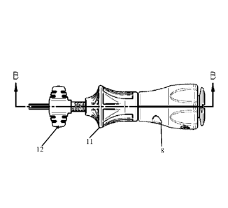
[0032] FIG. 1C is a side view schematic representation of a middle to a
proximal end of
the knotless anchor deployment device shown in FIG. lA according to an
embodiment;
[0033] FIG. 1D is a perspective view schematic representation of section B-
B of the
knotless anchor deployment device shown in FIG. 1C according to an embodiment;
[0034] FIG. 1E is a magnified perspective view schematic representation of
section "D"
of the knotless anchor deployment device shown in FIG. 1D according to an
embodiment;
[0035] FIG. 1F is a magnified perspective view schematic representation of
section "C"
of the knotless anchor deployment device shown in FIG. ID according to an
embodiment;
[0036] FIG. 2 is a flow chart showing a method according to an embodiment
of the
present invention.
[0037] FIG. 3 is a perspective view schematic representation of a distal
end of the
knotless anchor deployment device with a cannulated knotless anchor implant in
conjunction
with a segment of soft tissue and a segment of bone according to an
embodiment;
[0038] FIG. 4A is a perspective view schematic representation of a knotless
anchor
deployment device with a cannulated knotless anchor implant according to an
embodiment;
[0039] FIG. 4B is a magnified perspective view schematic representation of
section "A"
of the knotless anchor deployment device shown in FIG. 4A according to an
embodiment;
[0040] FIG. 5 is a perspective view schematic representation of a middle to
a proximal
end of the knotless anchor deployment device shown in FIG. 4A according to an
embodiment;
[0041] FIG. 6 is a perspective view schematic representation of a distal
end of the
knotless anchor deployment device with a cannulated knotless anchor implant in
conjunction
with a segment of soft tissue and a segment of bone according to an
embodiment;
[0042] FIG. 7 is a perspective view schematic representation of the segment
of soft tissue
secured to the segment of bone with the implant and suture according to an
embodiment.
[0043] FIG. 8 is a longitudinal sectional view schematic representation of
the implant
attached to the distal end of the driver shaft of the deployment device
according to an
embodiment.
[0044] FIG. 9 is a sectional view from the proximal end of a handle showing
a ratcheting
or locking mechanism within the handle according to an embodiment.
[0045] FIG. 10 is a perspective view of a cannulated knotless anchor
implant according
to an embodiment.
6
CA 03007422 2018-06-04
WO 2017/106608 PCT/US2016/067114
[0046] FIG 11 is a perspective view of a cannulated knotless anchor implant
according to
an alternative embodiment.
DETAILED DESCRIPTION OF THE INVENTION
[0047] Referring now to the drawings, wherein like reference numerals refer
to like parts
throughout, there is seen in FIG. 1A a knotless anchor deployment device 10
including an
elongated and cannulated driver shaft 2 extending along a longitudinal axis
comprising a
proximal end 4 (positioned within handle 8; shown in FIG. 1D) and a distal end
6 (positioned
within a cannulated knotless anchor implant 14). The cannulated knotless
anchor implant 14 is
removably attached to the distal end 6 of the driver shaft 2, and preferably
contains external
threading (but is not required to include the external threading). A handle
assembly is connected
to the proximal end 4 of the driver shaft 2, which includes a proximal handle
8 and a knob 10
positioned distally to the proximal handle 8. A cleat 12 is positioned on the
driver shaft 2 distally
to the knob 11. The cleat is formed of a central cylindrical portion 12-2
surrounding the driver
shaft 2 and two cleated winged portions 12-4 (see FIGS. 4A-4B). A suture
threader 16 can be
positioned through an aperture 18 (which can be a hole or a channel) formed in
a side of the
driver shaft 2 between the proximal end of the driver shaft and the distal end
of the driver shaft,
and can extend through an opening 20 in the distal end of the implant 14. The
threader 16 can
include a finger grip 22 attached to the proximal end of the threader 16 and a
suture catch 24
attached to the distal end of the threader, which can be positioned distally
to the distal end of the
implant 14 sufficient to capture a portion of a suture 26. The suture catch 24
as shown is shaped
like an eyelet. However, any shape or structural configuration that is
sufficient to capture a
portion of a suture 26 is contemplated.
[0048] Turning to FIG. 1C, a side view schematic representation of the
middle to the
proximal end of a knotless anchor deployment device shown in FIG. lA according
to an
embodiment is provided. The handle 8, knob 11 and cleat 12 are shown.
Referring to FIG. ID, a
perspective view schematic representation of section B-B of the knotless
anchor deployment
device shown in FIG. 1C according to an embodiment is provided. FIG. 1E shows
a magnified
perspective view schematic representation of section "D" of the knotless
anchor deployment
device shown in FIG. 1D according to an embodiment. Threads 46 are shown on a
portion of the
outer surface of the driver shaft 2, and threads 44 are shown on the inside of
the knob 11 forming
a threaded interface 48 with threads 46. A portion of the cleat 12 opposite
the threaded interface
7
CA 03007422 2018-06-04
WO 2017/106608 PCT/US2016/067114
includes a tooth 42 that engages a slot 40 formed in driver shaft 2, which
connects the driver
shaft 2 to the cleat 12. Referring to FIG. 1F, a magnified perspective view
schematic
representation of section "C" of the knotless anchor deployment device shown
in FIG. 1D
according to an embodiment is provided. A shaft 2/handle 8 interface 50,
similar to the tooth 42
that engages a slot 40 formed in driver shaft 2, is shown which connects the
driver shaft 2 to the
handle 8. The tooth 42/slot 40 connection between the cleat 12 and the driver
shaft 2 is
configured and/or structured to allow the cleat 12 to axially rotate with the
driver shaft 2. This
axial movement can occur upon the axial rotation of the handle 8, which is
configured and/or
structured to axially rotate the driver shaft 2 based on the shaft 2/handle 8
interface 50
connection.
[0049] In accordance with an exemplary embodiment, a method 200 of
deploying the
cannulated knotless anchor implant 14 with the knotless anchor deployment
device 10 into a
pilot hole 32 formed in a section of bone 30 is set forth in FIG. 2. The steps
of the method set
forth in FIG. 2 are discussed herein with reference to other Figures of this
disclosure. In step 202,
the free ends of a portion/length of a suture 26, which is passed through and
attached on one end
to a segment of soft tissue 28 (see FIG. 1B), is passed through the suture
catch 24. FIG. 1B also
shows a segment of bone 30 with a pilot hole 32 formed therein.
[0050] In step 204, the finger grip 22 of the suture threader 16 is pulled
in the proximal
direction, and the captured suture is pulled through the cannulated driver
shaft 2 from the
opening 20 in the distal end of the implant through the aperture 18 formed in
the side of the
driver shaft.
[0051] In step 206, the cannulated knotless anchor implant 14 is advanced
to the repair
site (pilot hole 32), while suture 26 slack is continued to be pulled through
the driver shaft 2
from the opening 20 in the distal end of the implant through the aperture 18
formed in the side of
the driver shaft to bring the segment of soft tissue 28 in close proximity to
the distal tip of the
cannulated knotless anchor implant 14 and to the pilot hole 32 (see FIG. 3).
[0052] In step 208, a proximal end of the suture 26 is secured to the cleat
12 by
wrapping, for example, to either winged cleated portion of the cleat (see
FIGS. 4A-4B), and the
distal tip of the cannulated knotless anchor implant 14 is subsequently
inserted into the pilot hole
32 pinning a distal portion of the suture between the implant 14 and the pilot
hole 32. This step
can result in a first applied tension value of the suture extending between
the proximal portion of
CA 03007422 2018-06-04
WO 2017/106608 PCT/US2016/067114
the suture (attached to the cleat 12) and the distal portion of the suture
(within the pilot hole 32),
when the implant is placed in the pilot hole 32 to secure the distal portion
of the suture within the
pilot hole 32. Rotation of the handle 8 can assist with the creation of the
first applied tension
value (which is a tension that is greater than an initial tension value, which
can be generally
loose suture which contains some "slack", as should be appreciated by a person
of skill in the art
in conjunction with a review of this disclosure), and to bring the segment of
soft tissue 28 to
apposition with bone. Alternatively, rotation of the knob 11 in one direction
(e.g.
counterclockwise) can extend the cleat 12 axially and distally away from the
knob 11, and
rotation of the knob in a second direction (e.g., clockwise) can bring the
cleat 12 closer (move
axially and proximally) to the knob 11, thereby reducing or adding to the
tension value
respectively. This axial movement of the cleat (and the driver shaft 2
attached to the cleat 12) can
assist in fine tuning the creation and maintenance of the applied tension
value without the
corresponding rotation of the cleat 12 and driver shaft 2 (due to the knob's
configuration with
respect to the driver shaft, as it is preferably not fixed to the driver shaft
2 in the same manner as
the cleat 1 and the handle 8).
[0053] In step 210, the handle 8 is axially rotated in a first direction
(e.g., clockwise; see
FIG. 5), and the deployment device 10 is advanced in the distal direction. The
rotation of the
handle 8 in the first direction results in the axial rotation of the shaft 2
and the cleat 12 in the first
direction (due to the configuration etc. discussed above). This rotation also
results in the axial
rotation of the implant 14 in the pilot hole 32 (based on its connection to
the distal end of the
driver shaft 2), and assists with the advancement of the implant 14 in the
distal direction into the
pilot hole 32. The knob 11 is preferably held in place when the handle 8 is
axially rotated, and is
preferably not connected, configured, and/or structured to positively rotate
in the first direction
in the same way as the driver shaft 2 and the cleat 12 (i.e., it is not fixed
to the driver shaft 2). If
the knob 11 is not held in place, the knob 11 may axially rotate a small
amount in the first
direction based on a frictional engagement with other parts of the deployment
device 10, but not
at the same rate etc. as the handle 8, driver shaft 2, and cleat 12.
[0054] Per the axial rotation of the handle 8 in the first direction, at
least 50% (and up to
about 100%) of the first applied tension value is maintained when the implant
14 is rotated in the
first direction and advanced in the distal direction within the pilot hole (as
long each end of the
suture remains secured ¨ to the cleat and within the pilot hole,
respectively). In accordance with
9
CA 03007422 2018-06-04
WO 2017/106608 PCT/US2016/067114
an embodiment, a percentage of the first applied tension value is maintained
based on the cleat
being configured to move in the distal direction away from the knob 8 upon the
axial rotation of
the handle 8 in the first direction. Upon the axial rotation in the first
direction, the cleat 12 is
connected to the driver shaft 2 such that it is configured to move the same
distance in the distal
direction away from the knob 8 as the implant 14 is advanced in the distal
direction within the
pilot hole 14. This distal direction movement can be accomplished via the
configuration of the
external threading 46 on the driver shaft 2 (as described above), which forms
a threaded interface
48 with the internal threading of the knob 8 and is configured to move in the
distal direction in
response to the axial rotation of the handle 8 in the first direction.
Preferably, the pitch of the
external threading of the implant 14 is about the same or exactly the same as
(corresponds to) the
pitch of the external threading 46 of the driver shaft 2. The cleat 12 and the
implant 14 each
axially rotates in the first direction and translates distally at a rate
corresponding to the pitch
when the handle 8 is rotated to advance the implant 14 into the pilot hole 32.
[0055] Notably, if the suture 26 were held stationary and not allowed into
the pilot hole
32, the implant 14 could be damaged, over tension the segment of soft tissue
28 leading to tissue
incarceration or cause it to auger out the pilot hole 32. If the suture 26 was
not held (or if there
was otherwise no or low tension maintained in the suture, as described) there
would be a
possibility of losing tension and tissue apposition to bone resulting in a bad
repair.
[0056] In step 212, the implant 14 is advanced until its proximal end is
flush with the
bone 30 surface (see FIG. 6).
[0057] In step 214, the suture can be removed from the cleat 12, the
implant 14 can be
deployed, and the driver shaft 2 can be removed from the repair site (see FIG.
7). The driver
shaft 2 is pulled free from the implant 14 positioned within the pilot hole
32, leaving the implant
1 within the pilot hole 32. As shown in FIG. 8, the implant 14 is attached to
the distal end 6 of
the driver shaft 2 via a friction fit. The lumen 2-2 of the driver shaft 2
within the lumen of the
implant 14 is shown, and the lumen 14-2 of the implant without containing a
portion of the driver
shaft is also shown. The distal tip of the driver shaft 2 contains a
cylindrical portion which is
sized to create a slight interference with the cannulation of the implant 14.
For example, a
stepped interface 52 between the lumen of the distal portion of the distal end
of the driver shaft 2
and the lumen of the implant 14 is provided. This stepped interface 52 or
additional stepped
interfaces can exist in different positions between the lumen of the driver
shaft 2 and the implant
CA 03007422 2018-06-04
WO 2017/106608 PCT/US2016/067114
14. Another purpose of the stepped interface is to help prevent the driver
shaft 2 from extending
distally beyond the implant 14 during deployment. The force of the friction
fit is preferably less
than the force of the fit between the implant 14 and the pilot hole 32,
allowing the deployment
device to be easily removed from the implant 14 and the pilot hole 32 after
the implant 14 is
deployed within the pilot hole 32. The excess suture can be trimmed flush with
the bone surface
completing the repair.
[0058] In some embodiments (see FIG. 9), the handle 8 can further include a
ratcheting
or locking mechanism including a round gear 54 with teeth and a biased, spring
loaded/cantilevered finger 56 configured to allow axial rotation of the handle
8 (and thus, the
driver shaft 2, the cleat 12, and the implant 14) in the first direction only.
As a user rotates the
handle in the first (clockwise) direction, the distal end of the finger 56
moves from fitting
between one set of teeth to a second set of teeth on the round gear 54 - where
the round gear 54
is locked from moving in the opposite (counterclockwise) direction. This
configuration
preferably ensures that the tension is maintained during manipulation and
placement of the
implant 14 into the pilot hole 32. The ratcheting or locking mechanism can
include any type of
mechanism which does not allow axial rotation in one direction, as should be
appreciated by one
of skill in the art in conjunction with a review of this disclosure.
[0059] Turning to FIG. 10, a perspective view of a cannulated knotless
anchor implant 14
in accordance with an embodiment is shown. The cannulated knotless anchor
implant 14 can
include an elongated body extending along a longitudinal axis between a
proximal end 14-4 and
a distal end 14-6. The cannulated knotless anchor implant 14 can also include
a screw thread 14-
8 positioned about the exterior surface of the knotless anchor implant 14. The
screw thread 14-8
can be continuous or non-continuous, where each revolution or apparent
revolution around the
elongated body can be deemed a separate screw thread creating a plurality of
screw threads (even
though screw thread 14-8 may be continuous). The screw thread 14-8 can extend
(1) from the
most proximal portion of the proximal end to the most distal portion of the
distal end, (2) from
the most proximal portion of the proximal end to a position prior to the most
distal portion of the
distal end, (3) from a position between the most proximal portion of the
proximal end and the
most distal portion of the distal end to another position between the most
proximal portion of the
proximal end and the most distal portion of the distal end, or (4) any
combination of the
foregoing positions (or any other position on the exterior surface of the
exterior portion of the
11
CA 03007422 2018-06-04
WO 2017/106608 PCT/US2016/067114
cannulated knotless anchor implant 14). The screw threads 14-8 can be
positioned all the way
around the exterior surface of the cannulated knotless anchor implant 14,
partially around the
exterior surface of the cannulated knotless anchor implant 14 (e.g., 1/4, 1/2,
3/4, of the way around),
or can include a combination thereof Additionally, a density of a number of
screw threads can
vary along the exterior surface of the cannulated knotless anchor implant 14.
For example, the
density of the number of screw threads 14-8 positioned about the exterior
surface of the
cannulated knotless anchor implant 14 can be greater between the proximal end
14-4 and about
half way towards the distal end 14-6 as compared to the density of the number
of screw threads
14-8' positioned about the exterior surface of the knotless anchor implant 14
between about half
way towards the distal end 14-6 and the distal end 14-6. Further, the lumen 14-
2 of the
elongated body can comprise more than one diameter, e.g., the proximal end 14-
4 can include a
larger diameter than the distal end 14-6. This difference in diameter size can
be based on
differences in shape between sections of the elongated body (e.g., conical vs.
different sized
cylindrical sections), or the narrowing or enlargement of the size of the
lumen at any given point
along the longitudinal axis based on changes in the thickness of the interior
wall sections of the
elongated body.
[0060] Turning to FIG. 11, a perspective view of a cannulated knotless
anchor implant
14' in accordance with an alternative embodiment is shown. The majority of the
features of
cannulated knotless anchor implant 14' are similar to the cannulated knotless
anchor implant 14.
However, cannulated knotless anchor implant 14' also includes at least one
laterally positioned
hole 14-12, which is substantially transverse to the lumen 14-2. A suture 26
is shown positioned
through the hole 14-12. The laterally positioned hole or holes 14-12 can be
positioned through
one portion of the exterior surface or through two portions of the exterior
surface, which can be,
but do not need to be, directly across from each other, and can be next to
each other.
[0061] While embodiments of the present invention has been particularly
shown and
described with reference to certain exemplary embodiments, it will be
understood by one skilled
in the art that various changes in detail may be effected therein without
departing from the spirit
and scope of the invention as defined by claims that can be supported by the
written description
and drawings. Further, where exemplary embodiments are described with
reference to a certain
number of elements it will be understood that the exemplary embodiments can be
practiced
utilizing either less than or more than the certain number of elements.
12