Note: Descriptions are shown in the official language in which they were submitted.
CA 03007440 2018-06-05
WO 2017/108697
PCT/EP2016/081755
CLOSURE
Background of the Invention
Numerous personal care products are sold in plastic bottles. Examples of such
products are body washes and shampoos. While dispensing of a body wash or hair
care
product from a bottle is convenient for the consumer, plastic bottles
generally are
disposed of after one use and sometimes undesirably find their way into
landfills.
Although plastic bottles are sometimes recycled, both transportation to the
recycling
facility and recycling itself utilize energy. Accordingly, it would be
preferable if the
packaging were re-used instead of discarded after a single use.
While some present commercial bottles could theoretically be re-used by
consumers, the ease of doing so generally leaves something to be desired. For
instance, it may be difficult for a consumer to remove the closure
sufficiently to facilitate
access to the body of the bottle. This creates a considerable impediment to
the goal of
minimization of plastic usage and disposal. Therefore, there has been a need
for a
bottle having a closure which can readily be removed by the consumer.
Moreover, it is
important that the consumer be able easily to again secure the closure to the
bottle
once she has refilled the container.
Easy consumer access to the interior of the bottle is certainly desirable, but
the
bottle cannot be designed such that the closure will separate from the bottle
too readily.
Otherwise, product will be released from the container at inopportune times,
such as
during transportation. Also, the goal of a readily separable closure must be
balanced
with a competing goal, namely ease of placing the closure on the bottle during
manufacture and attendant minimization of production costs.
Jackel US Patent No. 8,365.933 discloses a closure system including a snap-on
closure which can be pressed upon a spout wherein two interacting elements are
1
CA 03007440 2018-06-05
WO 2017/108697
PCT/EP2016/081755
shifted by or over one another due to their flexibility. The closure can only
be removed
with difficulty in the axial/vertical direction by exerting a certain force,
but can be
removed by a rotational motion which is significantly easier to perform than
the axial
removal motion. The closure includes a recess in a cylindrical snap-on pipe
which
engages with a forcing element on the container shoulder. The sides of the
recess are
designed so that the gradient at one point on one side is smaller than the
gradient at the
same point on the other side.
Summary of the Invention
The present invention is directed to an improved snap-on/twist off closure
which
does not suffer from some disadvantages of prior closures. In particular, it
is very
durable, as can be seen in the standard industry drop test. The invention is
also
directed to a package comprising the closure, e.g., a bottle in combination
with the
closure.
The base of the closure of the invention includes an upper wall defining an
opening and a cylindrical snap-on pipe depending from the upper wall and
extending
vertically/axially to a bottom pipe end. The cylindrical snap-on pipe includes
threads on
an inner wall designed to mate with external threads on a neck of the bottle.
The closure
base is snap fit onto the bottle neck whereby the thread of the cylindrical
snap-on pipe
passes over and temporarily locks beneath the thread of the container neck.
The closure cylindrical snap-on pipe includes at its bottom end at least one
resistance recess and at least one guidance recess. The resistance and
guidance
recesses play roles in the unscrewing of the closure whereby it can be easily
removed
for refilling. The resistance recess includes opposing first and second walls
defined by
the cylindrical snap-on pipe and which have gradients wherein the gradient of
one of the
walls is smaller at least at one point than the gradient on the other wall at
a point lying at
the same axial/vertical height.
2
CA 03007440 2018-06-05
WO 2017/108697
PCT/EP2016/081755
When the closure is closed, a forcing element from the container is at least
partially accommodated within the resistance recess. The resistance recess
wall with
the higher gradient contacts the forcing element, which resists turning of the
closure in
one (non-opening/screwing closed/closure securing) direction, usually the
clockwise
3.0 direction. When the closure is turned in the opposite, or
opening/unscrewing/closure
removal direction, contact between the gentler gradient of the opposite wall
of the
resistance recess and the forcing element forces the closure upwardly. The
flexible
nature of the closure material and/or the flexibility in the snap-on pipe
attributable to the
presence of the recesses in the pipe permit the internal threads on the
cylindrical snap-
on pipe to pass over the external threads of the container neck as the closure
travels
axially upwardly relative to the container neck.
Upon further turning of the closure in the counterclockwise or
unscrewing/opening direction, the forcing element encounters the trailing end
of the
resistance recess followed by the bottom rim of the snap-on pipe and then by a
guidance recess. During rotation of the closure in the unscrewing/opening
direction, the
guidance recess first extends upwardly from the bottom end to help to lower
the
cylindrical snap-on pipe relative to the container neck so that the mating
threads on the
closure cylindrical snap-on pipe and container neck contact each other.
Thereafter, with
the cylindrical snap-on pipe and neck threads in engagement, as the closure is
rotated
further in the unscrewing/opening/closure removal direction, the guidance
recess
includes a gradual downward gradient toward the bottom end of the cylindrical
snap-on
pipe.
The downward gradient of the guidance recess, and resultant relative upward
motion of the closure consistent with the gradients of the matching threads on
the
container neck and skirt, provides guidance and offers minimal resistance to
turning of
the closure in the unscrewing/opening direction. The consumer can continue
turning the
closure with minimal resistance whereby to eventually remove the closure. The
3
CA 03007440 2018-06-05
WO 2017/108697
PCT/EP2016/(181755
presence of the guidance recess also facilitates the reverse process wherein
the
consumer rotates the closure in the closing, usually clockwise, direction
after having
refilled the bottle.
The closure may include a closing element which contacts and/or covers the top
wall of the closure base to seal the closure opening, but which can be removed
from the
opening to dispense the product. Preferably the closing element remains
associated
with the closure base when removed to dispense the product, e.g., as the
result of a
hinge or other attachment.
The bottom rim of the snap-on pipe extending between the resistance recess
and the guidance recess is preferably at least 2mm and is up to 5mm,
especially from 2
to 4 mm, in length whereby to maximize durability of the closure, including
promoting a
good, comfortably tight, fit of the closure on the bottle over a prolonged
period of use.
The closure of the invention permits secure placement of a closure on the
bottle
neck during manufacture yet easy removal of the closure from, and re-
application of the
closure to, the bottle by the consumer, thereby encouraging removal of the
closure to
refill the container. The closure is durable, e.g., is resistant to wear and
tear.
It will be apparent that changes such as the directions of screwing/unscrewing
and the locations of the threads may require adjustments in the locations and
shape of
the resistance and guidance recesses.
For a more complete understanding of the above and other features and
advantages of the invention, reference should be made to the following
detailed
description of preferred embodiments and to the accompanying drawings.
Brief Descriptions of the Drawings
4
CA 03007440 2018-06-05
WO 2017/108697
PCT/EP2016/081755
Fig. 1 is a side elevational view of the bottle and closure of the invention
with the
closure in cross section
Fig. 2 is a front elevational view of a bottle of the invention with a portion
of the
neck cut away and showing the closure base above it in cross section with the
closing
cover removed.
Fig. 3 is a perspective view from above of a closure according to the
invention in
the open position.
Fig. 4 is a bottom plan view of the closure of Fig. 3.
Fig. 5 is a side elevation of the package of the invention with the closure
partly
rotated in the unscrewing/opening/closure removal direction and with portions
of the
closure broken away to reveal the cylindrical snap-on pipe.
Fig. 6 is a side elevational view of an upper portion of the container with
portions
of the closure broken away and with the closure in the fully closed position.
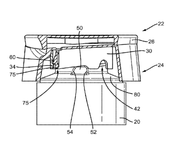
Fig 7 is a side elevational view of the closure with portions broken away.
Detailed Description of the Invention
Closure 22 sits on bottle 20 (Figs. 5 and 6). Closure 22 includes closure base
24
connected to closing cover 26 by hinge 28, although other possible
arrangements will
be apparent to one of ordinary skill in the art. Closure base 24 includes
generally
cylindrical snap-on pipe 30, best seen in Figs. 1 and 2, depending downwardly
from
upper wall 25. Cylindrical snap-on pipe 30 is positioned to engage neck 32 of
bottle 20.
The inner wall of cylindrical snap-on pipe 30 includes one or more internal
threads 34,
which protrude inwardly.
5
CA 03007440 2018-06-05
WO 2017/108697
PCT/EP2016/081755
Closure base 24 includes a dispensing opening 36 centrally disposed within
upper wall 25. Although opening 36 is illustrated and described as being
centrally
disposed, it may be off-center if desired. Structure may be provided above
and/or
below opening 36 to assist with pouring or sealing, such as ring 38. When
closure base
24 is positioned on bottle 20, opening 36 is in communication with the
interior of bottle
20 through the interior of snap-on pipe 30 and exterior closure base wall 23.
Closing
cover 26 includes plug 40 to assist in sealing the bottle.
Neck 32 of bottle 20 includes external threaded protrusion 60.
As best seen in Figs. 5-7, cylindrical snap-on pipe 30 includes resistance
recess
42 extending upwardly from bottom end or rim 43. Rim 43 typically extends
perpendicularly to the downwardly extending axis of the pipe. A second
resistance
recess 42a may be present 180 removed from resistance recess 42, as seen in
Fig. 1.
Resistance recess 42 includes two walls 44, 46 formed in cylindrical snap-on
pipe 30.
The shape of walls 44. 46 will depend upon the direction which it is desired
to have the
closure rotate in order to release it from the bottle so that it can be
removed.
Typically, closures are unscrewed/opened/removed by turning counterclockwise,
so for the purpose of the present description counterclockwise
unscrewing/opening will
be assumed. However, it will be apparent that a different direction could be
used if
desired and the shapes of walls 44, 46 and the location of guidance recess 70
will be
adjusted accordingly.
As best seen in Fig. 6, when the closure is in the closed position, resistance
recess 42 receives at least part of forcing element 50. which is a protrusion
permanently
associated with bottle shoulder 80.
The trailing resistance recess wall during unscrewing/opening rotation,
illustrated
as 44 in Fig. 7, includes at its lower end 45 a gradient which is more gradual
than that of
6
CA 03007440 2018-06-05
WO 2017/108697
PCT/EP2016/081755
the opposite (leading) recess wall 46; the gradient at the lower end of
resistance recess
wall 46 is more severe or steep. The forcing element 50 also includes two side
walls 54,
52 of different gradients.
Starting from the initially closed position shown in Fig. 6, if the closure is
rotated
in the clockwise direction as the consumer turns it, a steep gradient of
forcing element
side wall 52 faces a steep gradient on resistance recess wall 46 and prevents
rotation.
On the other hand, upon rotation of the closure in the counterclockwise
direction from
the initially closed position, side wall 54 of the forcing element having a
gentler gradient
faces resistance recess wall 44 which has a gentler gradient in its lower
half, e.g., at 45,
proximate its base. The effect of this contact between walls of gentler
gradients is that,
instead of prevention of rotation, which occurs with the steeper gradients,
the forcing
element 50 forces the walls of the resistance recess and the depending
cylindrical snap-
on pipe 30 upwardly.
The smaller, gentler gradient at 45 (Fig. 7) of the resistance recess wall 44
is
similar or identical to the gradient of side wall 54 of the forcing element of
the
container, which faces resistance recess wall 44 during unscrewing/opening.
The
gradient of wall of 44 at section 45 is within the range of between 10 degrees
more and
10 degrees less than that of wall 54. Thus, if wall 54 is 45 degrees, wall 44
at section
45 is within the range of from 35 degrees to 55 degrees. Each of wall 44 and
54 is
within the range of between 30 and 85 degrees. The gradient of wall 44 at
section 45
is measured relative to a horizontal line drawn through rim section 56. The
gradient of
wall 54 is measured at the point at which it first contacts wall 44 upon
rotation and is
measured with respect to a horizontal line intersecting the point of contact
with wall 44,
the line being parallel to, or coincident with, bottom rim section 56.
Further counterclockwise rotation of closure 22 during removal of the closure
by
the consumer will result in forcing element 50 clearing resistance recess wall
44, and
7
CA 03007440 2018-06-05
WO 2017/108697
PCT/EP2016/081755
the top 58 of the forcing element contacting section 56 of bottom rim 43 of
the cylindrical
snap-on pipe. Upon still further unscrewing/opening, counterclockwise,
rotation of
closure 22, top 58 of forcing element 50 encounters guidance recess 70, seen
e.g., in
Fig. 7. Guidance recess 70 includes an upwardly extending wall 72 at a
gradient within
the range of 90 and 135 degrees to a horizontal line drawn through section 56
of the
bottom rim and then a downwardly extending wall 74 at a less severe gradient
of within
the range of 0 to10 degrees relative to a horizontal line drawn through the
intersection
75 of wall 74 and pipe bottom 43.
The distance between resistance recess 42 and the guidance recess 70 is
measured along bottom rim section 56 from the point at which wall 44 merges
with snap
on pipe bottom end or rim 43 to the point at which guidance recess wall 70
begins to
ascend at the beginning of wall 72. The distance between the resistance recess
and
the guidance recess in the unscrewing/opening direction is preferably at least
3mm.
The distance is typically from 2mm up to 5mm, especially from 2mm to 4mm.
The presence of the guidance recess in addition to the resistance recess also
facilitates rotation of the closure in the opposite, closing, direction, which
is generally
clockwise. When the closure is rotated in the clockwise, closing direction, at
point 75
(Fig. 5), forcing element 50 encounters gradually upwardly sloping wall 74 of
guidance
recess 70, then the steeper, downward slope of wall 72, then rim 43 at section
56 and
finally resistance recess wall 44 and steep wall 46.
In operation, during manufacture of the package, closure 22 is snap fit onto
neck
32 (e.g., Fig. 2) of bottle 20 by closure 22 being pressed axially downwardly
(or bottle
20 being pressed axially upwardly, or both). Since the bottle body and the
closure are
made of a flexible material and/or because the presence of one or more
recesses in the
pipe permits the cylindrical snap-on pipe 30 to expand resiliently radially,
the internal
thread 34 on the cylindrical snap-on pipe passes over the external thread 60
on the
container neck and the closure snaps onto the neck. Thus, the closure is
securely
8
CA 03007440 2018-06-05
WO 2017/108697
PCT/EP2016/081755
attached to the container and a substantial amount of effort would be needed
for the
consumer or other external force to separate them using a vertical or upward
motion.
Alternatively, closure 22 may initially be applied onto container 20 by being
rotated on,
to engage the threads.
In normal use, the product is dispensed with cover 26 removed from opening 36.
Cover 26 is then closed so that plug 40 seals the opening when the product is
not in
use.
When the bottle is substantially empty of the shampoo, body wash, lotion or
other
product originally contained within, the consumer removes closure 22 from the
package
to facilitate refilling and reusing it. To remove the closure, the consumer
rotates it,
typically in the counterclockwise direction, starting from the position shown
in Fig. 6.
When forcing element 50 forces closure 22 upwardly upon closure rotation as
described
above, cylindrical snap-on pipe thread 34 is forced past container neck thread
60.
Thread 34 is able to pass container neck thread 60 since the cylindrical snap-
on pipe is
able to expand radially due to the presence of the recesses and/or due to the
flexible
nature of the material of which the cylindrical snap-on pipe is fabricated.
Forcing element 50 next encounters section 56 of bottom rim 43 of the
cylindrical
snap-on pipe and then upwardly extending wall 72 of guidance recess 70. The
latter
permits the cylindrical snap-on pipe axially to lower itself toward the
container neck,
which in turn permits cylindrical snap-on pipe thread 34 to lie on thread 60
whereupon
the consumer can continue to use a normal rotation to unscrew the closure from
the
container neck. Fig. 5 shows forcing element 50 within recess 70. This
unscrewing
rotation is further facilitated by forcing element top 58 contacting
downwardly extending
wall 74 of guidance recess 70. Contact by the top 58 with downwardly extending
wall 74
raises the closure cylindrical snap-on pipe to support the normal unscrewing
action of
the closure, whereby the closure is easily removed. The pitch of the threads
is similar
to the gradient of wall 74.
9
CA 03007440 2018-06-05
WO 2017/108697
PCT/EP2016/081755
With the closure removed, the consumer then refills the bottle with the
shampoo
or other product. She then applies the closure back onto the bottle either by
snapping
the closure downwardly over the bottle neck in an axial direction similar to
that used in
manufacture, or she screws the closure back on to the bottle neck. If she
chooses the
latter, the clockwise-moving rim 43 of pipe 30 contacts top 58 of forcing
element 50.
When it reaches point 75 (Fig. 5), it encounters gradually ascending wall 74
which
contact results in a lowering of the pipe relative to the bottle neck
consistent with the
normal screwing downwardly of a closure.
When the forward and/or top wall of the forcing element encounters wall 72 of
guidance recess 70, pipe 30 is raised relative to bottle neck 32 and the top
58 of forcing
element 50 contacts section 56 of rim 43. Upon further rotation, forcing
element
reaches resistance recess wall 44 and pipe 30 moves downwardly as forcing
element
50 is accommodated within recess 42. As the consumer further rotates the
closure and
the pipe moves downwardly, internal thread 34 of pipe 30 is forced past
external thread
60 on bottle neck 32 whereby to snap the closure onto the bottle neck. When
forcing
element wall 52 encounters steep wall 46 of resistance recess 42 the closure
cannot be
rotated any further.
The closure can be placed on the container neck securely and economically by
vertical/axial placement on the bottle during manufacture, whereas by
providing the
consumer with the ability readily to rotate the closure for removal and to re-
apply it to
the bottle, refilling of the container is promoted. Closure 22 may be also be
applied onto
the container during manufacture by being rotated to engage the threads.
References to upward or downward motion herein assume that container 20 is
resting on its base (not shown) at its end opposite the closure.
CA 03007440 2018-06-05
WO 2017/108697
PCT/EP2016/081755
The closure may be made from polypropylene and the bottle can be molded from
high-density polyethylene or polypropylene. The closure is designed to be
durable,
resisting normal wear and tear by opening and closing the closure and even by
dropping.
It should be understood, of course, that the specific forms of the invention
herein
illustrated and described are intended to be representative only as certain
changes may
be made therein without departing from the clear teachings of the disclosure.
Accordingly, reference should be made to the following appended claims in
determining
the full scope of the invention.
11