Note: Descriptions are shown in the official language in which they were submitted.
- 1 -
VERSATILE FURNITURE ITEM
DESCRIPTION
Field of the invention
The present invention relates to a motorized furniture item, configured to
assume
a plurality of different configurations.
io Background of the invention
Nowadays, the need for transformable and versatile furniture items is strongly
felt, due to more and more people living or working in environments of limited
size.
Such need is felt particularly when an environment is intended for several
is destinations of use, for example as a living room and a dining room, and
when a
variable number of people should be received into it. In fact, depending upon
the
different destinations of use and number of people, chairs, beds and sofas
need
to be alternatively put in, and removed from, the available environment.
However,
moving furniture can be hard to be managed in practice. Moreover, it implies a
20 significant waste of time and a relevant risk of damaging the furniture
or the
surrounding environment.
Moreover, even when only one or few people occupy a given environment, a full
furnishing requires having a sofa, a bed, a chair and eventually a chaise
longue
as separate pieces.
Summary of the invention
The technical problem underlying the present invention is therefore that of
overcoming the drawbacks mentioned above with reference to the state of the
art.
Such problem is solved by a motorized furniture item as described herein.
The furniture item according to the present invention is able to transform and
adjust its configuration in a simple and effective way. Moreover, it is
conceived
as a module of a furnishing assembly. When taken alone or in such assembly,
Date Recue/Date Received 2022-03-18
CA 03007445 2018-06-05
WO 2017/115390 PCT/IT2015/000324
2
he furniture item(s) transforms, for example, from chair or stool to sofa,
rmchair, "triclinio" (triclinium), chaise longue or bed, depending upon
specific
requirements and needs.
herefore, the furniture item of the invention provides a plurality of
unctionalities into a single object. As it will be appreciated also from the
= etailed description that follows, its destination of use can be simply
and quickly
hanged, even without the need for additional components.
dvantageously, the furniture item according to the invention allows optimizing
113 he use of space.
rief description of the drawings
Reference will be made to the figures of the annexed drawings, wherein:
¨ Figure 1 shows a perspective view of a motorized furniture item according
to a preferred embodiment of the present invention, in a stool configuration;
¨ Figures 2 shows a perspective view of the furniture item of Figure 1 in a
chair configuration;
¨ Figure 3 shows a perspective view of two furniture items according to the
embodiment of Figure 1, which are joined to implement a bed configuration;
¨ Figure 4 shows a perspective view of the furniture items of Figure 3 in a
chaise longue configuration;
¨ Figure 5 shows a perspective view of the furniture items of Figure 3 in a
triclinium configuration;
.. - Figures 6 and 7 each show a respective perspective view of two furniture
items according to the embodiment of Figure 1, which are joined to
implement a sofa configuration;
¨ Figure 8 shows a schematic perspective view taken from above of inner
components of the furniture item of Figure 1, according to a preferred
implementation;
¨ Figure 8A shows a schematic frontal view of a detail of the furniture
item of
Figure 8;
¨ Figure 9 shows schematically a perspective view of inner components of
the furniture item of Figure 1, according to a preferred implementation;
- Figure 10 shows schematically a perspective view of a detail of the
furniture
item of Figure 9;
¨ Figures 11 and 11A each show a schematic perspective view of a detail of
a
mechanism of the furniture item of Figure 9, in a lowered and a raised
position, respectively; and
CA 03007445 2018-06-05
WO 2017/115390 PCT/IT2015/000324
3
¨ Figure 12 shows a block diagram of a preferred embodiment of a controlling
scheme of the furniture item of Figure 1.
Detailed description of preferred embodiments of the invention
ith reference initially to Figures 1 and 2, a preferred embodiment of a
otorized furniture item according to the present invention is globally denoted
ley 1.
=s will be appreciated in the following, the furniture item 1 is capable of
to .ssuming a plurality of different configurations.
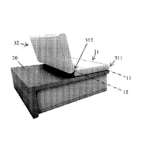
In Figure 1, a stool configuration of the furniture item 1 is shown. In Figure
2, a
hair configuration of the furniture item 1 is depicted.
he furniture item 1 comprises a main body 2 and first and second movable
=odies, respectively denoted by 31 and 32, which are capable of receiving and
,upporting a user's body.
Preferably, the main body 2 has a substantially polyhedral shape, in
particular a
parallelepiped shape. The main body 2 has four lateral (vertical) sides, one
of
hich defined by a lateral wall 22. The main body 2 has also a bottom
horizontal wall 21 apt to be rested on the floor and an upper horizontal
+ upporting wall 20. Both walls 20 and 21 are substantially rectangular in
plan
iew.
Preferably, (part of) the exterior surfaces of the main body 2 are lined with
natural wood panels and leather.
Furthermore, the main body 2 provides, between its bottom wall 21 and its
,upporting wall 22, a housing 100 for an extractable table unit 5. The housing
100 is accessed at three sides of the main body 2, i.e. the sides not having
the
lateral wall 2.
= s visible in Figures 4 and 5, the table unit 5 can be prismatic shaped,
in the
present example with a rectangular basis.
he table unit 5 comprises a first basic member 52, in particular box-shaped,
hich houses telescopically, or slidably, a second raisable member 53. The
upper raisable member 53 preferably has the same shape of the basic member
52, but reduced overall dimensions so that it can be housed therein.
he second member 53 has a support surface 50 which is suitable to bear
=bjects. In particular, the support surface 50 is useful for reading, eating
and, in
=eneral, for supporting objects needed during activities performed while
sitting
= r lying on the furniture item 1.
he second member 53 is selectively movable upwards/downwards. In
CA 03007445 2018-06-05
WO 2017/115390 PCT/IT2015/000324
4
=articular, the extractable table unit 5 is configured so that it can assume a
first
inimal-encumbrance arrangement, wherein it is housed inside the main body
, and a second operative, or use, arrangement, wherein it is extracted from
the
am n body 2.
n the stool configuration of Figure 1, the upper supporting wall 20 supports
the
eight of both the movable bodies 31 and 32 and the user received thereon.
he first and second movable bodies 31 and 32 are arranged side by side upon
he upper face of the supporting wall 20, in particular along a longitudinal
= irection L of main development of the furniture item 1. The longitudinal
drection L is also the direction according to which a user rests upon the
urniture item 1, corresponding to the user's body height.
In the embodiment described, the movable bodies 31 and 32 are prismatic
-haped, with a rectangular basis.
In the present embodiment, the movable bodies 31 and 32 have substantially
he same shape and overall dimensions.
he first movable body 31 is rotatably connected, at a first end side 311
thereof,
o the main body 2 and can accordingly rotate about a first horizontal rotation
=xis 11.
he second movable body 32 is rotatably connected to the first movable body
41 at a second end side 312 of the latter, which second end side 312 is
=pposite to the first end side 311. So, the second movable body 32 can
.ccordingly rotate about a second horizontal rotation axis 12, parallel to the
first
rotation axis 11.
Preferably, the lateral side of the main body 2 at which the extractable table
unit
is provided is a side perpendicular to the rotation axes 11 and 12, so that
the
able 5, in use, is arranged laterally with respect to the user.
Preferably, the surface extension of the movable bodies 31 and 32 is such that
hen they are superimposed and lay upon the upper supporting wall 20 in the
tool configuration, they cover substantially all the upper supporting face 20.
A dvantageously, each of the first and second movable body 31, 32 can have a
ushion-like, or pad-like covering, for a more comfortable sitting and resting,
preferably with a fabric or leather lining.
he furniture item 1 preferably comprises connection means 9 configured for a
removable attachment to one or more other equal furniture items, as shown by
ay of example in Figure 3. The connection means 9 can be provided at every
lateral side of the main body 2, so that there is no limit to the number of
items
can be connected together. The connection means 9 can be of electromagnetic
ype, in particular realized by means of an electromagnetic plate system. To
CA 03007445 2018-06-05
WO 2017/115390 PCT/IT2015/000324
onnect/disconnect the items it is simply necessary to push a button, which
nverts the module polarity of the system and makes the items be
oined/separated by virtue of the electromagnetic attraction/repulsion force
=etween the systems provided by each item.
5 n particular, Figure 3 shows a perspective view of two furniture items
according
o the described embodiment, joined according to a first attachment
onfiguration which realizes a bed configuration.
n the configuration shown, the furniture item 1 is connected to another
equal
tern 1' at a contact plane parallel to the rotation axes 11 and 12.
n addition, such attachment configuration allows the assembly to realize a
haise longue configuration and a triclinium configuration, shown in Figures 4
Ind 5, by adjusting the reciprocal inclination of the two movable bodies 31
and
c 2.
n Figures 4 and 5, the extractable table unit 5 in the use arrangement is
also
isible. In the embodiment shown, an additional service surface 51 is provided,
= referably having substantially the same width of the support surface 50
so that
t can also lie superimposed to the latter. The additional service surface 51
is
=ivotally connected to the support surface 50 according to a pivot axis 13, in
= articular an axis perpendicular to the support surface 50, preferably a
vertical
1 xis. The additional service surface 51 is useful for providing a support
moved
:way or approachable to the user by a simple rotation.
A second attachment configuration of two furniture items 1 and 1' according to
he embodiment herein described is shown in Figures 6 and 7. As can be seen,
he furniture items can be attached at lateral sides perpendicular to the
rotation
xes 11 and 12, thus realizing a sofa configuration.
o pass from one configuration to another one, the first and second movable
=odies 31 and 32 are actuated to rotate about the first and second horizontal
otation axes 11 and 12 by driving, or actuation, means 4 which are shown in
igures 8, 9, 10 and 12. Preferably, the driving means 4 includes a plurality
of
inear and/or rotational actuators or motors housed inside the main body 2 and
It least one of the movable bodies 31 and 32.
= s shown schematically in Figure 12, the driving means 4 are commanded by
a
ontrol unit 400, the latter in communication with a user interface 444.
In particular, the driving means 4 moves, directly or through the
interposition of
ransmission or actuation means, an articulated supporting structure 40
eceived inside the first and second movable bodies 31 and 32.
he overall arrangement is such that it is possible to adjust the position of
each
movable body 31, 32 with respect to the other one and to the main body 2. In
particular, the inclination of the first movable body 31 with respect to the
main
CA 03007445 2018-06-05
WO 2017/115390
PCT/IT2015/000324
6
=ody 2 can be selected according to specific needs.
urthermore, independently from the just mentioned position/inclination of the
irst movable body 31, the inclination of the second movable body 32 with
espect to the first movable body 31 can be selected as well, and consequently
.. he global positioning of the second movable body 32 with respect to the
main
= ody 2 can be chosen.
aking reference to Figure 2, it can be seen an example of regulation of the
nclination of the second movable body 32 with respect to the first movable
body
Cl and the main body 2, so as to realize a chair configuration.
he articulated supporting structure 40 and the operation mode of the driving
eans 4 will be now described in detail.
preferred embodiment of an articulated supporting structure 40 is shown in
igure 9. Preferably, the structure 40 comprises a polygonal frame, comprising
= first and a second frame portions 41 and 42, each following the
(rectangular)
=erimeter of a respective movable body 31, 32 and joined at second rotation
:xis 12. The frame portions 41, 42 can comprise also reinforcing rods,
-xtending perpendicular to, and in general inclined versus, the rotation axes
11
nd 12, as visible in Figure 9. The first frame portion 41 is received inside
the
irst movable body 31 and it is rotatably connected at its proximal end 411 to
a
.upport structure 200 of the main body 2 according to rotation axis 11.
he first frame portion 41 is rotatably connected at its distal end 421 to the
.econd frame portion 42 according to second rotation axis 12, in particular by
= ivotal connections as shown in Figure 9.
he second frame portion 42 is received inside the second movable body 32.
he frame portions 41 and 42 rotate about the rotation axes 11 and 12
integrally
ith the movable bodies 31 and 32.
s shown in Figure 8, the aforementioned support structure 200 of the main
.. =ody 2 comprises a polygonal frame, having rods developing along the edges
of
he lateral sides of the main body 2. The structure 200 is preferably made of
etal and comprises facilities for housing the driving means 4 and associated
.upply means which will be shortly.
ith reference to Figure 10, the driving means 4 preferably comprises also rods
of the movable bodies 31, 32, and low voltage electric motors (or equivalent
ctuators), each located in a respective housing integral to the support
structure
Po 00 and/or the first frame portion 41 and/or the second frame portion 42.
The
rrangement is such that rotation of the motors determines a relative rotation
of
he movable bodies 31, 32.
CA 03007445 2018-06-05
WO 2017/115390 PCT/IT2015/000324
7
Furthermore, the motors are coordinated by a dedicated circuit which balances
-ach change of position of the movable part of the furniture item 1. In
particular,
he absolute and relative position of the movable bodies 31 and 32 can be
ontrolled directly by the user and/or according to predetermined movement
=rogrammes pre-stored in the control unit 400.
Preferably, the driving means 4 also comprises means for moving the table unit
according to a sliding movement of insertion/extraction within/from the main
=ody 2. In variant embodiments, such movement could be also manually
= perated.
uch means preferably comprises hydraulic and/or pneumatic cylinders
-xtending along the extraction direction of the table 5, having a first
terminal
-nd fixed to the support structure 200 and a second terminal end fixed to the
easic member 52. In the configuration shown in Figure 10, a cylinder 14 is
,hown which is in a configuration of maximum extension and the table unit 5 is
-xtracted from the main body.
In Figures 11 and 11A, a mechanism 550 housed within the basic part 52 of the
able unit 5 is shown. The mechanism 550 is in particular a lifting mechanism,
preferably a pantograph-line mechanism, configured to move the raisable
member 53 according to a sliding movement along a vertical direction of
insertion/extraction in/from the basic member 52. The mechanism 550
omprises a plate member 551 fixed over a lower part of the basic member 52,
having at two opposite sides a rectilinear slot 552 configured to allow the
insertion of an arm 554, 555 at a first end thereof and the sliding of such
arm.
he arms 554, 555 are pivotally connected at a second end thereof to
respective supporting bars 556, 557, configured to support the upper raisable
part 53. To pass from the first rest configuration of Figure 11 to the
extracted
onfiguration of Figure 11A, and vice-versa, the first ends of the arms 554,
555
slide along the slots 552 and the second ends of the arms pivotally rotate
with
respect to th 556, 557, so that the bars and the upper raisable part 53 do not
change their inclination during the extraction movement.
Both the insertion/extraction movement and the raising/lowering movement of
he table unit 5 can be commanded through the user interface 444. In
particular,
he furniture item 1 can be configured in such a way that by pressing a single
button, or operative control, both movements are actuated in an automatic
sequence, either for extracting and raising the table unit 5 or for (re-
)storing it
inside the main body 2.
Figure 8A shows one of a plurality of wheels 8 of the furniture item 1, which
are
CA 03007445 2018-06-05
WO 2017/115390 PCT/IT2015/000324
8
dvantageously provided in order to allow an easy displacement thereof.
Preferably, each wheel 8 is housed within the main body 2, at a bottom portion
hereof. Each wheel 8 is associated with a respective spring, or contrast,
- lement 81 so as to assume an exposed position, shown in Figure 8A, wherein
he wheel contacts the ground, and an hidden position, wherein the wheel is
eacted inside the main body 2. Spring elements 81 can be calibrated so that
he respective wheels contact the ground only when a person, or, generally
-peaking, a load, is not received upon the furniture item 1.
to he furniture
item 1 according to the present invention preferably comprises the
Iforementioned control unit 400 of the driving means 4, as shown in Figure 12.
he control unit 400 can be connected by connecting means or networks (e.g.
: luetooth or Internet) to the remote interface 444, which can be implemented
as
1 stationary or mobile device (e.g. mobile phone or tablet, pc). By means of
the
is nterface 444
is possible to control the movements of item 1 and choose a
-pecific configuration thereof. By the interface 444 is it possible both to
insert
'referable inclination values relative to the movable bodies 31, 32 and/or a
'referable extraction position of the table 5 and/or to choose particular pre-
set
=ositions or configurations pre-stored in storage means of the control unit
400.
dvantageously, the furniture item 1 according to the invention can comprise
echargeable supply means, as a rechargeable Lithium-Ion battery. The battery,
hich is easily to pull out and charge in his charger, makes possible the item
1
an be moved or transported without moving or disconnecting electrical cables.
he present invention has been described so far with reference to preferred
-mbodiments. It is intended that there may be other embodiments which refer to
he same inventive concept and fall within the scope of the appended claims.