Note: Descriptions are shown in the official language in which they were submitted.
CA 03007514 2018-06-06
WO 2017/097853
PCT/EP2016/080127
INTERLEAVED BEAM PATTERN FOR SONOTHROMBOLYSIS AND OTHER
VASCULAR ACOUSTIC RESONATOR MEDIATED THERAPIES
FIELD OF THE INVENTION
This disclosure relates to medical ultrasound systems and, in particular, to
ultrasound systems which perform sonothrombolysis and other therapy in
combination with
vascular acoustic resonators (VARs), such as gas-filled microvesicles.
BACKGROUND OF THE INVENTION
Ischemic stroke is one of the most debilitating disorders known to medicine.
The blockage or significant reduction of the flow of blood to the brain can
rapidly result in
paralysis or death. Attempts to achieve recanalization through thrombolytic
drug therapy
such as treatment with tissue plasminogen activator (tPA) has been reported to
cause
symptomatic intracerebral hemorrhage in a number of cases. Advances in the
diagnosis and
treatment of this crippling affliction are the subject of continuing medical
research.
US Pat. 8,211,023 (Swan et al.) describes a diagnostic ultrasound system and
method which enable a clinician to transcranially visualize a region of the
cerebral
vasculature where blood clots may be present. Either two dimensional or three
dimensional
imaging may be employed. The imaging of the vasculature is preferably enhanced
by the
administration of VARs. If the flow conditions of the vasculature indicate the
presence of a
partial or complete occlusion from a blood clot, a focused or pencil beam of
ultrasound is
directed to the location of the blockage to break up the clot by the
vibrations and/or rupturing
of the VARs. In some instances the ruptured VARs may also release an
encapsulated
thrombolytic drug. The patent also describes monitoring the cranial
vasculature by ultrasonic
imaging for changes which are indicative of the recurrence of an occlusion so
that medical
aid can be alerted to the recurrent condition.
In order for the ultrasound to effectively break up or lyse a blood clot, it
is
important for the ultrasound to uniformly and completely insonify the location
of the clot-
induced blood flow arrest or reduction, and to effectively use the VARs at the
locus of the
clot and the relevant region of interest surrounding it to break up the clot
as rapidly and
thoroughly as possible. The region of interest may be as small as the clot,
i.e. when clearly
identified or of several cubic centimeters when clot is suspected but not
clearly identifiable or
CA 03007514 2018-06-06
WO 2017/097853
PCT/EP2016/080127
2
localizable. In order to achieve sufficient ultrasound amplitude for the
desired therapeutic
effect, application of focused ultrasound is generally preferred. However,
because of the
relatively small surface area of focused ultrasound beam, the focused beam
must be steered
throughout the region of interest for adequate clot treatment. Focused
ultrasound beam area is
characterized by a peak beam pressure and a beam width at which the lateral
pressure is half
the peak beam. Therefore, VARs are subjected to different ultrasound pressure
according to
their location with regards to the peak pressure of the ultrasound beam
pattern. At low to
modest acoustic pressure of 50-100kPA, VARs gradually disappear due to gradual
escape of
the gas from the VAR's envelope. But when VARs are exposed to sufficient
acoustic
.. pressure amplitude to have a therapeutic effect, typically 200-400 kPa,
VARs envelope is
destroyed rapidly but remain active for sonothrombolysis (typically for
several tens of
milliseconds) as long as they continue to remain in the ultrasound field. As a
consequence,
for sufficient acoustic beam pressure VARs will be efficient at the beam peak,
but VARs near
the beam will disappear gradually. This disappearance of VARs away from the
center of a
.. beam area occurs at lower ultrasound amplitudes which do not effectively
contribute to the
therapeutic effect. Accordingly it is desirable to limit or prevent such
disappearance (or
ineffective destruction) of VARs, so that the clot lysis will occur as rapidly
and effectively as
possible.
It is an object of the present disclosure to improve the effectiveness of
sonothrombolysis through more effective use of the VARs at the site of a blood
clot. It is a
further object of the disclosure to allow the replenishment of VARs which are
ineffectively
destroyed adjacent to the lysing beam center.
In some aspects, the present disclosure includes methods and systems for
insonifying a region of interest, e.g., a therapy region. For example, the
present disclosure
includes methods and systems for insonifying a therapy region containing VARs
with
ultrasound therapy beams. The methods can include and the systems can be
configured for
transmitting a first pattern of ultrasound therapy beams through the therapy
region, the beams
being separated from each other by a predetermined spacing between the beams,
and
transmitting a second pattern of ultrasound therapy beams through the therapy
region, the
beams being directed to the spaces which separate the beams of the first beam
pattern from
each other. According to an aspect, the spacing between the beams of the first
(and preferably
subsequent patterns) leaves residual VARs between the beams.
In certain aspects, the methods can include and the systems can be configured
for refraining from transmitting during a time interval between the different
patterns, e.g.,
CA 03007514 2018-06-06
WO 2017/097853
PCT/EP2016/080127
3
between each pattern to allow VAR replenishment at the therapy region. The
time intervals
can include a predetermined amount of time ranging, e.g. at least greater than
0.1 seconds,
from 0.1 to 20 seconds, from 0.5 to 10 seconds, from 1 to 2 seconds, and from
1 to 5 seconds.
The methods can include and the systems can be configured for transmitting
other patterns, such as transmitting third and fourth patterns of ultrasound
therapy beams
having the same beam patterns as the first and second beam patterns and being
offset by an
interbeam spacing between the ultrasound therapy beams. Transmitting of the
third and
fourth patterns of ultrasound therapy beams can further include transmitting a
third beam
pattern of the same pattern as the second beam pattern, and transmitting a
fourth beam pattern
of the same pattern as the first beam pattern, the ultrasound therapy beams
being offset by an
interbeam spacing.
In general each beam is characterized by a peak beam pressure (and power)
and by respective beam widths at which the corresponding lateral pressure is a
percentage of
the peak beam pressure or power. For instance, beam widths can be identified
as having a
lateral pressure of 18.25-25% or half (50%) of the peak beam pressure, refered
herein as a
half pressure beam width; also, beam widths can be identified as having a
lateral pressure of
about 70% of the peak beam pressure, which also corresponds in general to the
beam width at
half power peak beam, refered herein as a half prower beam width. In certain
aspects,
transmitting a pattern of ultrasound therapy beams can include transmitting
beams where the
respective beam centers are separated from each other by a spacing which is at
least equal to
the half power peak beam width (corresponding to a beam width at about 70% of
peak beam
pressure). In other aspects, transmitting a pattern of ultrasound therapy
beams can include
transmitting beams separated from each other by a spacing which is at least
equal to half
(50%) pressure beam width. In some aspects, transmitting a pattern of
ultrasound therapy
beams can include transmitting beams separated from each other by a spacing
which is not
greater than the 18.75% - 25% pressure beam width. The transmitting of a
pattern of
ultrasound therapy beams can include transmitting beams separated from each
other by a
spacing, which, e.g., can in certain embodiments range from 2.6 to 5.2 mm.
In certain aspects, transmitting a first pattern of ultrasound therapy beams
can
include transmitting a pattern of beams which are separated from each other
horizontally and
vertically. The transmitting a second pattern of ultrasound therapy beams can
also include
transmitting a pattern of beams which are spatially interleaved horizontally
and vertically
between the beams of the first pattern, and transmitting a third pattern of
ultrasound therapy
CA 03007514 2018-06-06
WO 2017/097853
PCT/EP2016/080127
4
beams which are spatially interleaved horizontally and vertically between the
beams of the
first and second patterns.
In certain aspects, the methods can include and systems can be configured for
transmitting a first pattern of ultrasound therapy beams in which beams are
separated from
each other horizontally and vertically. The methods can include and systems
can be
configured for transmitting a second pattern of ultrasound therapy beams in
which beams are
spatially interleaved diagonally between the beams of the first pattern. Also,
the methods can
include and systems can be configured for transmitting a third pattern of
ultrasound therapy
beams which are spatially interleaved horizontally and vertically between the
beams of the
first and second patterns, and transmitting a fourth pattern of ultrasound
therapy beams which
are spatially interleaved horizontally and vertically between the beams of the
first and second
patterns.
In some aspects, the present disclosure can include ultrasound systems for
insonifying a therapy region and configured to carry out the methods disclosed
herein. For
instance, the present disclosure can include an ultrasound system having
instructions thereon,
which when executed, cause the system to transmit a first pattern of
ultrasound therapy
beams through a therapy region, the beam areas being separated from each other
by a
predetermined spacing, which under some circumstances can leave residual VARs
between
the beams, and transmit a second pattern of ultrasound therapy beams through
the therapy
region, the beams being directed to the spaces which separate the beams of the
first beam
pattern from each other. In other embodiments, the present disclosure can
include a region
containing VARs with spatially interleaved patterns of ultrasound beams. The
system can
include a two dimensional (2D) array (for example, a phased 2D array) of
ultrasonic
transducer elements, and a transmit controller coupled to the transducer array
to
electronically steer therapy beams into the therapeutic region. The transmit
controller can be
configured to cause the transducer array to (1) transmit a first pattern of
ultrasound therapy
beams through the therapy region, the beams being separated from each other by
predetermined spaces and (2) transmit a second pattern of ultrasound therapy
beams directed
to the spaces separating the beams of the first beam pattern from each other.
In particular the
predetermined spaces between the beams of a pattern are such that the lateral
beam lower
ultrasound pressure would leave a certain amount of the VARs which are within
said spaces
substantially unaffected. In certain aspects, the transmit controller can be
configured to cause
the transducer array to refrain from transmitting for a refresh interval
between transmission
of the first and second pattern. The transmit controller can also be
configured to cause the
84264548
transducer array to transmit a third pattern of ultrasound therapy beams which
are spatially
interleaved between the beams of the first and second beam patterns, and/or to
cause the
transducer array to transmit a fourth pattern of ultrasound therapy beams
which are spatially
interleaved between the beams of the first and second beam patterns.
5 In one embodiment, the present disclosure provides an ultrasound system
for insonifying
a region of interest containing vascular acoustic resonators (VARs) with
spatially interleaved
patterns of ultrasound beams comprising: an ultrasound array arranged to
transmit ultrasound
therapy beams into the region of interest, the therapy beams having beam areas
with a peak beam
pressure which is sufficient to destroy VARs in the region of interest; and a
transmit controller
coupled to the array and arranged to electronically control steering of the
therapy beams in a
plurality of sequential patterns of beams separated by a beam spacing which,
in consideration of
the peak beam pressure, leaves residual VARs between adjacent beams after beam
transmission,
wherein a subsequent in time pattern comprises beam areas which are spatially
interleaved
between beam areas of a previous pattern so as to destroy residual VARs.
BRIEF DESCRIPTION OF THE DRAWINGS
FIGURE 1 illustrates in block diagram form an ultrasonic system constructed in
accordance with the principles of the present disclosure.
FIGURES 2 illustrates regions of the cranium which can be treated by
transducer arrays
located over the temporal bone on either side of the head.
FIGURE 2a illustrates a cranial headset suitable for holding transducer arrays
in acoustic
contact with the temporal bone regions of the head.
FIGURE 3 is a graphic illustration of the pressure thresholds of a typical
ultrasound
beam.
FIGURES 4a, 4b, and 4c are cross-sectional illustrations of blood clots
following
different applications of different sequences of ultrasonic therapy beams.
FIGURES 5 a to 5 d illustrate four ultrasonic therapy beam patterns in
accordance with
the principles of the present disclosure; figure 5e illustrates the
superposition of the four patterns
of figures 5a to 5d.
FIGURE 6 is a numerical representation of another four-pattern therapy beam
sequence
in accordance with the principles of the present disclosure.
FIGURE 7 is a numerical representation of a three-pattern therapy beam
sequence in
accordance with the principles of the present disclosure.
Date Regue/Date Received 2023-03-14
84264548
5a
FIGURE 8 is a numerical representation of another four-pattern lysing beam
sequence in
accordance with the principles of the present disclosure.
FIGURES 9a to 9 b illustrate experimental results conducted on rats.
SUMMARY OF THE INVENTION
In accordance with the principles of the present disclosure, sonothrombolysis
systems and
methods are described which make more efficient use of vascular acoustic
resonators VARs at
the site of a blood clot through interleaved therapy beam scanning. The
sonothrombolysis system
comprises at least one ultrasound array (for example, phased array) arranged
to transmit
ultrasound therapy beams into a region of interest; and a transmit controller
coupled to the array
and arranged to control steering of the therapy beams in a
Date Regue/Date Received 2023-03-14
CA 03007514 2018-06-06
WO 2017/097853
PCT/EP2016/080127
6
plurality of sequential patterns, wherein each subsequent in time pattern
comprises of beam
areas which are spatially interleaved between beam areas of the previous
pattern.
A limited overlap between the beam areas of the subsequent patterns reduces
the instantaneous acoustic power at the skin's surface, while providing a
sufficient acostic
power for VAR destruction at the desired location below said surface. The
residual VARs,
optionally combined with further VARs deriving from replenishment, can then be
effectively
destroyed by subsequent scanning with a different beam pattern. For example,
two or more
different scanning patterns of therapy beams can be alternately applied with
predetermined
beam spacing (which would typically leave residual VARs between the beams of a
respective
pattern). The residual VARs, optionally combined with further VARs deriving
from
replenishment, can then be effectively destroyed by subsequent scanning with a
different
beam pattern. A time interval or refresh interval between the scanning of each
pattern is
generally preferred as it may aid in allowing the replenishment of VARs for a
more effective
application of the subsequent beam pattern. The present disclosure is
effective, for example,
in sonothrombolysis treatment for stroke. In such instances, insonifying the
entire brain is an
option, but transmitting high levels of ultrasound energy through a small
temporal bone
window can cause surface burns to the patient. As such, to get sufficient
amplitude for VAR
destruction at the desired location, the ultrasound beam configurations
described herein can
be configured and focused to reduce the instantaneous power at the skin's
surface, but
increase the amplitude at the location of interest through focusing gain. It
is further noted that
the present disclosure is equally applicable to cardiac applications or other
applications where
the interaction between the ultrasound exposure and circulating VARs needs to
be maximized
by minimizing unintended VAR destruction, such as in ultrasound-mediated drug
or gene
delivery or opening the blood brain barrier.
Referring first to FIGURE 1, an ultrasound system constructed in accordance
with the principles of the present disclosure is shown in block diagram form.
Two transducer
arrays 10a and 10b are provided for transmitting ultrasonic waves and
receiving echo
information. In this example the arrays shown are two dimensional arrays of
transducer
elements (matrix arrays) capable of scanning a volumetric region and providing
3D image
information for imaging. In some embodiments, the array of transducer elements
can be
coupled to a system beamformer depending on the element count. For higher
element counts,
the transducer arrays can be coupled to microbeamformers 12a and 12b which
control
transmission and reception of signals by the array elements. Microbeamformers
are also
capable of at least partial beamforming of the signals received by groups or
"patches" of
CA 03007514 2018-06-06
WO 2017/097853
PCT/EP2016/080127
7
transducer elements as described in US Pats. 5,997,479 (Savord et al.),
6,013,032 (Savord),
and 6,623,432 (Powers et al.) Signals are routed to and from the
microbeamformers by a
multiplexer 14 by time-interleaving signals. The multiplexer is coupled to a
transmit/receive
(T/R) switch 16 which switches between transmission and reception and protects
the main
beamformer 20 from high energy transmit signals. The transmission of
ultrasonic beams from
the transducer arrays 10a and 10b under control of the microbeamformers 12a
and 12b is
directed by the transmit controller 18 coupled to the T/R switch, which
receives input from
the user's operation of the user interface or control panel 38 and controls
the steering
direction and focusing of beams to and from the array transducer in accordance
with system
control settings. The transmit controller can include configurable hardware,
such as a
microprocessor, or integrated circuit or other hardware chip-based device.
The partially beamformed signals produced by the microbeamformers 12a,
12b are coupled to a main beamformer 20 where partially beamformed signals
from the
individual patches of elements are combined into a fully beamformed signal.
For example,
the main beamformer 20 may have 128 channels, each of which receives a
partially
beamformed signal from a patch of 12 transducer elements. In this way the
signals received
by over 1500 transducer elements of a two dimensional array can contribute
efficiently to a
single beamformed signal. In an example where, for example, 128 transducer
elements are
used in the array, then the elements can be coupled directly to main
beamformer 20 without
use of any microbeamformers.
The beamformed signals are coupled to a fundamental/harmonic signal
separator 22. The separator 22 acts to separate linear and nonlinear signals
so as to enable the
identification of the strongly nonlinear echo signals returned from VARs. The
separator 22
may operate in a variety of ways such as by bandpass filtering the received
signals in
fundamental frequency and harmonic frequency bands, or by a process known as
pulse
inversion harmonic separation. A suitable fundamental/harmonic signal
separator is shown
and described in international patent publication WO 2005/074805 (Bruce et
al.) The
separated signals are coupled to a signal processor 24 where they may undergo
additional
enhancement such as speckle removal, signal compounding, and noise
elimination.
The processed signals are coupled to a B mode processor 26 and a Doppler
processor 28. The B mode processor 26 employs amplitude detection for the
imaging of
structures in the body such as muscle, tissue, and blood vessels. B mode
images of structure
of the body may be formed in either the harmonic mode or the fundamental mode.
Tissues in
the body and VARs both return both types of signals and the harmonic returns
of VARs
CA 03007514 2018-06-06
WO 2017/097853
PCT/EP2016/080127
8
enable VARs to be clearly segmented in an image. The Doppler processor
processes
temporally distinct signals from moving tissue and blood flow for the
detection of motion of
substances in the image field including VARs. The structural and motion
signals produced by
these processors are coupled to a scan converter 32 and a volume renderer 34,
which produce
image data of tissue structure, flow, or a combined image of both
characteristics. The scan
converter will convert echo signals with polar coordinates into image signals
of the desired
image format such as a sector image in Cartesian coordinates. The volume
renderer 34 will
convert a 3D data set into a projected 3D image as viewed from a given
reference point as
described in US Pat. 6,530,885 (Entrekin et al.) As described therein, when
the reference
point of the rendering is changed the 3D image can appear to rotate in what is
known as
kinetic parallax. This image manipulation is controlled by the user as
indicated by the
Display Control line between the user interface 38 and the volume renderer 34.
Also
described is the representation of a 3D volume by planar images of different
image planes, a
technique known as multiplanar reformatting. The volume renderer 34 can
operate on image
.. data in either rectilinear or polar coordinates as described in US Pat.
6,723,050 (Dow et al.)
The 2D or 3D images are coupled from the scan converter and volume renderer to
an image
processor 30 for further enhancement, buffering and temporary storage for
display on an
image display 40.
A graphics processor 36 is also coupled to the image processor 30 which
.. generates graphic overlays for displaying with the ultrasound images. These
graphic overlays
can contain standard identifying information such as patient name, date and
time of the
image, imaging parameters, and the like, and can also produce a graphic
overlay of a beam
vector steered by the user as described below. For this purpose the graphics
processor
receives input from the user interface 38. The user interface is also coupled
to the transmit
controller 18 to control the generation of ultrasound signals from the
transducer arrays 10a
and 10b and hence the images produced by and therapy applied by the transducer
arrays. The
transmit parameters controlled in response to user adjustment include the MI
(Mechanical
Index) which controls the peak pressure of the transmitted waves, which is
related to
cavitational effects of the ultrasound, steering of the transmitted beams for
image positioning
.. and/or positioning (steering) of a therapy beam.
The transducer arrays 10a and 10b transmit ultrasonic waves into the cranium
of a patient from opposite sides of the head, although other locations may
also or alternately
be employed such as the front of the head or the sub-occipital acoustic window
at the back of
the skull. The sides of the head of most patients advantageously provide
suitable acoustic
CA 03007514 2018-06-06
WO 2017/097853
PCT/EP2016/080127
9
windows for transcranial ultrasound at the temporal bones around and above the
ears on
either side of the head. In contrast to other ultrasonic treatments applied of
different body
parts, access areas providing suitable acoustic windows in the skull may be
limited. The
present invention advantageously allows reducing the instantaneous acoustic
power at the
skin's surface, thereby providing an improved patient's safety. In order to
transmit and
receive echoes through these acoustic windows the transducer arrays must be in
good
acoustic contact at these locations which may be done by holding the
transducer arrays
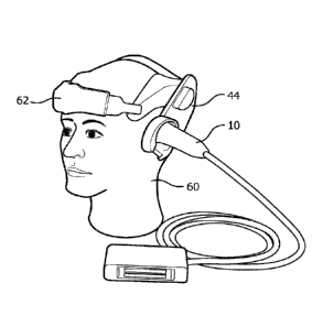
against the head with a headset. For instance, FIGURE 2a shows a headset 62
for two matrix
array probes 10 mounted on the head 60 of a mannequin. The sides of the head
of most
patients advantageously provide suitable acoustic windows for transcranial
ultrasound at the
temporal bones around and in front of the ears on either side of the head. In
order to transmit
and receive echoes through these acoustic windows the transducer arrays must
be in good
acoustic contact at these locations which may be done by holding the
transducer arrays
against the head with the headset 62. A headset may have a snap-on deformable
acoustic
standoff 44 which allows the transducer array to be manipulated by its
conformal contact
surface and aimed at the arteries within the brain while maintaining acoustic
contact against
the temporal window. The illustrated probe 10 is curved by bending the probe
handle by 90 ,
which makes the probe more stable when attached to the headset 62, as its
center of gravity is
closer to the head and headset. The acoustic coupling objective is facilitated
by integrating a
mating spherical surface into the probe handle, which allows the probe to
pivot in the headset
62 until it is strongly and tightly coupled to the temporal window of the
patient.
FIGURE 2 illustrates the volumetric image fields 102, 104 scanned by matrix
array transducers 10a and 10b when acoustically coupled to scan through the
skull 100. A
clinician can image the cranial vasculature in these volumetric image fields
and steer the
pyramidal image fields in different directions to search for blood clots
obstructing the cranial
blood flow. At each position of the image field 102, 104 the clinician can
look for
obstructions of the blood flow in the real time images on the display, or can
capture (freeze)
an image or map of the cranial vasculature. When the vascular map is acquired
and held
statically, the image can undergo enhanced processing (e.g., compounding,
signal averaging)
to improve the resolution or scale of the image, and can be manipulated on the
screen and
examined carefully at different points and from different views in a precise
search for blood
vessel occlusions. In this way the clinician can diagnose for stenoses. If the
clinician
examines a vascular map and finds no evidence of obstruction in the blood flow
paths, the
clinician can steer the image field to another region of the cranium and
examine the vascular
CA 03007514 2018-06-06
WO 2017/097853
PCT/EP2016/080127
map of another image field. The clinician can use the Doppler data of the
vascular map or the
spectral Doppler function of the ultrasound system to take flow velocity
measurements at
specific points in the cranial vasculature, then use the report generation
capabilities of the
ultrasound system to record the measurements and prepare a report of his
diagnosis.
5 If
the clinician discovers a stenosis, therapy can be offered by applying the
method of the invention VARs at the site of the stenosis in an effort to
dissolve the blood clot
with the ultrasound beam. The clinician activates the "therapy" mode of the
ultrasound
system, and a graphic 110, 112 appears in the image field 102, 104, depicting
the vector path
of a therapeutic ultrasound beam. The therapeutic ultrasound beam is
manipulated by a
10 control on the user interface 38 until the vector graphic 110 or 112 is
focused at the site of the
blood clot. In the implementations of the present disclosure described below,
the therapy
beam is automatically scanned in patterns at and around the blood clot at
which the clinician
has aimed the vector graphic. The therapeutic beam can be a tightly focused,
convergent
beam or a beam with a relatively long focal length known as a pencil beam. The
energy
produced for the therapeutic beam can be in excess of the ultrasound levels
permitted for
diagnostic ultrasound, in which case the VARs at the site of the blood clot
will be effectively
destroyed. While not willing to be bound to any particular scientific theory,
it may be
supposed that the energy of the resulting VARs ruptures will effectively act
on the blood
clot, tending to break up the clot and dissolve it in the bloodstream. However
in some
instances insonification of the VARs at diagnostic energy levels may be
sufficient to dissolve
the clot.
FIGURE 3 is a plot of the pressure level profile of the cross-section of a
typical focused ultrasound therapy beam area used for sonothrombolysis. The
lines of the plot
show focused beam diameters at various pressure levels. VARs, and particularly
microbubbles, in the ultrasound field are destroyed rapidly by relatively
modest pressures of
50-100 kPa, but will remain therapeutically active for sonothrombolysis,
typically for several
tens of milliseconds, as long as they continue to remain in the ultrasound
field. However,
when the beam is of sufficient amplitude to have a therapeutic effect,
typically a peak
pressure of 200-400 kPa, VARs in proximity to the beam will be destroyed by
the reduced
amplitude at the sides of the beam without contributing to the therapeutic
effect. Because of
this effect, several undesired results are possible when steering an
ultrasound beam to cover a
larger treatment volume around a blood clot. If the beams are steered to be
spaced too closely
together, the therapeutic effect from successive beams will be reduced. This
is illustrated by
the picture of the blood clot shown in FIGURE 4a which shows a length of an in
vitro blood
CA 03007514 2018-06-06
WO 2017/097853
PCT/EP2016/080127
11
clot 50 which has been lysed by a therapy beam pattern made of a succession of
therapy
beams transmitted from left to right along the top of the blood clot as
indicated at 52. As the
picture shows, the initial therapy beams of the pattern are effective to
deeply break up the
clot on the left side, but the depletion of microbubbles due to unwanted
microbubbles
destruction, in proximity of the initial therapy beams, has left fewer
effective microbubbles
as the scanning proceeds to the right. The result is seen to be only a shallow
depth of clot
lysis on the right side of the bracketed area. However, if the individual
beams are spaced too
far enough apart to avoid this effect, the result is an inadequate clot
exposure to the therapy
beams, resulting in clot scalloping, as shown in FIGURE 4b at 54. The system
and method of
the present disclosure are effective to prevent both of these unwanted
results, as shown in
FIGURE 4c at 56.
In accordance with the principles of the present disclosure, a number of
unique
therapy beam scan formats are described which avoid this kind of scalloping
and treatment
effect reduction due to the premature/undesired destruction of VARs during
sonothrombolysis. These scan formats consist of the sequential use of two or
more unique
scan patterns with focused ultrasound beam spacing that is typically wide
enough to limit
undesirable microbubble destruction Transmission of the therapy beams is
interleaved in
time to still yield global and uniform clot coverage, with a sufficiently long
VAR
replenishment time between each scan pattern to ensure the presence of a large
enough VAR
concentration required for effective therapy delivery. Each scan pattern has a
focused
ultrasound beam spacing that is typically wide enough to limit unwanted VAR
destruction.
Our research has indicated that the beam spacing should, for a 400 kPa peak
pressure beam,
preferably be at least as large as the half-power beam width (corresponding to
about 70% of
maximum beam pressure), ideally on the order of the 100 kPa to half-pressure
beam width,
but no larger than the 75-100 kPa (18.75% to 25%) pressure beam width (see
FIGURE 3).
For a typical focused sonothrombolysis therapy ultrasound beam at 1 MHz set to
insonify the
VARs, particularly microbubbles, at its focal zone at 400 kPa, this beam
spacing would be
approximately in the range of 2.6 mm (size of half-power beam width) to 3.6 mm
(size of
half-pressure beam width) or to 5.2 mm.
A beam scan pattern suitable for use in accordance with the present disclosure
consists of a collection of individual focused beams, transmitted in a
sequential manner to
cover the entire clot volume and surrounding tissue, thereby ensuring an
adequate treatment
margin. Typical cerebral blood clots are cylindrical in shape, with a diameter
corresponding
to the inside diameter of the occluded vessel, 2-5 mm in the case of the
middle cerebral
CA 03007514 2018-06-06
WO 2017/097853
PCT/EP2016/080127
12
artery, and up to several centimeters in length. In order to achieve thorough
insonification of
the clot and its surrounding tissue, each scan pattern preferably covers a
typical cross-
sectional area of 1-5 cm2. This means that each scan pattern is composed of
many beams,
given a desired beam spacing and target region coverage. To further minimize
beam overlap
and resulting VAR destruction from adjacent beams, the beams of each
successive scan
pattern are positioned in between those of the preceding pattern, in an
interleaved manner. A
variety of beam pattern sequences can be used, such as two beam, three beam,
four beam, or
five beam sequences. All the beam patterns in the sequence can be different or
some of the
beam patterns can be the same.
FIGURES 5a and 5b illustrate two example beam patterns transmitted in an
example beam pattern sequence. These drawings represent the beams 70 as viewed
axially in
cross-section at the blood clot location, with the outer circle demarcating
the half pressure
beam profile and the smaller circle the peak pressure beam axis. The relative
position of the
beams and the beamwidth of the beams can be tuned to reduce the effect on
interfering with
contrast agent present in adjacent beams. For example, the outer circles of
the beams in
FIGURES 5a and 5b are not overlapping, and are spaced so as to limit adjacent
beams from
rupturing VARs or microbubbles outside of the beam focus region. A variety of
beam
patterns can also be used. For example, an X-by-Y matrix of beams can be used,
and
different numbers of beams can be selected as well. In some embodiments, the
number of
beams used, e.g., can range from 5 to 50, 10 to 30, or 10 to 20. In FIGURES 5a
to 5d, each
beam pattern consists of eight individually transmitted and focused beams
arranged in the
four by three matrix, which in this example covers a cross-sectional area of
about one square
centimeter. The center-to-center beam spacing in this example is 2.6 mm. It
can be seen that
the beams of the scan patterns of FIGURES 5a to 5d are spatially interleaved,
so that one
scan pattern will fill in the spaces between the other scan pattern.
The scan patterns of FIGURES 5a to 5d are transmitted in a four-pattern
sequence, if desired with replenishment periods or time intervals between the
transmitted
beam patterns. The region of the clot is first scanned with the beams in the
pattern of
FIGURE 5a, followed by scanning with the beams of FIGURE 5b, which are offset
to the left
from the pattern of FIGURE 5a by half of the interbeam spacing (e.g., 1.3 mm).
Then the
beam pattern of FIGURE 5a is transmitted again but offset vertically from the
beam pattern
of Figure 5a by half of the interbeam spacing (e.g., 1.3 mm), followed by
scanning with the
beam pattern of FIGURE 5b, also offset vertically from the beam pattern of
Figure 5b by half
of the interbeam spacing. After each scan pattern is executed to insonify the
targeted
CA 03007514 2018-06-06
WO 2017/097853
PCT/EP2016/080127
13
therapeutic volume, there is a pause of a few seconds (typically two seconds)
to allow new
VARs to replenish the therapeutic region, after which the next scan pattern is
executed.
Acoustically, the clot target is exposed to a substantially uniform ultrasound
field after the
completion of the four successive scan patterns, as illustrated in figure 5e.
FIGURE 6 is a numerical example of another four-pass scanning sequence in
accordance with the present disclosure. In this sequence the beams "1" of the
first beam
pattern, are spaced apart horizontally along the first, third, and fifth rows
of the grid. The
second beam pattern, represented by the grid locations "2", are spaced apart
horizontally in
the second and fourth rows and are diagonally located between the beams of the
first pattern.
The beams "3" of the third pattern fill in the spaces in the first, third, and
fifth rows which
were not scanned by the beams of the first pattern and also fill in vertically
between the
beams of the second beam pattern. The beams "4" of the fourth beam pattern are
seen to fill
in vertically between the beams of the first beam pattern and horizontally
between the beams
of the second beam pattern. The result is a full insonification of the grid
area and hence the
volume traversed by the beams. FIGURE 4c is a picture of the desired uniform
clot lysis
profile resulting from clot lysis with the beam patterns of FIGURE 6.
A three-pass scanning sequence of the same grid and volume as FIGURE 6 is
illustrated in FIGURE 7. Beams "1" of the first beam pattern are transmitted
in alternating
alignment, separated by two grid locations horizontally and one grid location
vertically. The
beams "2" of the second beam pattern are similarly transmitted in a pattern
offset from the
first beam pattern, separated by two grid locations horizontally and one grid
location
vertically. The beams "3" of the third grid pattern are offset in a pattern
different from those
of the first and second beam patterns and fill in the remaining locations in
the grid, again
separated from each other by two grid locations horizontally and one grid
location vertically.
This three-pass beam pattern sequence is also seen to fully insonify the grid
area, but spacing
the beams of each pattern to avoid undesired adjacent VAR destruction so that
these VARs
can be effectively therapeutically destroyed by a subsequent beam pattern. As
with the
previous examples, a refresh time is allowed between successive patterns to
allow the inflow
of fresh VARs to the blood clot location.
FIGURE 8 shows another example of a beam pattern that can be used in the
present disclosure. A four beam scan sequence is shown such that the beams
identified as "1"
can be scanned first. Following a wait time, such as two seconds, beams
identified as "2" can
be scanned, then beams identified as "3", and beams identified as "4".
CA 03007514 2018-06-06
WO 2017/097853
PCT/EP2016/080127
14
It will be understood that each block of the block diagram illustrations, and
combinations of blocks in the block diagram illustrations, as well any portion
of the systems
and methods disclosed herein, can be implemented by computer program
instructions. These
program instructions may be provided to a processor to produce a machine, such
that the
instructions, which execute on the processor, create means for implementing
the actions
specified in the block diagram block or blocks or described for the systems
and methods
disclosed herein. The computer program instructions may be executed by a
processor to
cause a series of operational steps to be performed by the processor to
produce a computer
implemented process. The computer program instructions may also cause at least
some of the
operational steps to be performed in parallel. Moreover, some of the steps may
also be
performed across more than one processor, such as might arise in a multi-
processor computer
system. In addition, one or more processes may also be performed concurrently
with other
processes, or even in a different sequence than illustrated without departing
from the scope or
spirit of the disclosure. The computer program instructions can be stored on
any suitable
computer-readable hardware medium including, but not limited to, RAM, ROM,
EEPROM,
flash memory or other memory technology, CD-ROM, digital versatile disks (DVD)
or other
optical storage, magnetic cassettes, magnetic tape, magnetic disk storage or
other magnetic
storage devices, or any other medium which can be used to store the desired
information and
which can be accessed by a computing device.
Vascular acoustic resonators useful in the method according to the invention
include any component capable of converting acoustic pressure in a propagation-
medium into
micron-size displacements, capable of applying strain onto blood clots or
vessel walls, also
with micron-size deformation amplitude. Preferred examples of suitable VARs
include gas-
filled microvesicles, i.e. vesicles of nano- or micron-size comprising a
stabilizing envelope
.. containing a suitable gas therein. The formulation and preparation of VARs
is well known to
those skilled in the art, including, for instance, formulation and preparation
of: microbubbles
with an envelope comprising a phospholipid, as described e.g. in WO 91/15244,
US Pat.
5,686,060 (Schneider et al.) and WO 2004/069284; microballoons with an
envelope
comprising a polymer, as described e.g. in US Pat. 5,711,933; or microcapsules
with an
envelope comprising a biodegradable water insoluble lipid, as described e.g.
in US
Pat.6,333,021. Preferably, the stabilizing envelope comprises an amphiphilic
material, more
preferably a phospholipid. Preferred phospholipids include esters of glycerol
with one or
preferably two (equal or different) residues of fatty acids and with
phosphoric acid, wherein
the phosphoric acid residue is in turn bound to a hydrophilic group. Other
preferred
CA 03007514 2018-06-06
WO 2017/097853
PCT/EP2016/080127
phospholipids include phosphatidic acids, i.e. the diesters of glycerol-
phosphoric acid with
fatty acids. Particularly preferred phospholipids are fatty acids di-esters of
phosphatidylcholine, ethylphosphatidylcholine, phosphatidylglycerol,
phosphatidic acid,
phosphatidylethanolamine, phosphatidylserine, phosphatidylinositol or of
sphingomyelin.
5 Polymer-modified phospholipids, including pegylated phospholipids, can
also be
advantageously employed for forming the stabilizing envelope of microbubbles.
Any
biocompatible gas, gas precursor or mixture thereof may be employed to fill
the above
microvesicles. Fluorinated gases are preferred, in particular perfluorinated
gases. Particularly
preferred gases are SF6, C3F8, C4F10 or mixtures thereof, optionally in
admixture with air,
10 oxygen, nitrogen, carbon dioxide or mixtures thereof, as described for
instance in US
6,881,397 or US 5,556,610.
The components forming the stabilizing envelope of the VARs, optionally in
admixture with other excipients, can be stored as a dry residue in contact
with the desired
gas(es). Microvesicles are typically prepared by contacting the dry residue in
the presence of
15 the gas(es) with an aqueous carrier (e.g., saline or glucose solution)
under gentle shaking,
thus obtaining an aqueous suspension of microvesicles. The microvesicle
suspension is then
typically administered by injection, preferably intravenously.
FIGURES 9a to 9b show experimental results conducted on rats. The figures
illustrate contrast enhanced ultrasound images of micro-embolized rat hind
limb containing
vascular acoustic resonators and insonified with therapy beams in a plurality
of sequential
patterns for a treated group (b) and a control (untreated) group (a). In
animals perfusion of rat
hind limb was assessed at a baseline FIGs.9(al) and 9(b1) performing contrast
enhanced
ultrasound imaging (CEUS) using ultrasound clinical system (Sequoi512) plus
ultrasound
contrast agent (SonoVueS). The suspension of autologous microthrombi were
injected in the
femoral artery and a successful occlusion was assessed 10 min after performing
CEUS. The
successful occlusion was evidenced by the absence of the contrast enhancement
in
iultrasound images illustrated in FIGs.9(a2) and 9(b2). Thirty minutes later
no perfusion was
visible in the control group represented by FIGs.9(a3); whereas 30 minutes
after the
treatment with the ultrasound therapy beams combined wioth the VARs in the rat
hind limb
from the treated group reperfusion was evidenced as shown in FIG.9(b3). The
ultrasound
beam pattern transmitted in the plurality of sequential patterns similar to
that described in
Figure 5 comprised 12 individually transmitted and focused beams arranged in
the four by
three matrix. The center-to-center beam spacing used in these experiments was
2.6 mm and
CA 03007514 2018-06-06
WO 2017/097853
PCT/EP2016/080127
16
the maximal peak pressure was 400kPa. Reperfusion was graded using a semi-
quantitative
grading (0: no reperfusion; 1: minimal; 2: partial; 3: complete).