Note: Descriptions are shown in the official language in which they were submitted.
287240-3
AIR TEMPERATURE SENSOR
FIELD OF THE INVENTION
[0001] The present disclosure relates to an air temperature sensor.
BACKGROUND OF THE INVENTION
[0002] Turbine engines, and particularly gas or combustion turbine engines,
are rotary
engines that extract energy from a flow of combusted gases passing through the
engine
onto a multitude of rotating turbine blades. Gas turbine engines have been
used for land
and nautical locomotion and power generation, but are most commonly used for
aeronautical applications such as airplanes or helicopters. In airplanes, gas
turbine engines
are used for propulsion of the aircraft.
[0003] During operation of a turbine engine, the total air temperature
(abbreviated TAT,
and also known as stagnation temperature) can be measured by a specially
designed
temperature probe mounted on the surface of the aircraft or the interior walls
of the turbine
engine. The probe is designed to bring the air to rest relative to the
aircraft; the air
experiences an adiabatic increase in temperature as it is brought to rest and
measured, and
the total air temperature is therefore higher than the ambient air
temperature. TAT is an
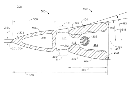
essential input for calculating static air temperature and true airspeed.
[0004] Because TAT sensors are often mounted in front of the turbine engine,
they can
be exposed to adverse conditions including high Mach numbers and icing
conditions, as
well as water and debris, which may affect the reading provided by the sensor.
BRIEF DESCRIPTION OF THE INVENTION
[0005] In one aspect, a total air temperature sensor includes a nose having an
airfoil cross
section with a leading edge and a trailing edge, a sensor housing having a
pass-through
passage and the sensor housing is spaced from and downstream of the trailing
edge to
1
CA 3007548 2018-06-07
287240-3
define a stagnation chamber between the trailing edge and the sensor housing,
a
temperature sensor located within the pass-through passage; and at least one
inlet to the
stagnation chamber where air can enter the stagnation chamber and then flow
out the pass-
through passage, wherein a chord length of the airfoil cross section is less
than 0.5 times
a total length of the total air temperature sensor.
[0006] In another aspect, a total air temperature sensor includes a nose
having an airfoil
cross section with a leading edge and a trailing edge, a sensor housing having
a pass-
through passage and the sensor housing is spaced from and downstream of the
trailing edge
to define a stagnation chamber between the trailing edge and the sensor
housing, a
temperature sensor located within the pass-through passage, and at least one
inlet to the
stagnation chamber where air can enter the stagnation chamber and then flow
out the pass-
through passage, wherein the sensor housing has an angle of attack greater
than the nose
angle of attack.
BRIEF DESCRIPTION OF THE DRAWINGS
[0007] In the drawings:
[0008] FIG. 1 is a schematic cross-sectional diagram of a gas turbine engine
for an
aircraft with a total air temperature sensor.
[0009] FIG. 2 is a perspective view of the total air temperature sensor of
FIG. 1.
[0010] FIG. 3 is a cross-sectional view of the total air temperature sensor of
FIG. 1.
[0011] FIG. 4 is a cross-sectional view of the total air temperature sensor of
FIG. 3 with
air flows illustrated.
DESCRIPTION OF EMBODIMENTS OF THE INVENTION
[0012] The described embodiments of the present disclosure are directed to a
temperature
sensor for an aircraft turbine engine. It will be understood, however, that
the disclosure is
not so limited and may have general applicability within an engine, as well as
in non-
2
CA 3007548 2018-06-07
287240-3
aircraft applications, such as other mobile applications and non-mobile
industrial,
commercial, and residential applications.
[0013] As used herein, the term "forward" or "upstream" refers to moving in a
direction
toward the engine inlet, or a component being relatively closer to the engine
inlet as
compared to another component. The term "aft" or "downstream" used in
conjunction with
"forward" or "upstream" refers to a direction toward the rear or outlet of the
engine or
being relatively closer to the engine outlet as compared to another component.
[0014] Additionally, as used herein, the terms "radial" or "radially" refer to
a dimension
extending between a center longitudinal axis of the engine and an outer engine
circumference.
[0015] All directional references (e.g., radial, axial, proximal, distal,
upper, lower,
upward, downward, left, right, lateral, front, back, top, bottom, above,
below, vertical,
horizontal, clockwise, counterclockwise, upstream, downstream, forward, aft,
etc.) are only
used for identification purposes to aid the reader's understanding of the
present disclosure,
and do not create limitations, particularly as to the position, orientation,
or use of the
disclosure. Connection references (e.g., attached, coupled, connected, and
joined) are to be
construed broadly and can include intermediate members between a collection of
elements
and relative movement between elements unless otherwise indicated. As such,
connection
references do not necessarily infer that two elements are directly connected
and in fixed
relation to one another. The exemplary drawings are for purposes of
illustration only and
the dimensions, positions, order and relative sizes reflected in the drawings
attached hereto
can vary.
[0016] FIG. 1 is a schematic cross-sectional diagram of a gas turbine engine
10 for an
aircraft. The engine 10 has a generally longitudinally extending axis or
centerline 12
extending forward 14 to aft 16. The engine 10 includes, in downstream serial
flow
relationship, a fan section 18 including a fan 20, a compressor section 22
including a
booster or low pressure (LP) compressor 24 and a high pressure (HP) compressor
26, a
3
CA 3007548 2018-06-07
287240-3
combustion section 28 including a combustor 30, a turbine section 32 including
a HP
turbine 34, and a LP turbine 36, and an exhaust section 38.
[0017] The fan section 18 includes a fan casing 40 surrounding the fan 20. The
fan 20
includes a plurality of fan blades 42 disposed radially about the centerline
12. The HP
compressor 26, the combustor 30, and the HP turbine 34 form a core 44 of the
engine 10,
which generates combustion gases. The core 44 is surrounded by core casing 46,
which
can be coupled with the fan casing 40. A total air temperature (TAT) sensor
200 can be
disposed in the fan casing 40 as shown; however, this example is not meant to
be limiting
and the TAT sensor 200 may be positioned in other locations in the turbine
engine 10.
[0018] A HP shaft or spool 48 disposed coaxially about the centerline 12 of
the engine
drivingly connects the HP turbine 34 to the HP compressor 26. A LP shaft or
spool 50,
which is disposed coaxially about the centerline 12 of the engine 10 within
the larger
diameter annular HP spool 48, drivingly connects the LP turbine 36 to the LP
compressor
24 and fan 20. The spools 48, 50 are rotatable about the engine centerline and
couple to a
plurality of rotatable elements, which can collectively define a rotor 51.
[0019] The LP compressor 24 and the HP compressor 26 respectively include a
plurality
of compressor stages 52, 54, in which a set of compressor blades 56, 58 rotate
relative to a
corresponding set of static compressor vanes 60, 62 (also called a nozzle) to
compress or
pressurize the stream of fluid passing through the stage. In a single
compressor stage 52,
54, multiple compressor blades 56, 58 can be provided in a ring and can extend
radially
outwardly relative to the centerline 12, from a blade platform to a blade tip,
while the
corresponding static compressor vanes 60, 62 are positioned upstream of and
adjacent to
the rotating blades 56, 58. It is noted that the number of blades, vanes, and
compressor
stages shown in FIG. 1 were selected for illustrative purposes only, and that
other numbers
are possible.
[0020] The blades 56, 58 for a stage of the compressor can be mounted to a
disk 61,
which is mounted to the corresponding one of the HP and LP spools 48, 50, with
each stage
4
CA 3007548 2018-06-07
287240-3
having its own disk 61. The vanes 60, 62 for a stage of the compressor can be
mounted to
the core casing 46 in a circumferential arrangement.
[0021] The HP turbine 34 and the LP turbine 36 respectively include a
plurality of turbine
stages 64, 66, in which a set of turbine blades 68, 70 are rotated relative to
a corresponding
set of static turbine vanes 72, 74 (also called a nozzle) to extract energy
from the stream of
fluid passing through the stage. In a single turbine stage 64, 66, multiple
turbine blades
68, 70 can be provided in a ring and can extend radially outwardly relative to
the centerline
12 while the corresponding static turbine vanes 72, 74 are positioned upstream
of and
adjacent to the rotating blades 68, 70. It is noted that the number of blades,
vanes, and
turbine stages shown in FIG. 1 were selected for illustrative purposes only,
and that other
numbers are possible.
[0022] The blades 68, 70 for a stage of the turbine can be mounted to a disk
71, which is
mounted to the corresponding one of the HP and LP spools 48, 50, with each
stage having
a dedicated disk 71. The vanes 72, 74 for a stage of the compressor can be
mounted to the
core casing 46 in a circumferential arrangement.
[0023] Complementary to the rotor portion, the stationary portions of the
engine 10, such
as the static vanes 60, 62, 72, 74 among the compressor and turbine section
22, 32 are also
referred to individually or collectively as a stator 63. As such, the stator
63 can refer to the
combination of non-rotating elements throughout the engine 10.
[0024] In operation, the airflow exiting the fan section 18 is split such that
a portion of
the airflow is channeled into the LP compressor 24, which then supplies
pressurized air 76
to the HP compressor 26, which further pressurizes the air. The pressurized
air 76 from
the HP compressor 26 is mixed with fuel in the combustor 30 and ignited,
thereby
generating combustion gases. Some work is extracted from these gases by the HP
turbine
34, which drives the HP compressor 26. The combustion gases are discharged
into the LP
turbine 36, which extracts additional work to drive the LP compressor 24, and
the exhaust
gas is ultimately discharged from the engine 10 via the exhaust section 38.
The driving of
the LP turbine 36 drives the LP spool 50 to rotate the fan 20 and the LP
compressor 24.
CA 3007548 2018-06-07
287240-3
[0025] A portion of the pressurized airflow 76 can be drawn from the
compressor section
22 as bleed air 77. The bleed air 77 can be drawn from the pressurized airflow
76 and
provided to engine components requiring cooling. The temperature of
pressurized airflow
76 entering the combustor 30 is significantly increased. As such, cooling
provided by the
bleed air 77 is necessary for operating of such engine components in the
heightened
temperature environments.
[0026] A remaining portion of the airflow 78 bypasses the LP compressor 24 and
engine
core 44 and exits the engine assembly 10 through a stationary vane row, and
more
particularly an outlet guide vane assembly 80, comprising a plurality of
airfoil guide vanes
82, at the fan exhaust side 84. More specifically, a circumferential row of
radially
extending airfoil guide vanes 82 are utilized adjacent the fan section 18 to
exert some
directional control of the airflow 78.
[0027] Some of the air supplied by the fan 20 can bypass the engine core 44
and be used
for cooling of portions, especially hot portions, of the engine 10, and/or
used to cool or
power other aspects of the aircraft. In the context of a turbine engine, the
hot portions of
the engine are normally downstream of the combustor 30, especially the turbine
section 32,
with the HP turbine 34 being the hottest portion as it is directly downstream
of the
combustion section 28. Other sources of cooling fluid can be, but are not
limited to, fluid
discharged from the LP compressor 24 or the HP compressor 26.
[0028] In FIG. 2, the TAT sensor 200 is illustrated comprising an axial
centerline 100, a
fore edge 201, an aft edge 202, a nose 300, and a sensor housing 400 spaced
apart and
downstream from the nose 300. The TAT sensor 200 may also include a cover
plate 204
spanning the nose 300 and sensor housing 400 as shown. In addition, the nose
300 can have
an airfoil cross section 302 (shown in further detail in FIG. 3) having a
leading edge 304
and trailing edge 306 wherein the leading edge 304 can define the fore edge
201. The TAT
sensor 200 may also be mounted to a suitable housing for attachment to the
turbine engine
10.
6
CA 3007548 2018-06-07
287240-3
[0029] FIG. 3 illustrates a cross-sectional view of the TAT sensor 200. The
airfoil 302
can have a first height 310 at the leading edge 304 and a second height 312 at
the trailing
edge 306; it is contemplated that the first height 310 may be smaller than the
second height
312, and the nose height may increase continuously between the first height
310 and second
height 312. It is also contemplated that the sensor housing 400 can include a
third height
414 near the aft edge; in non-limiting examples the third height 414 may be
greater than
the second height 312, or the third height 414 may be equal to the second
height 312 or
first height 310. Other combinations in the scope of this disclosure are
contemplated for
use in the TAT sensor 200.
[0030] The nose 300 can further include a first outer surface 316, a hollow
interior 318,
and a chord length 308, and the trailing edge 306 of the airfoil 302 may be
truncated as
shown. The sensor housing 400 can further include an axial length 402, a
second outer
surface 406, sidewalls 404, and a temperature sensor 203 positioned between
the sidewalls
404.
[0031] The TAT sensor 200 can have a total length 350 between the fore edge
201 and
aft edge 202. It is contemplated in a space-reducing configuration that the
chord length 308
of the nose 300 can be approximately the same size as the axial length 402 of
the sensor
housing 400; in a non-limiting example the chord length 308 can be less than
0.5 times the
total length 350 of the TAT sensor 200.
[0032] A stagnation chamber 410 having at least one inlet 411 can be defined
in the
region between the nose 300 and sensor housing 400. In addition, a pass-
through passage
408 having a converging inlet 412 and diverging outlet 413 can be defined
between the
sidewalls 404 of the sensor housing 400, where the converging inlet 412 can
intersect the
diverging outlet 413. The stagnation chamber 410 can be fluidly coupled to the
converging
inlet 412, and the temperature sensor 203 can be positioned within the
diverging outlet 413
as shown.
[0033] In a region proximate the stagnation chamber 410, the first outer
surface 316 of
the nose 300 can form a first angle of attack 315 with respect to the
centerline 100, and the
7
CA 3007548 2018-06-07
287240-3
second outer surface 406 of the sensor housing 400 can form a second angle of
attack 415
with respect to the centerline 100. It is contemplated that the second angle
415 may be
greater than the first angle 315 as shown; in one non-limiting example, the
first angle could
be greater than or equal to 2.0 degrees while the second angle could be
greater than or equal
to 10.0 degrees.
[0034] FIG. 4 illustrates the TAT sensor 200 of FIG. 3 along with a set of
airflows 500;
while the airflows 500 are illustrated moving in the same direction as the
centerline 100,
there may also be an angle of attack between the airflows 500 and the
centerline 100. In
operation, air can move toward the leading edge 304, and at least a portion of
air can flow
through the inlet 411 into the stagnation chamber 410 where it can be reduced
in speed or
brought to rest relative to the TAT sensor 200. A portion of air can also flow
through the
pass-through passage 408 by entering the converging inlet 412 and exiting the
diverging
outlet 413, and the temperature sensor 203 can measure the total air
temperature of the air
in its vicinity.
[0035] It can be appreciated that the size of the stagnation chamber 410 can
be chosen
such that water, ice, and debris moving toward the TAT sensor 200 may flow
past the
stagnation chamber 410 while air can flow into the stagnation chamber 410 and
be
measured by the temperature sensor 203, having the benefit of protecting the
sensor 203
within the sidewalls 404. In one non-limiting example, the temperature sensor
203 was not
impinged by water or ice in airflows moving at speeds of Mach 0.4 at an angle
of attack of
degrees.
[0036] It should be further appreciated that other TAT sensors known in the
prior art can
have longer axial lengths or chord lengths; the reduced length of the TAT
sensor 200 can
bring a number of benefits, including reducing the thermal mass of the sensor
200 as well
as reducing a boundary layer heating error that can occur as air flows along
the nose outer
wall 316 before encountering the temperature sensor 203. The smaller size of
the TAT
sensor 200 can also decrease the thermal response time of the temperature
sensor 203 as
well as reducing the thermal envelope surrounding the TAT sensor 200 in
operation.
8
CA 3007548 2018-06-07
287240-3
[0037] It should be understood that application of the disclosed design is not
limited to
turbine engines with fan and booster sections, but is applicable to turbojets
and turbo
engines as well.
[0038] While there have been described herein what are considered to be
preferred and
exemplary embodiments of the present invention, other modifications of these
embodiments falling within the scope of the invention described herein shall
be apparent
to those skilled in the art.
9
CA 3007548 2018-06-07