Note: Descriptions are shown in the official language in which they were submitted.
CA 03007971 2018-06-08
- 1 -
Method for controlling a wind turbine
The present invention relates to a method for controlling a wind turbine
having adjustable
rotor blades. Moreover, the present invention relates to a corresponding wind
turbine with
such a control method.
Wind turbines, especially those as shown in figure 1, often have rotor blades
with an
adjustable blade angle. Controlling such a wind turbine regularly contains
distinguishing
between a part-load operation and a full-load operation. In the part-load
operation, the wind
turbine is regularly operated up to a rated wind speed, with the rotor blades
having a fixed
blade angle, which is also referred to here as part-load angle, in the
process.
If the wind speed has reached the rated wind speed and increases further, the
rotor blades
are successively adjusted in terms of their angle of attack, namely rotated
out of the wind in
order to avoid too high a loading of the wind turbine. This operation above
the rated wind
speed is also referred to as full-load operation and attempts are made here to
keep the
rotational speed at the rated rotational speed and keep the emitted power at
the rated power.
Neither rotational speed nor power should exceed these values, at best by
small values.
In this way, a regulation ensures that the rotational speed approximately
maintains this rated
rotational speed value. In principle, this can be also based on another value
other than the
rated rotational speed or rated power, although this is unusual.
In any case, expressed in a simplified manner, a rotational speed regulation
is carried out
here in such a way that the blades are rotated further out of the wind in the
case of an
increasing wind in order thereby to be able to keep the rotational speed at
its value. If the
wind drops off again, the blades are correspondingly rotated back into the
wind.
- 2 -
Should this regulation fail for any reason such that the blades are not
rotated out of the
wind in the case of increasing wind, the rotational speed may rise to an
undesirably high
value. An emergency shut down, in which the wind turbine shuts down if a
corresponding
overspeed value is exceeded, is provided in order to protect the wind turbine
from such
overspeed. Then, the rotor blades are rotated with an emergency adjustment in
a
feathered position.
The disadvantage here is that this overspeed limit often lies only slightly
above the rated
rotational speed for safety reasons and what may therefore occur is that the
regulation
cannot rotate the rotor blades out of the wind quickly enough, and so this
emergency shut
down responds even though no emergency is present as the rotational speed
regulation,
in principle, works properly but could not respond quickly enough in this
particular case.
Here, there is no danger to the wind turbine because briefly exceeding this
overspeed
limit is uncritical. Only a pronounced and/or long-duration instance of
exceeding said
overspeed limit becomes problematic.
The German Patent and Trade Mark Office has searched the following prior art
in the
priority application relating to the present application: US 2009/0047116 Al,
EP 1 299
779 Bl, EP 2 583 125 B1, EP 3 029 318 A1 and WO 2008/086608 A1.
The present invention is therefore based on the object of addressing this
problem. In
particular, the intention is to provide a solution that prevents the overspeed
limit from
being exceeded even though no fault is present. At least, an alternative
solution to what is
already known should be proposed.
According to one aspect of the invention, a method as disclosed herein is
proposed.
Accordingly, a method for controlling a wind turbine having rotor blades with
an
adjustable blade angle is presumed. For wind speeds up to a rated wind speed,
the wind
turbine is operated in a part-load operation in a manner known per se. The
wind turbine is
operated in a full-load operation for wind speeds above the rated wind speed,
with the
blade angle being increased in full-load operation with increasing wind speed,
namely
adjusted in the direction of the feathered position.
Now, a limit angle is set as a minimal value of the blade angle and the wind
turbine is
controlled in such a way that the limit angle is undershot by at most a
predetermined
CA 3007971 2019-09-13
CA 03007971 2018-06-08
- 3 -
difference angle. This predetermined difference angle can also have a value of
zero,
depending on how the limit angle is set. Preferably, the limit angle and/or
the difference angle
are time-varying variables.
The invention is based on the discovery that unwanted overshooting of an
overspeed limit
value, which leads to the wind turbine being shut down, only occurs in very
specific
situations. One such special situation is where a gusty wind is present, said
wind also having
short periods of very weak wind in addition to gusts. Expressed in a
simplified manner, a
temporary lull or a gust trough may be present between two gusts in the case
of gusty winds.
For the rotational speed feedback control, this would mean that the blades are
adjusted into
to the wind in such a gust trough, when a very low wind speed is present.
Then, there may be a
strong gust which accelerates the rotor following this gust trough, with it
not being possible to
rotate the rotor blades out of the wind quickly enough because they were
rotated very
strongly into the wind on account of the gust trough, i.e., the temporary very
low wind speed.
Before the rotor blades can be rotated back from this position, the rotational
speed may have
already exceeded said overspeed limit value, having as a consequence that an
unwanted
emergency shut down is introduced.
It was also recognized that the blade angle adjustment at the start of the
full-load operation,
i.e., starting from the part-load angle, initially has little effect. Thus, at
the outset, when the
wind speed is only slightly higher than the rated wind speed, the blade angle
nevertheless
needs to be adjusted by quite a number of angle degrees so that a noticeable
effect sets in,
i.e., so that the rotational speed can be kept approximately at the rated
rotational speed. As a
result, a problem arising, especially at the outset, is that the blade angle
is greatly modified
even though the wind speed has not changed a lot. Thus, much adjustment power
is
necessary in this case and implementing the adjustment may take a
comparatively long time.
In order to avoid this, the limit angle is set as a minimum value of the blade
angle. If the
above-described gust trough now occurs, it is possible to initially reduce the
rotor blade
angle, namely rotate the latter into the wind, but only until the limit angle
has been undershot
by the predetermined difference angle. A further reduction in the blade angle
is prevented.
This prevents the blade angle from moving too far from a value that may need
to be
readopted shortly in such a gusty wind situation.
CA 03007971 2018-06-08
- 4 -
Expressed differently, the blade angle is initially in the correct position in
a gust. If the lull or
the gust trough now occurs, the angle is nevertheless not rotated very far
away from this
position, which was still adopted during the gust. Once the gust trough has
ended and a
strong gust occurs again, the blade angle need only be rotated back by a small
value to the
angle that is suitable for this now reoccurring gust.
Consequently, by setting the limit angle, a simple pragmatic solution is
created, said solution
otherwise leaving the present rotational speed feedback control, which adjusts
the blade
angle, unchanged. Only such a limit angle, which should be observed as an
additional
condition, is specified. It is possible to temporarily set the limit angle
and/or the difference
angle.
An embodiment proposes that setting of the limit angle and in addition or
alternatively
controlling the wind turbine in such a way that the limit angle is undershot
only by a
predetermined difference angle is only effectuated if at least one
predetermined gust
frequency and/or a gustiness of the wind has been set. Additionally or
alternatively, a check
can be carried out as to whether a peak rotational speed, which lies above the
rated
rotational speed by more than a predetermined tolerance value, is captured at
least once
within a predetermined period of time. During running operation, the
rotational speed cannot
be kept exactly at a setpoint value and small variations of the rotational
speed about the
setpoint value thereof, the rated rotational speed during full-load operation,
arise. The higher
rotational speeds that occur briefly in this case form these peak rotational
speeds and provide
an indication about the gustiness of the wind. An example of such a peak
rotational speed is
shown schematically in figure 2 after the time Ti. Monitoring the peak
rotational speeds is
consequently a simple way of estimating the gustiness of the wind. This is
because it was
recognized that the rated rotational speed being exceeded is an indicator for
the gustiness of
the wind.
Thus, the limit angle is not set and there is no corresponding control of the
wind turbine in
wind situations that do not have great gustiness of the wind.
Here, a gust is defined as set forth below:
CA 03007971 2018-06-08
- 5 -
A gust occurs if the measured 1-minute mean value of the wind speed is
exceeded by at
least 3 m/s within a few seconds, for example for at most 20 seconds and at
least 3 seconds
continuously. Defining a gust can also be undertaken by way of a comparison of
the current
wind speed to a 10-minute mean, with it being possible for a lower excess,
e.g. in the region
of 1.7 m/s, to be considered to be a gust. A gust can be determined
correspondingly and
hence it is also possible to count gusts and thus determine their frequency,
i.e. occurrences
per time interval.
Therefore, a gust frequency is a measure that specifies how often a gust
occurs in a
predetermined time interval. A gustiness specifies the size of the portion of
gusts in the
prevalent wind.
As a result, the rotational feedback control remains uninfluenced by this
solution according to
the invention during the majority of its use, i.e., whenever the gustiness of
the wind is not too
great. Such a limit angle is set or the corresponding control is implemented
only once
gustiness has been determined. In this respect, two options can be considered
in respect of
activating this proposed solution only in the case of gustiness in the wind.
The first option
consists of only even setting a limit angle in that case. Thus, a limit angle
that never comes to
bear, for example because it has a high negative value, could be set
previously as a limit
angle. Additionally, or alternatively, the control can be easily activated or
deactivated again
depending on the gustiness. In this case, a limit angle could always be set to
a value that is
effective as well, with this value only coming to bear once the corresponding
feedback control
is activated. Alternatively, the difference angle could also assume such a
great value that the
limit angle is never undershot by such a difference angle. Otherwise, the
difference angle can
lie in the region of 5 , for example, as will be explained in more detail
below.
Instead or additionally:
- a predetermined gustiness of the wind is reached,
- a predetermined gust frequency of the wind is reached and
CA 03007971 2018-06-08
-6-
- a peak rotational speed, which lies above the rated rotational speed by more
than a
predetermined tolerance value, is captured at least once within a
predetermined
period of time.
A further configuration proposes that the limit angle is set depending on a
captured gustiness.
Consequently, the size and/or the dynamics of such a limit angle can also be
set depending
on a captured gustiness. What is considered in this case, in particular, is to
set the limit angle
ever higher with increasingly gusty wind. Consequently, the described effect
can be set to a
value that is as high as possible in the case of a particularly strong
gustiness of the wind, i.e.,
if many gusts with a high amplitude, too, occur, which is regularly also
accompanied by
correspondingly deep gust troughs. A similar effect can be obtained by virtue
of the difference
angle being set depending on the captured gustiness. Thus, in terms of
absolute value, too,
the difference angle should be selected to be particularly small if there is
particularly strong
gustiness with high gust amplitudes and also gust troughs with very low wind
speeds.
Preferably, the predetermined difference angle will have a value that is
selected from the list
including a value range of 0 to 100, 3 to 8 and a value of 5 . Thus, the
difference angle
preferably lies in a range from 0 to 10 , especially in a range from 3 to 8
and, in particular, it
has a value of approximately 5 .
Particularly if the limit angle approximately corresponds to the last-set,
large value of the
blade angle, a value of approximately 5 causes the blade angle not to move
far away from
the last value. Thus, if the above-described lull or the above-described gust
trough occurs
and if the angle would then be rotated back very strongly, for example by 20
or 30 , without
this restriction by the limit angle, the restriction to approximately 5 in
this case would prevent
this large difference and, should a gust reoccur, said angle is not very far
away from the
angle that would have to be set in that case.
A value in the range from 3 to 8 can also be selected instead of a value of
approximately 50
.
This also still allows a good restriction to be obtained by way of such a
difference angle. A
range from 0 to 100 also comes into consideration. In this respect, 10 is
already a large
value for the difference angle, but it may possibly still be sufficient; in
any case, it is a
significantly smaller value in comparison with the deviations of 20 or 30
mentioned above in
an exemplary manner. A lower limit of 0 for the difference angle is proposed
such that at
CA 03007971 2018-06-08
- 7 -
least the limit angle would have to be reached for the restriction of the
blade angle below to
come into effect.
Having said that, the limit angle also could be modified by an arbitrary value
from a purely
computational point of view, of course, and the difference angle could be
modified by this
arbitrary value in the same way. Although this is not proposed according to
the invention, the
result would end up the same and hence, as a result, this would realize the
teaching
according to the invention. Thus, if a limit angle of 200 is set in relation
to a current instant
and a difference angle of 5 is chosen, the blade angle must not drop below 15
at this
moment.
An embodiment proposes that the limit angle is ascertained as a mean value or
a filtered
value of the last set blade angles. Expressed in slightly simplified manner,
the limit angle
approximately assumes the last blade angle value set, but changes
substantially more
sluggishly. The underlying concept in this case is that, by way of a limit
angle chosen thus
together with a difference angle that is greater than zero, the blade angle
does not deviate
from this value, corresponding approximately to its last value, more strongly
than by said
difference angle.
The sluggish change can be effectuated here by forming a mean value, for
example, by virtue
of averaging over the last 8 seconds the blade angles set during this time. If
the wind now
drops off significantly and if the controller attempts to correspondingly
strongly reduce the
blade angle, this will quickly hit the limit arising from the limit angle and
difference angle.
However, the limit angle will also follow this at least slightly reduced blade
angle slowly, and
so there is also a reduction in the limit angle, albeit very slowly. What this
can achieve is that
there cannot be a strong reduction in the blade angle, and hence in the limit
angle, too,
during the above-described gust trough, which should not persist for very
long, because the
time duration of the gust trough is too short to this end. However, should the
wind remain
permanently at a low value, the limit angle can also reduce accordingly and
the blade angle
can ultimately also assume a correspondingly low value, which is suitable for
the then
prevailing weak wind speed. This is because if the wind speed is low for a
relatively long
period of time, a sudden gust is also no longer expected and hence the
installation may also
deviate by a high value in terms of its blade angle from a blade angle that
would be
necessary for a strong gust or otherwise high wind speed.
CA 03007971 2018-06-08
- 8 -
A similarly sluggish behavior of the limit angle, based on the last set blade
angles, can be
achieved by way of appropriate filtering, in particular by way of a low-pass
filter response. A
simple and efficient option for such filtering lies in the use of a first-
order delay member. The
limit angle would then be the output of such a first-order delay member which
has as an input
the current blade angle.
Preferably, different options for determining the limit angle are proposed,
specifically forming
a mean value of the last set blade angles over a period of time with a length
of 5 to 20
seconds, preferably over a period of time with a length of 6 to 15 seconds, in
particular over a
period of time with a length of approximately 8 seconds. Appropriate time
constants also can
o be set as a result thereof, said time constants being set by the proposed
ranges or the
proposed value for the length of the averaging time periods. By choosing an
averaging length
in the range of 5 to 20 seconds, it is possible to satisfy requirements which,
firstly, obtain
sufficient sluggishness for the change in the limit angle so that the blade
angle does not drop
off too strongly too quickly and then cannot be rotated to the desired high-
value quickly
enough in the case of a returning gust. Secondly, too sluggish behavior, as a
result of which
the capability of the wind turbine is impaired by the feedback control that is
too poor, is also
avoided. Selecting the time period for averaging from the range of 6 to 15
seconds takes
these two criteria into account even more. Choosing a period of time of
approximately 8
seconds can be seen to be a good value, which considers both criteria well.
Likewise, provision can be made of low-pass filtering, which chooses time
constants in the
range of 5 to 20 seconds, preferably in the range of 6 to 15 seconds and, in
particular, a time
constant of approximately 8 seconds, particularly if use is made of a first-
order low-pass filter.
The advantageous effect emerges from the same explanations as provided above
in relation
to the choice of the averaging length in respect of forming the mean value.
The use of a first-order low-pass filter, in particular of a so-called PT1
response or VZ1
response, is advantageous because such a response is free from overshoots.
Likewise,
higher order low-pass filters can also be used in the case of a similar choice
of time
constants. The remaining parameters should preferably be selected in such a
way that the
filter does not tend to overshoot. However, a first-order low-pass filter or a
mean value
formation should usually be sufficient.
CA 03007971 2018-06-08
- 9 -
One embodiment proposes that the limit angle and moreover, or alternatively,
the difference
angle is set depending on a gust frequency. This should be understood to be a
measure
specifying how often a gust occurs within a predetermined time interval. If
this gust frequency
is approximately known, it is possible to make good estimates as to how
strongly the above-
described phenomenon of the fast return of a gust after a gust trough occurs.
If this behavior
has a weaker embodiment, i.e., if there is a less strong gust return after a
gust trough, the
difference angle can be larger. Thus, a greater or faster change of the blade
angle can be
admitted. Here too, the interaction between limit angle and difference angle
is important. By
way of example, the limit angle can be set unchanged and only the difference
angle can be
set depending on the gust frequency. On the other hand, the limit angle,
instead, could be set
depending on a gust frequency. Here, it is possible to consider, in
particular, setting a time
constant or time duration of the averaging time period when forming the mean
value for the
limit angle depending on a gust frequency. Here, the time period for forming
the mean value
or the time constant of the low-pass filter should be set to be greater with
increasing gust
frequency.
Likewise, both setting the limit angle and predetermining the difference angle
can be carried
out in a manner depending on the gust frequency, but in a manner coordinated
to one
another.
According to one embodiment, the assumption is made that a fixed part-load
angle is
provided for the blade angle during the part-load operation. The suggestion to
this end is that
the limit angle or the limit angle minus the difference angle is not smaller
than this part-load
angle. Usually, the blade angle is not set to be smaller than the part-load
angle in any case
and, in this respect, also restricting the limit angle or the limit angle
minus the difference
angle to this was identified as being expedient.
One embodiment proposes that the limit angle decreases over time and/or
decreases with a
gradient that is dependent on time, in particular decreases linearly. As a
result of this, it is
possible to achieve a similar effect to when the limit angle is set by forming
a mean value or
carrying out low-pass filtering, as described above. What this decrease over
time, which can
be predetermined by way of a gradient that depends on time, achieves is that
it is possible
initially to select a limit angle which prevents the blade angle from being
reduced too strongly
after a gust. However, if a low wind speed persists for a long time, it should
also be possible
CA 03007971 2018-06-08
-
to reduce the blade angle accordingly after a certain amount of time. This can
be achieved by
the proposed change of the limit angle over time and/or by way of a temporal
gradient.
According to the invention, a wind turbine having at least one adjustable
rotor blade,
preferably having three adjustable rotor blades, and accordingly also having a
controller for
5 adjusting this rotor blade or these rotor blades is proposed. According
to the invention, the
controller is prepared to carry out a method according to at least one of the
above-explained
embodiments. In particular, the preparation of the controller can also be
realized by virtue of
a corresponding method being programmed into a control program.
Consequently, a wind turbine is proposed, said wind turbine having efficient
protection which
lo prevents an inadvertent overspeed from occurring in the case of a great
change between
gust and lull or gust trough and another gust and causing the wind turbine to
carry out an
emergency shut down even though there is no fault in the rotational speed
feedback control.
This is because the proposed method prevents such an overspeed from occurring
despite an
operational feedback control.
The invention is explained in more detail below in an exemplary manner, with
reference being
made to the attached figures.
Figure 1 shows a wind turbine in a perspective view.
Figure 2 shows a schematic diagram that is intended to elucidate relationships
between
rotational speed, wind speed and blade angle.
Figure 1 shows a wind turbine 100 with a tower 102 and a nacelle 104. A rotor
106 with a
three rotor blades 108 and a spinner 110 are arranged on the nacelle 104.
During operation,
the wind puts the rotor 106 into a rotational movement and this drives a
generator in the
nacelle 104.
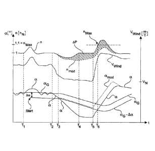
In figure 2, the wind speed Vwind, the blade angle a and the rotor rotational
speed n are
plotted over time. Although the axis label of the ordinate provides units for
the corresponding
variables, the exact values are not important for these explanations of the
basic principles.
CA 03007971 2018-06-08
- 1 1 -
In addition to the actual blade angle a, the possible curve of a limit angle
aG and a curve of
the limit angle aG minus a difference angle Ac are plotted; this is denoted as
aG-Aa in this
case. Moreover, two dotted partial curves are illustrated, namely a modified
angle amod
specifying the intended blade angle profile according to the invention, and a
rotational speed
rlmod elucidating the resultant rotational speed in this respect.
In the illustration of figure 2, the assumption is made that the wind speed
rises at the time Ti
and that a gust is present at that time. At first, as the wind speed
increases, there likewise is
an increase in the rotational speed n. The blade angle a is also increased in
order to
counteract this. It is possible to identify that the blade angle a can vary
slightly even before
the time T1 in order to keep the rotational speed n approximately constant. In
this respect,
keeping the rotational speed n constant prior to the time T1 is also quite
successful. However,
the gust occurring immediately after the time T1 leads to a noticeable
increase in the
rotational speed n.
The limit angle aG, which forms a mean value of the angle a, can also be seen
there in
addition to the curve of the angle a. Accordingly, there is a comparatively
small change in the
curve of the limit angle aG.
Moreover, the difference angle Ac is plotted for the limit angle aG. The limit
angle aG is
allowed to be undershot by no more than the difference angle Ac. Accordingly,
a limit to be
observed, which is plotted as aG-Aa, arises. Said limit starts shortly after
the time T1, and this
beginning is denoted by "Start". There was a detection at this time that a
certain gustiness of
the wind is present, and consequently the difference angle Ac was switched to
be active. In
this example, the limit angle ac is always recorded, namely as a mean value of
the angle a.
So that the difference angle Ac now finds use, the corresponding feedback
control is also
switched to be active, said feedback control monitoring whether there is
observation of the
limit angle aG being undershot by no more than the difference angle Ac.
Then, with increasing time, the gust passes and the wind speed Vwind once
again
approximately assumes the value prior to the time T1. The rotational speed n
could also be
regulated to its initial value, namely the rated rotational speed nN, in the
meantime. The blade
angle a has also been reduced correspondingly to a value approximately equal
to that before
the time T1. Variations can still be identified; these are unavoidable as the
wind also varies
CA 03007971 2018-06-08
- 12 -
slightly. These variations can hardly still be identified in the limit angle
aG, which, as stated
previously, forms a mean value of this blade angle a.
The wind speed starts to drop at the time 12. Whether this is a start of a
fundamental
reduction in the wind speed or a gust trough cannot be identified. In any
case, the wind
speed drops comparatively strongly, and so there also is reduction in the
rotational speed n
at first. The blade angle a is likewise reduced in order now to keep the
rotational speed n as
constant as possible, namely to counteract the drop in rotational speed n. On
account of the
averaging, the limit angle aG follows this curve of the blade angle a only
weakly at first.
However, the wind speed Vwind continues to drop and, at the time -13, the
blade angle a then
reaches a value that lies below the limit angle aG by the difference angle Aa.
The proposed
feedback control would now start here.
However, with the solid curve of the angle a and also the solid curve of the
rotational speed
n, figure 2 shows a curve that would set in without application of the
proposed feedback
control. Accordingly, the blade angle a would continue to drop until the
rotational speed n can
be adjusted to the original rotational speed, namely the rated rotational
speed nN at the time
14. By way of precaution, reference is made here to the fact that these
assumptions, too,
serve illustrative purposes and, by all means, it could also be the case that
the wind speed
then drops off so strongly that the wind turbine is in part-load operation and
the rotational
speed n cannot even hold the rated rotational speed nN due to a lack of wind.
However, for
.. illustrative purposes, the assumption is made that the described process
plays out completely
in full-load operation or for wind speeds that are usually settled in the full-
load operation.
Consequently, it is now possible to keep the rotational speed n at its rated
value nN according
to the full line of the blade angle a and the rotational speed n.
Now, the wind speed increases strongly again at the time T5. This may be
typical in the case
of a gusty wind speed. Accordingly, the rotational speed n also increases and
the blade angle
a likewise increases again in order to counteract this rise in the rotational
speed n.
Now, the special situation is present where the wind speed is initially
comparatively low and
the blade angle a is also comparatively small but the rotational speed n
nevertheless is at the
rated value and therefore not far away from the limit rotational speed nmAx
either. As a result
of this now quickly increasing wind, the rotational speed also increases to
such an extent that
CA 03007971 2018-06-08
- 13 -
the controller of the blade angle is no longer able to sufficiently prevent
the rotational speed
from an increase that is too strong. Consequently, the rotational speed n then
reaches the
maximum value of the rotational speed rim., at the time T6 and consequently an
emergency
shutdown would have to be implemented at the time T6; the latter would usually
also be
carried out because this is a safety aspect that cannot be precluded.
For elucidation purposes, figure 2, however, shows the further curve of the
rotational speed
n, as if this emergency shutdown were deactivated. Accordingly, it is possible
to identify that
the rotational speed n still continues to rise slightly; however, it can then
finally be adjusted
too because the blade angle a likewise increases further, it can be lowered
below the
maximum rotational speed nmax and it can finally be regulated to the value of
the rated
rotational speed nN as well.
If the method is now carried out using the proposed feedback control, the
blade angle a will
not be allowed to drop below the value of 00-Aa at the time Ta This deviating
curve is
illustrated there in dotted fashion. Consequently, this dotted line initially
extends along the
limit aG-LO. The result of this is that, initially, the rotational speed nmod
drops off more strongly
than would be the case without this feedback control. Even at the time T4,
this rotational
speed nmod Still is significantly lower than the rotational speed n without
this proposed
protective feedback control. At the time T5, too, this rotational speed nmod
Still is significantly
lower than the rotational speed n.
Then, at the time 15, i.e., at a time when there is a strong increase in the
wind, there is also a
strong increase in blade angle, namely amod. Consequently, this blade angle
amod is already
greater than the normal blade angle a. The rotational speed nmod can be
regulated
correspondingly strongly and an increase that is too high can be prevented.
Moreover, what
is advantageously additionally the case is that the rotational speed nmod is
lower than the
rotational speed n. Thus, the blade angle is greater than for the case without
this protective
feedback control and the rotational speed is lower than for the case without
protective
feedback control.
Consequently, this modified blade angle aõd leaves the limit characteristic aG-
Aa in the
upward direction at the time 15.
CA 03007971 2018-06-08
- 14 -
There is no peculiarity at the time T6 for this curve when using the
protective feedback
control. However, it is possible to identify that the modified rotational
speed now,' has not
reached the limit rotational speed MAXn and a shutdown is consequently
avoided.
Reference should also be made to the fact that the limit angle aG drops off in
a comparatively
gentle fashion even after the time T3 because, in the process, it orients
itself along the curve
of the actual angle according to the modified blade angle amod.
Finally, a hatched region has additionally been plotted in the rotational
speed characteristic,
namely the region between the rotational speed curve without protective
feedback control
and the rotational speed curve nmod with protective feedback control. This
hatched region
should elucidate the power losses that can arise due to the protective
feedback control. It
should be noted here that this only serves illustrative purposes and that, in
fact, there would
be an emergency shutdown at the time T6. Then, naturally, the hatched region
after this time
T6 would cease or, rather, it would be necessary to plot a hatched region
below the dotted
rotational speed characteristic nmod, all the way down to the time axis. Thus,
it is easily
identifiable that the supposed power losses are low and, in any case, not
negative in
comparison with the case where an emergency shutdown was able to be in fact
prevented.
Purely by way of precaution, reference is made to the fact that this hatched
region only
serves for elucidation purposes and that, naturally, the integration of the
rotational speed
over the time does not yield power, already in view of the units.
Consequently, a solution for preventing an unwanted emergency shutdown in the
case of
overspeed could be proposed in a simple manner. No hardware adaptation would
be needed
to this end. In particular, there is also no need to use stronger pitch
motors. The proposed
feedback control requires neither additional measurement variables nor
additional
manipulated variables.