Note: Descriptions are shown in the official language in which they were submitted.
CA 03008204 2018-06-12
I
Injector for filling an annular space around an anchor bolt
The invention relates to an injector for filling an annular space formed
around an anchor
bolt, a fastening arrangement with such an injector, a container with such an
injector
and a method for installing an anchor when using such an injector.
It is known to fill the annular space, which is formed around the anchor bolt
of a
mechanical anchor, particularly an expansion anchor, anchored in a hole, with
a curable
compound. The anchor can hereby be supported in a radial direction in the hole
and
also in the base plate, which can improve the load values, particularly under
dynamic
loads and/or cyclical loads in cracked concrete. According to DE 10204591 Al,
the
filling of the annular space occurs from the center of the hole, namely by a
filling
channel formed in the anchor bolt. In particular, the nozzle of an injector
device is
applied in a sealing manner to the filling channel and a compound is
introduced into the
filling channel. The introduced compound comes out through a transverse hole
in the
bolt.
WO 11116918 A2 discloses an injection washer, which has a filling orifice and
a
ventilation orifice. This injection washer is used in a method for the
subsequent
strengthening of a heavy-load anchor inserted in a hole. In the method, an
injection
device is connected to the filling orifice by means of an injection hose and a
compound
is carried from the injection device via the injection hose and via the
injection washer
into the hole.
An additional washer with a through-opening for introducing a curable compound
into
the hole is known from DE 10111470 Al. Washers with through-openings for
CA 03008204 2018-06-12
- 2 -
introducing curable compounds into the hole are also offered under the name
"Hilti
Dynamic Set". In the "Hilti Dynamic Set," an injection device is also
connected to the
through-opening and a compound is carried from the injection device via the
through-
opening into the hole.
DE 102010037755 Al describes a device for filling a slot through which an
anchor bolt
passes. According to DE 102010037755 Al, the device is not clamped under the
nut,
but can be fitted over the anchor bolt and the nut, which is meant to allow
the device to
consist of plastic.
DE 102014106662 Al describes an internal-threaded anchor and proposes, for the
purpose of sealing an anchor hole against liquid penetration, a perforated
disk-shaped
sealing flange, which is applied in a liquid-tight manner to the end of the
internal-
threaded anchor, and which has a recess on a bottom side, which can be filled
with a
sealing compound through filling openings.
Additional anchors, in which expansion elements are used in combination with
curable
compounds, are known from DE 10360156 Al, DE 102006000475 Al, DE 10216897
Al, DE 10060510 Al, WO 9857035 Al, US 5919006 A, US 5636945 A, US 5042961 A,
US 5064312 A, US 4601614 A, US 4516883 A, US 4556344 A, US 3702060A, US
3695045 A, US 3204416 A, US 3326004 A, US 2952129 A, US 3379019 A, US
2667037 A and DE 102011055878 Al.
DE 19749571 Al describes an anchor for attaching dynamically cross-loaded
objects to
an attachment base, with a chemically anchored anchor bolt, which has on its
rear
section a flange sleeve enclosing the anchor bolt, which after installing the
anchor
penetrates into the bore hole region that adjoins the borehole opening and
that has had
its diameter increased, and whose stop flange abuts the surface of the
attachment
base, wherein between the stop flange and the front end of the flange sleeve,
there is
provided an annular space that encloses the flange sleeve and can be filled
with mortar.
CA 03008204 2018-06-12
- 3
DE 102009006207 Al and US 20090180831 Al teach one to fill annular spaces
around
anchor bolts with solids.
The object of the invention is to provide an injector that is particularly
simple and quick
to operate and also inexpensive and reliable for filling an annular space
formed around
an anchor bolt, a fastening arrangement with such an injector, a container
with such an
injector and a method for installing an anchor when using such an injector.
The object is achieved according to the invention by an injector having the
features of
claim 1, a fastening arrangement with such an injector having the features of
claim 9, a
container with such an injector having the features of claim 10 and a method
for
installing an anchor when using such an injector having the features of claim
11. The
additional dependent claims indicate preferred designs.
An injector according to the invention for filling an annular space formed
around an
anchor bolt is equipped with a piston disk, which has a through-opening for
the anchor
bolt, and a quantity of a curable compound upstream from the piston disk,
wherein the
piston disk forms a piston for squeezing at least part of the quantity of the
curable
compound, particularly out of the injector, into the annular space.
A basic concept of the invention can be seen by combining the curable compound
that
is to be pressed out with a piston disk, through which the anchor bolt of the
anchor
passes. The invention recognized that in conventional fastening arrangements
using an
anchor, a washer is often provided through which the anchor bolt of the anchor
passes,
and which is pressed to the base plate to be attached to the substrate during
installation
of the anchor. The invention now proposes to arrange a quantity of a curable
compound
between this washer and the base plate, or between this washer and the
substrate
under the base plate. In this configuration, the washer acts as a piston disk,
which,
when one presses the washer against the base plate or directly against the
substrate
CA 03008204 2018-06-12
- 4
,
while installing the anchor, presses out at least a portion of the quantity of
the curable
compound in the annular space around the anchor bolt.
When using an injector according to the invention, the curable compound is
thus
pressed out automatically into the annular space around the anchor bolt in the
course of
installing the anchor. The injector according to the invention is simply
fitted on to the
anchor and the anchor nut is tightened as usual and the system is then ready.
Thus, no
additional work step and no additional tool, such as a separate injection
device, which
would have to be connected in a cumbersome manner, are required. In this way,
a
particularly simple, quick, safe, reliable and also cost-effective filling
process is
provided. Since no supply line is required according to the invention, the
quantity of
waste can also be kept particularly low. Since according to the invention one
is working
with a fluid, curable compound, which cures only after a certain time delay,
particularly
in the annular space, the requirements in terms of aligning the components are
comparatively low in contrast to systems in which solids are placed in the
annular
space.
The piston disk according to the invention forms a piston for squeezing at
least a portion
of the quantity of the curable compound out of the injector into the annular
space and
for pressing at least a portion of the quantity of the curable compound out of
the injector
into the annular space. Such an annular space often remains in the substrate
and also
in the base plate around the anchor bolt, since the anchor bolt often has a
smaller
diameter than the hole in the base plate and substrate to ensure that the
anchor bolt is
reliably inserted into the hole.
In regard to an injector according to the invention, a curable compound can be
pressed
out of the injector by an axial pressing of the piston disk against a surface,
particularly
by an axial pressing of the piston disk against the surface of the base plate,
but also
against the surface of the substrate, wherein these two surfaces enclose the
hole in
which the anchor bolt is inserted in an annular fashion. According to the
invention, there
CA 03008204 2018-06-12
- 5 -
is a piston space between the piston disk on the one hand and the substrate
and/or the
base plate on the other, said space having its volume decreased by bringing
the piston
disk closer to the substrate and/or the base plate when pressing out the
curable mass.
When operating the injector, the piston disk is brought closer axially to the
substrate
and/or to the base plate, i.e. the piston disk is moved in particular at least
almost
parallel to the through-opening in the piston disk and/or in particular at
least almost
parallel to the longitudinal axis of the anchor bolt.
To the extent that reference here is made to a radial, axial and/or
circumferential
direction, this may apply particularly to the longitudinal axis of the anchor
bolt and/or the
longitudinal axis of the injector, wherein the latter may be defined
particularly by the
through-opening in the piston disk.
The curable mass may also be referred to as a fluid, curable filler. The
compound may
involve for example a multi-component synthetic resin mortar on the basis of
polyester
or epoxy resin, which is activated by mixing the components. Particularly in
this case,
the curable compound may be present in the injector, particular in its
reservoir, in the
form of separate preliminary products, which are mixed when pressed out. The
compound is preferably an adhesive.
The anchor, to whose anchor bolt the injector according to the invention is
arranged,
can be an expansion anchor for example, preferably a bolt-type expansion
anchor. An
expansion anchor can have in particular a wedge gear, which transforms a
pulling
movement of the anchor bolt relative to the substrate into a radial movement
of an
expansion element arranged on the anchor bolt, particularly an expansion
sleeve
arranged on the anchor bolt, relative to the anchor bolt and thus anchors the
anchor to
the substrate. The anchor may also be a chemical anchor, which is anchored in
the
substrate by means of an additional curable compound, wherein this additional
curable
compound can be chemically identical to or different than the curable compound
of the
injector.
CA 03008204 2018-06-12
- 6
Particularly when mixing elements are arranged on the piston disk, this can
also be
referred to as a mixing washer. The annular space around the anchor bolt in
particular
can be an annular gap.
The piston disk can consist preferably of a metal material. For example, it
can be
manufactured in a stamping process, which may be advantageous with regard to
costs.
Depending on the design of the injector, a more or less large residual volume
of the
quantity of the curable compound will often remain in the injector, i.e. the
piston disk
generally squeezes out only a part, albeit often a large part, of the quantity
of the
curable compound into the annular space.
It is particularly preferable that the quantity of the curable compound is
arranged in a
reservoir. With this, the curable compound can be protected in a particularly
simple and
reliable manner against environmental factors, and the manufacture of the
injector can
be further simplified. For example, the reservoir can be a pouch, particularly
a foil
pouch. The reservoir can in particular have a through-opening aligning with
the through-
opening of the piston disk in order to ensure that the anchor bolt passes
through the
injector without affecting the curable compound. The reservoir can also be
omitted
particularly when the curable compound has a very high viscosity such that the
compound is sufficiently dimensionally stable due to its viscosity alone, or
if the injector
fully encloses the quantity of the curable compound.
Another preferred design of the invention consists of the injector having a
sealing
washer, where the quantity of the curable compound is arranged at least
partially, in
particular fully between, in particular axially between the piston disk and
the sealing
washer. Such a sealing washer can channel the flow of the curable compound
when
being pressed out of the injector and can thus ensure in a particularly simple
manner
that the curable compound is pressed into the annular space in a particularly
reliable
CA 03008204 2018-06-12
- 7 -
manner and especially that it is not simply squeezed away. In addition, when
using a
sealing washer, the quantity of the curable compound can be positioned in a
particularly
simple manner, since the quantity of the curable compound can be enclosed
between
the piston disk and the sealing washer. Preferably, the quantity of the
curable
compound, particularly the reservoir, can be connected to the sealing washer,
which
can be advantageous from a manufacturing perspective and can simplify the
positioning
of the quantity of the curable compound. The sealing washer can also form
mixing
channels, which can further improve the mixing of the curable compound. It may
be
provided that the sealing disk is destroyed during the process in which the
curable
compound is pressed out. For example, the sealing washer can consist of
plastic, which
may be advantageous in terms of manufacturing costs. For example, the sealing
washer may be produced in an injection-molding procedure. Preferably, the
sealing
washer may have on its side facing away from the piston disk a sealing lip for
a
particularly good sealing effect with the surface surrounding the hole.
It is particularly practical that the injector has at least one sealing
sleeve, wherein the
quantity of the curable compound is arranged at least partially within the
sealing sleeve.
Such a sealing sleeve, which can radially border a piston chamber of the
piston disk,
can counteract an undesired radial discharge of the curable compound in a
particularly
simple and reliable manner.
For practical purposes, the sealing sleeve is arranged in an axially fixed
manner at one
of the two elements, namely the piston disk or the sealing washer, and
preferably
integrally designed with it, and the respective other element, namely the
sealing
washing or piston disk, is axially displaceable in the sealing sleeve.
In this way, in a first embodiment, the piston disk can be arranged in a
displaceable,
preferably axially displaceable, manner within the sealing sleeve. In
particular, the
sealing sleeve can be attached to the sealing washer and preferably be
constructed
integrally with the sealing sleeve. The sealing sleeve consists preferably of
a plastic
CA 03008204 2018-06-12
- 8 -
material, as a result of which a particularly good sealing function can be
achieved in a
particularly simple manner.
In a second embodiment, the sealing sleeve can be attached to the piston disk,
preferably be attached at least axially, and in particular be constructed
integrally with
the piston disk. In this design, the sealing washer can be arranged in an
axially
displaceable manner within the sealing sleeve.
Two sealing sleeves may also be provided, a first one on the piston disk and a
second
one on the sealing washer. The two sealing washers may run into one another in
a
telescopic manner.
It is furthermore practical that the injector has mixing elements, which
project toward the
quantity of the curable compound, particularly toward the reservoir. Such
mixing
elements, which can be designed in a pin-type manner for example, can define
and/or
border mixing channels, and thus improve the mixing of the curable compound
when
pressed out of the injector in a particularly simple manner, so that
reliability can be
further improved. The mixing elements can be arranged on the piston disk
and/or on the
sealing washer, if the latter is present.
Preferably, the injector has recesses to accommodate at least a part of the
mixing
elements when squeezing out at least part of the quantity of the curable
compound
using the piston disk. These recesses are preferably located axially offset on
the
respective other of the two elements, namely the piston disk or the sealing
washer, to
which the mixing elements are arranged, so that the mixing elements can engage
in a
finger-like manner into the recesses when the piston disk comes closer to the
sealing
washer when pressing out the curable compound. Given good mixing action of the
curable compound, this allows for a particularly complete pressing-out of the
curable
compound.
CA 03008204 2018-06-12
- 9 -
Another preferred development of the invention is that the piston disk is
designed on its
side facing the quantity of the curable compound, i.e. preferably on its side
facing the
sealing washer, in a concave manner at least regionally, and/or that the
sealing washer
is designed on its side facing the quantity of the curable compound, i.e.
preferably on its
side facing the piston disk, in a concave manner at least regionally. Through
the
concave design of the respective disks/washers, a radial discharge of the
curable
compound can be counteracted in a particularly simple and effective manner.
The invention also relates to a fastening arrangement having an injector
according to
the invention and having an anchor with an anchor bolt, which passes through
the
through-opening of the injector. In this operationally ready configuration,
the injector and
particularly its piston disk are fitted on the anchor bolt of the anchor. In
particular, the
anchor can have an anchor nut arranged on the anchor bolt which forms an axial
bearing for the injector and thus fixes the injector in a direction axial to
the anchor bolt.
When tightening this anchor nut, the injector is pressed to the base plate or
the
substrate and the curable compound is hereby mixed and simultaneously pressed
into
the annular space. However, the anchor nut can contact the piston directly or
also
indirectly.
The invention also relates to a container containing an injector according to
the
invention and an anchor. A container can in a customary manner refer
particularly to the
whole, which comprises the packaging and the packaged goods.
The invention further relates to a method for installing an anchor with an
anchor bolt,
wherein in the method, the anchor bolt of the anchor is arranged in a hole and
by
means of an injector according to the invention, a curable compound,
particularly out of
the injector, is inserted in an annular space surrounding the anchor bolt in
the hole.
Accordingly, the injector is utilized as intended.
CA 03008204 2018-06-12
1 0 -
It is particularly preferred that the piston disk of the injector is pressed,
by tightening an
anchor nut arranged on the anchor bolt, against a surface, particularly a
surface of the
substrate, in which the annular space is formed at least regionally, or
particularly on a
surface of a base plate, in which the annular space is formed at least
regionally, and the
curable compound is hereby squeezed by the piston disk and introduced into the
annular space.
The injector according to the invention can also be used as a setting control
of the
anchor. For example, the sealing sleeve arranged on the sealing washer can be
dimensioned in such a manner that, after correct installation of the anchor
with the
injector, it protrudes axially on the exterior side of the injector beyond the
piston disk. If
the interior side of the sealing sleeve is color-coded, for example in green,
the user is
given visual confirmation that the system was correctly installed.
On a regular basis, the injector according to the invention will be positioned
between the
base plate and the anchor nut; however, the injector could basically also be
arranged
between the substrate and the base plate.
Features that are explained in connection with the injector according to the
invention
may also be used with the fastening arrangement according to the invention,
the
container according to the invention and/or the method according to the
invention, and
reciprocally features exemplified in connection with the fastening arrangement
according to the invention, the container according to the invention and/or
the method
according to the invention can also be used on the injector according to the
invention.
The invention is explained in greater detail below using preferred
embodiments, which
are depicted schematically in the attached drawings, wherein individual
features of the
embodiments depicted below can essentially be designed within the scope of the
invention either individually or in any combination. The drawings depict
schematically:
CA 03008204 2018-06-12
- 1 1 -
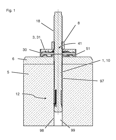
Fig. 1: A longitudinal sectional view of a fastening arrangement according to
the
invention with an injector according to the invention and an anchor, wherein
the
anchor bolt of the anchor is arranged in a hole, which extends through a base
plate into a substrate;
Fig. 2: A view from below of the piston disk of the injector from Fig. 1;
Fig. 3: A magnified view of the injector from Fig. 1 in a longitudinal
sectional view, i.e.
according to section A-A of Fig. 2;
Fig. 4: A view from below of the piston disk of the injector according to a
second
embodiment;
Fig. 5: The injector of the second embodiment in a longitudinal sectional
view, i.e.
according to section A-A of Fig. 4;
Fig. 6: A transparent view from above of an injector according to a third
embodiment;
Fig. 7: The injector of the third embodiment in a longitudinal sectional view,
i.e.
according to section A-A of Fig. 6;
Fig. 8: The piston disk of the injector of the third embodiment from below;
Fig. 9: The piston disk of the injector of the third embodiment in a
longitudinal sectional
view, i.e. according to section A-A of Fig. 8;
Fig. 10: The sealing washer of the injector of the third embodiment from
above;
Fig. 11: The sealing washer of the injector of the third embodiment in a
longitudinal
sectional view, i.e. according to section A-A of Fig. 10;
Fig. 12: A view from above of an injector according to a fourth embodiment;
CA 03008204 2018-06-12
- 12 -
Fig. 13: The injector of the fourth embodiment in a longitudinal sectional
view, i.e.
according to section A-A of Fig. 12;
Fig. 14: The piston disk of the injector of the fourth embodiment from below;
Fig. 15: The piston disk of the injector of the fourth embodiment in a
longitudinal
sectional view, i.e. according to section A-A of Fig. 14;
Fig. 16: The sealing disk of the injector of the fourth embodiment from above;
Fig. 17: The sealing disk of the injector of the fourth embodiment in a
longitudinal
sectional view, i.e. according to section A-A of Fig. 16; and
Fig. 18: A view corresponding to Fig. 1 with additional arrows to explain the
method
according to the invention.
Elements essentially acting the same are labeled with the same reference signs
in the
various embodiments.
A first embodiment of a fastening arrangement is shown in Figs. 1 to 3. The
fastening
arrangement has an anchor 1 with an anchor bolt 10 as well as an injector 3.
In the front region of anchor 1, anchor 1 has an anchoring zone 12, in which
anchor bolt
can be anchored to wall 98 of a hole 99. In Fig. 1, anchor 1 is illustratively
depicted
as a bolt-type expansion anchor. As such, anchor 1 has in anchoring zone 12 an
expansion sleeve and an expansion cone formed on anchor bolt 10 for radially
pressing
the expansion sleeve against wall 98 of hole 99, given a tension load in
anchor bolt 10.
However, the design of anchor 1 as a bolt-type expansion anchor should be
regarded
as merely illustrative, and anchor 1 can also have anchoring zones 12 that act
in other
ways. Preferably, anchoring zone 12 is a mechanical anchoring zone, in other
words an
anchoring zone which effects at least primarily a form-locking or friction-
locking
CA 03008204 2018-06-12
-13-
anchoring. Basically however, anchoring zone 12 could also be a chemical
anchoring
zone, in other words an anchoring zone which effects an at least primarily
material-
bonded anchoring.
In the rear region of anchor 1, anchor bolt 10 is equipped with an exterior
thread 18.
Screwed on to the exterior thread is an anchor nut 8 with an interior thread
corresponding to exterior thread 18.
The fastening arrangement also has an injector 3 explained in detail below,
wherein
anchor bolt 10 of anchor 1 passes through injector 3.
Fig. 1 depicts the fastening arrangement when installing anchor 1.
Accordingly, the front
end of anchor bolt 10 of anchor 1 is guided into a hole 99 in a base plate 6
and a
substrate 5, for example a concrete substrate, adjoining base plate 6.
Injector 3
surrounding anchor bolt 10 is located between anchor nut 8 and base plate 6
abutting
substrate 5, and thus also between anchor nut 8 and substrate 5. In hole 99,
an annular
space 97 is formed around anchor bolt 10 which extends from base plate 6 into
substrate 5.
Injector 3 of the embodiment of Figs. 1 to 3 has a metallic piston disk 31
with a through-
opening 41, through which anchor bolt 10 passes. Upstream from piston disk 31
is a
reservoir 33, for example a foil pouch, which contains a quantity 30 of a
curable
compound. Reservoir 33 is designed in a ring-shaped manner and surrounds
anchor
bolt 10. Upstream from reservoir 33 is a sealing washer 51, which also has a
through-
opening 61, through which anchor bolt 10 passes. Reservoir 33 is thus located
between
piston disk 31 and sealing washer 51, wherein piston disk 31 of anchor nut 8
and
sealing washer 51 faces substrate 5 and base plate 6. Sealing washer 51 has on
its
exterior side facing away from piston disk 31, i.e. on its exterior side
facing away from
quantity 30 of the curable compound, a sealing lip 55.
CA 03008204 2018-06-12
-14-
In Fig. 18, the operating mode of injector 3 of the embodiment of Figs. 1 to 3
is indicated
in a method according to the invention by means of arrows. As Fig. 18 shows,
anchor
nut 8 is tightened using exterior thread 18 of anchor bolt 10. Since anchor
bolt 10
anchors itself at its anchoring zone 12 in substrate 5, anchor nut 8 hereby
comes closer
to substrate 5. Since anchor nut 8 is cross-sectionally larger than through-
opening 41 in
piston disk 31, piston disk 31 is hereby carried along by anchor nut 8.
Consequently,
injector 3 is pressed together between anchor nut 8 on the one hand and
substrate 5
and possibly base plate 6, which form a counter-bearing for injector 3, on the
other, and
piston disk 31 is pressed against sealing washer 51. Reservoir 33, containing
quantity
30 of the curable compound, is hereby pressed out, and the curable compound
goes
out of injector 3 into annular space 97 around anchor bolt 10, where the
compound
ultimately cures, i.e. becomes rigid. In other words, the curable compound
between
piston disk 31 acting as a piston and base plate 6 is squeezed out of injector
3 into
annular space 97 around anchor bolt 10.
As particularly Figs. 2 and 3 show, piston disk 31 of injector 3 of the
embodiment of
Figs. 1 to 3 has mixing elements 37 and 37', which project toward quantity 30
of the
curable compound, particularly toward reservoir 33, from piston disk 31.
Mixing
elements 37 are pin-shaped and mixing elements 37' are crescent-shaped. Mixing
elements 37 and 37' together form a complex geometry, which ensures good
mixing of
the curable compound both in the pure translational motion of piston disk 31
and sealing
washer 51 toward each other as well as in a purely relative rotation of piston
disk 31
and sealing disk 51 toward each other without a translational motion.
Through-opening 41, provided for passing through anchor bolt 10, in piston
disk 31 can
be designed in a circular manner, for example. As shown in Fig. 3 in
particular, through-
opening 61 of sealing washer 51 conversely has a cross-sectional shape
differing from
a circular form, so that mixing lobes for the curable compound are formed at
through-
opening 61 of sealing washer 51.
CA 03008204 2018-06-12
-15-
As Figs. 1 and 3 show in particular, injector 3 of the embodiment of Figs. 1
to 3 has a
sealing sleeve 59, in which piston disk 31 is displaceably arranged, and which
seals off
injector 3, particularly its reservoir 33, in a radial direction. In the
embodiment of Figs. 1
to 3, the preferably cylindrical sealing sleeve 59 is arranged securely on
sealing washer
51 and in particular designed integrally with sealing washer 51. Basically
however,
sealing sleeve 59 and sealing washer 51 can also be separate parts. For a
particularly
good sealing effect, sealing washer 51 and/or sealing sleeve 59 in particular
can consist
of a plastic material.
Figs. 4 and 5 depict an alternative embodiment of an injector 3. Injector 3 of
Figs. 4 and
can be used in the fastening arrangement of Figs. 1 to 3 and in the method
shown in
Fig. 18 instead of the injector 3 respectively shown there.
Injector 3 of the embodiment of Figs. 4 and 5 implements a series of features
of injector
3 of the embodiment of Figs. 1 to 3 in a similar manner, so that the
aforementioned
description can be applied similarly to that extent.
However, in particular, injector 3 of the embodiment of Figs 4 and 5 differs
from injector
3 of the embodiment of Figs. 1 to 3 by the design of mixing elements 37" at
piston disk
31: In the embodiment of Figs. 4 and 5, piston disk 31 has wedge-shaped mixing
elements 37", which broaden radially outward. In the longitudinal sectional
view (Fig. 5),
piston disk 31 is constructed concavely on its side facing quantity 30 of the
curable
compound.
Furthermore, injector 3 of the embodiment of Figs. 4 and 5 differs from
injector 3 of the
embodiment of Figs. 1 to 3 by the design of through-opening 61 in sealing
washer 51:
Through-opening 61 in sealing washer 51 of the embodiment of Figs. 4 and 5 is
designed essentially circularly in its cross-section.
CA 03008204 2018-06-12
- 16
Sealing washer 51 of the embodiment of Figs. 4 and 5 once again has a sealing
sleeve
59, which prevents the curable compound from being pressed away radially and
which
instead ensures that the curable compound is primarily pressed into the center
of
injector 3 and thus into hole 99 and into annular space 97. Sealing washer 51
of the
embodiment of Figs. 4 and 5 once again also has on its exterior side facing
away from
piston disk 31, i.e. on its exterior side facing away from quantity 30 of the
curable
compound, a sealing lip 55, which abuts the surface of base plate 6 when the
injector is
in operation.
Figs. 6 to 11 show a third alternative embodiment of an injector 3. Injector 3
of Figs. 6 to
11 can be used in the fastening arrangement of Figs. 1 to 3 and in the method
shown in
Fig. 18 instead of the injector 3 respectively shown there.
Injector 3 of Figs. 6 to 11 once again has a piston disk 31 with a through-
opening 41 for
anchor bolt 10 as well as a sealing washer 51 with a through-opening 61 for
anchor bolt
10, wherein the two through-openings 41 and 61 are aligned with each other,
and
wherein between piston disk 31 and sealing washer 51, there is arranged a
reservoir 33
with a quantity 30 of a curable compound. For the sake of simplicity,
reservoir 33 is
depicted with quantity 30 of the curable compound only in Fig. 9.
Regarding the embodiment of Figs. 6 to 11, both piston disk 31 as well as
sealing
washer 51 are formed from a metal material. Once again, pin-shaped mixing
elements
57 are provided, wherein these are arranged on sealing washer 51 in the
embodiment
of Figs. 6 to 11. Piston disk 31 has recesses 38, ring-shaped here for
illustrative
purposes, for accommodating mixing elements 57. Additionally or alternatively,
recesses corresponding to the mixing elements on piston disk 31 can also be
arranged
on the piston disk 31 mixing elements and preferably on sealing washer 51.
Regarding the embodiment of Figs. 6 to 11, a sealing sleeve 39 is provided
once again,
which seals injector 3 in a radial direction. However, in contrast to the two
previously
CA 03008204 2018-06-12
-17-
described embodiments, sealing sleeve 39 according to the embodiment of Figs.
6 to 11
is arranged in an axially fixed manner to piston disk 31 and preferably
constructed
integrally with piston disk 31. Sealing disk 51 of the embodiment of Figs. 6
to 11 is
accordingly arranged in an axially displaceable manner inside sealing sleeve
39.
Regarding the embodiment of Figs. 6 to 11, both piston disk 31 as well as
sealing
washer 51 are designed concave on the interior sides respectively facing
quantity 30 of
the curable compound.
Figs. 12 to 17 show a fourth alternative embodiment of an injector 3. Injector
3 of Figs.
12 to 17 can be used in the fastening arrangement of Figs. 1 to 3 and the
method
shown in Fig. 18 instead of the injector 3 respectively shown there.
Injector 3 of Figs. 12 to 17 once again has a piston disk 31 with a through-
opening 41
for anchor bolt 10 as well as a sealing disk 51 with a through-opening 61 for
anchor bolt
10, wherein the two through-openings 41 and 61 align with each other, and
wherein
between piston disk 31 and sealing washer 51, a reservoir 33 with a quantity
30 of a
curable compound is arranged. For the sake of simplicity, reservoir 33 is
depicted with
quantity 30 of the curable compound only in Fig. 13.
Regarding the embodiment of Figs. 12 to 17, both piston disk 31 as well as
sealing
washer 51 are formed of a metal material. Once again, mixing elements 57 are
provided
on sealing washer 51, wherein these mixing elements 57 are designed having a
circular
arc shape in the embodiment of Figs. 12 to 17.
In the embodiment of Figs. 12 to 17, two sealing sleeves 39 and 59 are
provided, which
seal off injector 3 in a radial direction, namely a first sealing sleeve 39,
which is
arranged in an axially secure manner to piston disk 31 and preferably
constructed
integrally with piston disk 31, and a second sealing sleeve 59, which is
arranged in an
axially secure manner to piston disk 51 and preferably constructed integrally
with piston
CA 03008204 2018-06-12
-18-
disk 51. Sealing sleeve 39 is thereby designed with a smaller diameter than
sealing
sleeve 59, and piston disk 31 with sealing sleeve 39 is arranged in an axially
displaceable manner inside sealing sleeve 59 of sealing washer 51.