Note: Descriptions are shown in the official language in which they were submitted.
COMBINATION IMPRESSION COPING AND SCAN BODY
BACKGROUND
[00011 An impression coping can be used in a dental procedure to facilitate
the creation of a
dental impression. As an example, an impression coping can be attached to a
dental implant
installed in the jaw of a patient, and dental impression material can be
poured around the
impression coping and the implant to create an impression of the patient's
dental structures and
the impression coping. From the dental impression, a positive model of the
patient's dental
structures can be made (e.g., a stone or gypsum model).
[0002] In some procedures, a scan body can also be used to assist with
creating a custom
dental prosthesis for a patient. A scan body can be a dental component that is
attached to a
dental model and scanned. The scan body can assist in providing data to
software for digitizing a
dental model and designing a dental prosthesis. Typically, a scan body is a
separate component
that must be attached to a dental model and scanned, such that appropriate
data concerning the
patient's dental structures and/or the dental implant can be provided to the
prosthetic design
software. Further, other components might need to be attached to the dental
model during the
design of the dental prosthetic, creating a complicated set of parts.
[0003] It is therefore an object of the present disclosure to provide
improved dental
components and methods of use thereof for creating tooth prostheses.
SUMMARY
[0004] To better illustrate the system disclosed herein, a non-limiting
list of examples is
provided here:
[0005] Example 1 includes a dental impression coping comprising a coping
body having an
exterior surface configured for receiving a dental impression material,
wherein the body includes
a scanable element, and an implant interface for coupling the dental
impression coping to a
dental implant.
[0006] In Example 2, the coping of Example I can optionally further
comprise a head,
wherein the seanable element comprises a unique head geometry that is
configured for scanning
using a 3D scanner.
Page 1 or21
CA 3008248 2018-06-13
[0007] In Example 3, the coping of any one of or any combination of
Examples 1-2 can
optionally further comprise a bore extending through the coping body
[0008] In Example 4, the coping of any one of or any combination of
Examples 2-3 can
optionally include wherein the head has at least a first flat side and a first
round side.
[0009] In Example 5, the coping of Example 4 can optionally include wherein
the head has a
second flat side and a second round side, and the first and second flat sides
are substantially
parallel to each other.
[0010] In Example 6, the coping of Example 5 can optionally include wherein
the first and
second round sides of the head are interposed between the first and second
flat sides.
[0011] In Example 7, the coping of any one of or any combination of
Examples 1-6 can
optionally include wherein the implant interface comprises a tapered
transition zone and a
polygon-shaped projection.
[0012] In Example 8, a system comprising the dental impression coping of
Example 7 and a
dental implant can optionally be provided, the dental implant comprising a
body and a bore
extending into the body, wherein the bore includes a tapered section shaped to
interface with the
tapered transition zone of the implant interface of the dental impression
coping, and a polygon-
shaped recess shaped to interface with the polygon-shaped projection of the
dental impression
coping.
[0013] In Example 9, the system of Example 8 can optionally further
comprise a fixation
member with a threaded portion, wherein: the coping body comprises a bore
extending through
the coping body, and the bore of the implant comprises a threaded section, the
fixation member
being configured for insertion through the bore of the coping body and into
the bore of the
implant, such that the threaded portion of the fixation member is configured
to thread into the
threaded section of the bore of the implant to couple the dental impression
coping to the dental
implant.
[0014] In Example 10, the coping of any one of or any combination of
Examples 3-7 can
optionally include wherein the bore has a step configured to engage with a
dental component.
[0015] Example 11 includes a method of producing a dental model comprising
receiving a
dental impression with a dental impression coping disposed therein, pouring
dental modeling
material into the dental impression and around a dental implant analog coupled
to the impression
coping. allowing the dental modeling material to harden around the implant
analog and create a
Page 2 o121
CA 3008248 2018-06-13
dental model comprising at least some positive representations of a patient's
teeth, removing the
dental model from the dental impression with the dental implant analog
embedded in the dental
model, and scanning the dental model and the impression coping, while the
impression coping is
coupled to the dental implant analog, using a 3D scanner to create a digital
representation of at
least part of the dental model.
[0016] In Example 12, the method of Example 11 can optionally further
comprise removing
the dental model from the dental impression with the dental implant analog
embedded in the
dental model and the dental implant analog coupled to the impression coping,
such that the
impression coping is removed from the dental impression as the dental model is
removed from
the dental impression.
[0017] In Example 13, the method of any one of or any combination of
Examples 11-12 can
optionally include wherein the impression coping includes a coping body that
has a scanable
element.
100181 In Example 14, the method of Example 13 can optionally further
comprise scanning
the scanable element of the impression coping to create the digital
representation of at least part
of the dental model.
100191 In Example 15, the method of Example 14 can optionally include
wherein the
impression coping includes a head, and the scanable element comprises a unique
head geometry.
100201 Example 16 includes a method of producing a plurality of dental
impressions
comprising selecting a first dental impression coping from a plurality of
dental impression
copings, each of the impression copings comprising a coping body that includes
a scanable
element configured for scanning using a 3D scanner, to produce a first dental
impression using
an open-tray technique: (i) coupling the first dental impression coping to a
first dental implant
installed in the jaw of a first patient, (ii) positioning a first tray
including a first dental impression
material around the first dental impression coping so that the first dental
impression material at
least partially surrounds the first dental impression coping and creates a
negative impression of
the first dental impression coping and at least some of the first patient's
surrounding dental
structures, (iii) allowing the first dental impression material to harden and
substantially
permanently affix the dental impression coping to the dental impression
material, thereby
producing the first dental impression, and (iv) removing the first dental
impression from the
patient with the first dental impression coping embedded therein. The method
further comprises
Page 3 of 21
CA 3008248 2018-06-13
selecting a second dental impression coping from the plurality of dental
impression copings, and
to produce a second dental impression using a closed-tray technique: (i)
coupling the second
dental impression coping to a second dental implant installed in the jaw of a
second patient, (ii)
positioning a second tray including a second dental impression material around
the second dental
impression coping so that the second dental impression material at least
partially surrounds the
second dental impression coping and creates a negative impression of the
second dental
impression coping and at least some of the second patient's surrounding dental
structures, (iii)
allowing the second dental impression material to harden, thereby producing
the second dental
impression, and (iv) removing the second dental impression from the patient
with the second
dental impression coping still coupled to the second dental implant, such that
the second dental
impression includes a negative impression of the second dental impression
coping without the
second dental impression coping disposed therein.
100211 In Example 17, the method of Example 16 can optionally further
comprise detaching
the second impression coping from the second dental implant and re-inserting
the second
impression coping into the negative impression in the second dental model.
[0022] In Example 18, the method of any one of or any combination of
Examples 16-17 can
optionally include wherein each of the plurality of impression' copings
includes a head, and the
scanable element comprises a unique head geometry.
[00231 In Example 19, the method of any one of or any combination of
Examples 16-18 can
optionally include wherein each of the plurality of impression copings
comprises a bore
extending through the coping body.
[0024] In Example 20, the method of any one of or any combination of
Examples 16-19 can
optionally include wherein each of the plurality of impression copings further
comprises a head
having at least a first flat side and a first round side.
BRIEF DESCRIPTION OF THE FIGURES
[0025] The above-mentioned and other features and advantages of this
disclosure, and the
manner of attaining them, will become more apparent and the disclosure itself
will be better
understood by reference to the following description of examples taken in
conjunction with the
accompanying drawings, wherein:
Page 4 of21
CA 3008248 2018-06-13
[0026] Fig. IA is a perspective view of a combination impression coping
arid scan body,
according to an example of the disclosure, and Figs. IB-C are perspective
views of a set of
fixation members (e.g., screws) usable therewith.
[0027] Fig. 2A is a cross-sectional view of the combination impression
coping and scan body
of Fig. IA attached to an exemplary dental implant.
[0028] Fig. 2B is a cross-sectional view of the combination impression
coping and scan body
of Fig. lA attached to an exemplary dental implant analog.
[0029] Fig. 2C is a close-up view of a portion of the interface between the
combination
impression coping and scan body of Fig. IA and the dental implant analog of
Fig. 2B.
[0030] Figs. 3A-C illustrate various kits of combination impression coping
and scan bodies,
according to an example of the disclosure.
[0031] Figs. 4A-G illustrate an exemplary method of using the combination
impression
coping and scan body of Fig. 1A in an open-tray dental impression and modeling
procedure.
[0032] Figs. 5A-G illustrate an exemplary method of using the combination
impression
coping and scan body of Fig. IA in a closed-tray dental impression and
modeling procedure.
[0033] Fig. 6 is a perspective view of the combination impression coping
and scan body of
Fig. lA attached to an exemplary dental model.
100341 Corresponding reference characters indicate corresponding parts
throughout the
several views. The exemplifications set out herein illustrate examples of the
disclosure, and such
exemplifications are not to be construed as limiting the scope of the
disclosure any manner.
DETAILED DESCRIPTION
100351 In describing the examples of the disclosure illustrated and to be
described with
respect to the drawings, specific terminology will be used for the sake of
clarity. However, the
disclosure is not intended to be limited to any specific terms used herein,
and it is to be
understood that each specific term includes all technical equivalents.
100361 The present disclosure is directed at various designs for impression
copings, which
can also act as scan bodies. As such, the phrase "combination impression
coping and scan body"
is sometimes used throughout the disclosure to refer to such a dental
component. At other points
Page 5 of 21
CA 3008248 2018-06-13
of the disclosure, only the phrase impression coping is used to refer to the
applicable component
(e.g., merely for brevity's sake). The combination impression coping and scan
body can be used
to take a dental impression of a patient's dental structures and/or a dental
implant installed in the
patient. Subsequently, the same combination impression coping and scan body
can form part of
a dental model and be scanned using scanning equipment ¨ i.e., the impression
coping can act as
a scan body in the development of a custom dental prosthesis (e.g., a crown).
Further, the
combination impression coping and scan body can be versatile in that it can be
used in open-tray
dental impression/modeling techniques, or closed-tray dental
impression/modeling techniques.
As such, the combination impression coping and scan body can be considered
multi-functional.
For example, it can act as an impression coping, a scan body, and it can be
used in either open-
tray or closed-tray dental impression/modeling techniques.
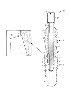
[00371 Referring to Fig. 1A, a combination impression coping and scan body
10 is shown.
Impression coping 10 can have a head 12, a body 20, and a projection 24. Head
12 can, in an
example, have a bulbous shape. Head 12 can have flat sides 16 and round sides
18, which can
define the bulbous shape. In addition, a bore 14 can extend partly or entirely
through impression
coping 10, as shown. Flat sides 16 of head 12 can extend from a corona] end 13
of impression
coping 10 to a ledge 22. In an example, each ledge 22 can be a portion of body
20 of impression
coping that extends outwards relative to flat sides 16. Round sides 18 can
connect each of flat
sides 16 of head 12, as shown in Fig. 1A. In addition, a groove 28 can be
present in head 12 of
impression coping 10 that can bifurcate or divide round sides 18 of head 12.
[0038] Still referring to Fig. IA, body 20 of impression coping 10 can be
cylindrical or part
cylindrical, although other shapes are contemplated, as shown in Figs. 3A-C
(discussed below).
Further, a projection 24 can extend apically relative to body 20, and a
tapered transition zone 21
can be disposed between projection 24 and body 20. In an example, projection
24 can have a
polygonal shape (e.g., hexagonal) so as to be able to interface with a like-
shaped section of a
dental implant or another dental component, as detailed below.
100391 As shown in Figs. 3A-C, the disclosure contemplates that a system or
kit of
impression copings 10, 10', 10" can also be provided. The size of ledges 22,
22', 22" in the kit
can change, as illustrated, as can the shape of body 20, 20', 20" of each
impression coping 10,
I 0', 10". For example, within each set of impression copings 10, 10', 10",
body 20, 20', 20" can
progressively increase in width along at least a certain cross-section of body
20, 20', 20", which
Page 6 of 21
CA 3008248 2018-06-13
can cause the size of ledges 22, 22', 22" to progressively increase. Further,
the progressive
increase of the cross-sectional width of body 20, 20', 20" can result in
certain bodies 20, 20, 20"
within each set of impression copings 10, 10', 10" having a different shape.
In an example, some
of the larger bodies 20, 20', 20" within a set of impression copings 10, 10',
10" can be part
cylindrical and part paraboloid. In an example, certain impression copings 10,
10', 10" within
each set (e.g., larger copings 10, 10', 10") can have a body 20, 20', 20" with
a coronal section
that is paraboloid in shape, and an apical section that is cylindrical in
shape. In other examples,
the coronal section and/or the apical section of body 20, 20', 20" of certain
impression copings
10, 10', 10" within each set can also progressively increase in width, as
shown. In even still
other examples, although not shown, the length of impression copings 10, 10',
10" can vary
throughout the kit to suit the particular patient at hand. Also, the size
and/or shape of the
bulbous portion of head 12, 12', 12" of impression copings 10, 10', 10" can be
the same between
each set of copings 10, 10', 10", the size and/or shape of the bulbous portion
of head 12, 12', 12"
of impression copings 10, 10', 10" can be different between 'each set of
copings 10, 10', 10", or
the size and/or shape of the bulbous portion of head 12, 12', 12" of
impression copings 10, 10',
10" can be the same or different within each set of copings 10, 10', 10".
Although the disclosure
below (and somewhat above) focuses on impression coping 10, it should be
understood that all
of the features and methods discussed with reference to impression coping 10
are equally
applicable to impression copings 10', 10". Applicant merely uses impression
coping 10 herein
for reference and convenience purposes.
[0040]
Referring back to Figs. IA-C, various fixation members 30, 40 are also shown
that
can be used with impression coping 10. Fixation members 30, 40 can be
different size screws, in
an example. Each fixation member 30, 40 can have a head 32, 42, a body 34, 44,
and a shaft 36,
46 extending from body 34, 44. Shaft 36, 46 can have a threaded section 38,
48. Further, a bore
31, 41 can extend partly or entirely through fixation member 30, 40. In an
example, bore 31, 41,
can extend partly into head 32, 42 and/or body 34, 44, as shown in Figs. 2A-C,
and can also
contain a polygonal opening 33, 43. Each polygonal opening 33, 43 can be
shaped and
configured to engage with a like-shaped portion of a driving tool, as
described more fully below.
Polygonal opening 33 can be recessed into head 32, as shown in Fig. 2A. In
addition, in an
example, fixation member 30 can be designed for connecting impression coping
10 with a dental
implant (e.g., as shown in Fig. 2A), and fixation member 40 can be designed
for connecting
Page 7 of 2 1
CA 3008248 2018-06-13
impression coping 10 with a dental implant analog (e.g., as shown in Figs. 2B-
C). Alternatively,
fixation members 30, 40 can be used interchangeably, of course.
[0041] Referring to Fig. 2A, an impression coping 10 is shown attached to a
dental implant
50. Dental implant 50 is only exemplary and a number of suitable dental
implants can be used.
As an example, the dental implant can be any dental implant disclosed in U.S.
Patent Pub. No.
2014/0272791 ("the '791 Publication"), or any other suitable dental implant.
As shown,
dental implant 50 can have a body 54, which can have external ridges or
threading in some cases.
Further, dental implant 50
can have an internal bore 56 that has a tapered section 58, a polygon-shaped
section
59, and a threaded section 57. Such features can mirror the features provided
with the dental
implants of the '791 Publication. In an example, tapered section 58 of bore 56
can be tapered by
a degree that is sufficient to establish a slight friction-fit with a portion
of impression coping 10,
or alternatively tapered section 58 can be tapered by a degree that is
sufficient to establish a slip-
fit with a portion of impression coping 10.
[0042] As shown in Fig. 2A, impression coping 10 can be attached to dental
implant 50, such
that projection 24 of impression coping 10 mates with polygon-shaped section
59 of implant 50
and tapered transition zone 21 mates with tapered section 58. In addition, an
outer ledge 26 of
impression coping 10 can engage with coronal end 52 of dental implant 50, as
shown in the
close-up view of Fig. 2A. Further, fixation member 30 can be used to attach
impression coping
to dental implant 50. In an example, threaded section 38 of fixation member 30
can be
screwed into threaded section 57 of implant 50, and an internal ledge 27
inside bore 14 of
impression coping 10 can engage with a step 35 between shaft 36 and body 34 of
fixation
member 30. As such, screwing fixation member 30 into engagement with threaded
section 57 of
implant 50 can cause impression coping 10 to move towards implant 50 and
become affixed to
implant 50. Such screwing of fixation member 30 can be performed using a
driving tool (not
shown) that engages with polygonal opening 33 of fixation member 30 and, when
rotated, can
cause rotation of fixation member 30. As shown in Fig. 2A, a portion of head
32 of fixation
member 30 can extend from impression coping 10 after impression coping 10 is
attached to
implant 50 ¨ i.e., head 32 can extend past coronal end 13 of impression coping
10, as shown.
Such positioning of head 32 can be useful in certain procedures (e.g., the
open-tray procedure of
Figs. 4A-G).
Page 8 of 21
CA 3008248 2019-07-23
[0043] Referring to Figs. 2B-C, an impression coping 10 can also be
attached to a dental
implant analog 60. The dental implant analog shown is only exemplary.
Dental implant analog 60 can have a body 64 with a coronal projection 66 and
an apical
projection 68. Further, dental implant analog 60 can have a bore 69, which can
have a threaded
section 70, a tapered section 72, and a polygon-shaped recess 74. Tapered
section 72 of bore 69
of implant analog 60 can extend from a coronal end 62 of implant analog 60
some distance
apically.
[0044] As shown in Figs. 2B-C, fixation member 40 can be used to attach
implant analog
60 to impression coping 10. In an example, threaded section 48 of fixation
member 40 can be
threaded into threaded section 70 of dental implant analog 60, and a step 45
between body 44
and shaft 46 of fixation member 40 can engage with internal ledge 27 of
impression coping 10.
Thus, fixation member 40 can be screwed into threaded section 70 of dental
implant analog 60,
and cause impression coping 10 to move towards dental implant analog 60 and
become affixed
thereto. Once attached, projection 24 of impression coping 10 can engage with
polygon-shaped
recess 74 of implant analog 60, and tapered transition zone 21 of impression
coping 10 can
engage with tapered section 72 of bore 69 of implant analog 60. Further, as
shown in Figs. 2B-C,
head 42 of fixation member 40 can be flush with or recessed below coronal end
13 of impression
coping 10.
[0045] As mentioned previously, Figs. 3A-C depict various kits of
impression copings
10, 10', 10". Each impression coping 10, 10', 10" can include generally the
same features, as
reflected by the reference numerals in Fig. 3, although the size and/or shape
of different
impression copings 10, 10', 10" can vary. Each impression coping 10, 10', 10"
can also have
features that allow impression coping 10, 10', 10" to be scanned by 3D
scanning equipment. The
scanning equipment can be, for example, a ZfxTM Evolution 3D scanner or any
other suitable 3D
scanner. In an example, the shape of head 12, 12', 12" of impression coping
10, 10', 10" (e.g., its
flat sides 16, 16', 16" and round sides 18, 18', 18") can render impression
coping 10, 10', 10"
effective for 3D scanning. As such, the unique shape of head 12, 12', 12" can
be considered a
Page 9 of 21
CA 3008248 2020-03-18
scanable element that renders impression coping 10, 10', 10" effective for 3D
scanning. In
another example, head 12, 12', 12" can simply have a unique geometry that can
be scanned using
scanning equipment (e.g., a 3D scanner). The unique geometry can be considered
a scanable
element, and it should be recognized that other scanable elements can be
incorporated with
coping 10, 10', 10", including but not limited to laser markings or some other
scanable element.
In an example, as described in more detail below, when scanned using a 3D
scanner, impression
coping 10, 10', 10" can act as a scan body and convey data to prosthetic-
modeling software about
the location and/or angular position of a dental implant, which has been
previously installed in a
patient's jaw. For instance, the data can be conveyed to CAD/CAM software used
to design
and/or fabricate dental components.
[0046] Figs. 4A-5G illustrate various dental impression and modeling
procedures, and Fig. 6
illustrates a dental model 100, 100' created using the dental impression and
modeling procedures
of Figs. 4A-5G. In Figs. 4A-G, an open-tray impression and modeling procedure
is depicted. In
Figs. 5A-G, a closed-tray impression and modeling procedure is depicted. The
use of such
procedures with combination impression coping and scan body 10 will now be
described.
100471 As previously disclosed, any combination impression coping and scan
body 10, 10,
10" disclosed herein can be used to take a dental impression using an open-
tray impression
technique. For example, as shown in Fig. 4A, first a dental implant 50 can be
installed in a
patient's jaw, and a combination impression coping and scan body 10 can then
be attached
thereto. Dental implant 50 can be dental implant 50 shown in Fig. 2A, any
dental implant
disclosed in the '791 Publication, or any other suitable dental implant.
[0048] After dental implant 50 is implanted and impression coping 10 is
attached thereto, a
dental impression can be taken, as shown in Figs. 413-E. Referring to Fig. 4B,
first a flowable
dental impression material 80 can be placed around dental implant 50 and/or
impression coping
10, as well as the patient's dental structures (e.g, teeth, soft-tissue, jaw,
etc.) During this
process, head 32 of fixation member 30 can protrude from coronal end 13 of
impression coping
10, as shown in Figs. 2A and 4B. A tray 84 can be used during or after placing
flowable dental
impression material 80 around impression coping 10 and/or implant 50, as
described above, to
allow flowable dental impression material 80 to set. As shown in Fig. 4C, tray
84 can itself
include dental impression material 80 and act to stabilize flowable dental
impression material 80
Page 10o121
CA 3008248 2018-06-13
around impression coping 10 and/or implant 50, which allows dental impression
material 80 to
harden or set and form a dental impression 81 of the patient.
[00491 As shown in Fig. 4C, one or more openings 85 can be provided in tray
84. Dental
impression material 80 can harden about impression coping 10 and bind
substantially
permanently to coping 10. Subsequently, as shown in Fig. 4D, a tool 82 can be
used to remove
fixation member 30 from dental implant 50 and decouple impression coping 10
from dental
implant 50. In an example, tool 82 can have a section with a polygon-shaped
shaft (not shown)
that can be inserted through an opening 85 in tray 84 and into engagement with
polygon-shaped
opening 33 of fixation member 30. Then, tool 82 can be rotated to decouple
fixation member 30
from implant 50 ¨ e.g., to unscrew threaded section 38 of fixation member 30
from threaded
section 57 of bore 56 of dental implant 50. As shown in Fig. 4E, tray 84 with
hardened dental
impression material 80 and impression coping 10 embedded therein can then be
removed from
the patient and implant 50, creating a negative dental impression 81 of the
patient's dental
structures (e.g., teeth, soft-tissue, jaw, etc.), which contains impression
coping 10. As illustrated
in Fig. 4E, dental impression 81 can have negative impressions 86 of the
patient's dental
structures (e.g., teeth, soft-tissue, jaw, etc.), and also contain impression
coping 10 in one such
negative impression 86.
[0050] Turning to Figs. 4F-G, a dental implant analog (e.g., implant analog
60 or any other
suitable dental implant analog) can be attached to impression coping 10, which
is embedded
within dental impression 81. In an example, a fixation member (e.g., either
fixation member 30,
40) can be used to attach the implant analog to impression coping 10. For
instance, using
implant analog 60 as an example, polygon-shaped recess 74 of bore 69 of
implant analog 60 can
be inserted over and receive projection 24 of impression coping 10, and a
fixation member (e.g.,
either fixation member 30, 40) can be inserted through bore 14 of impression
coping 10 and into
threaded section 70 of bore 69 of implant analog 60. The fixation member can
then be rotated to
affix dental implant analog 60 to impression coping 10.
[0051] Subsequently, a flowable dental modeling material (e.g., gypsum or
stone) can be
poured into dental impression 81 and around dental implant analog 60 to create
a dental model
100. In an example, the dental modeling material can flow into negative
impressions 86 of
dental impression 81 and around dental implant analog 60 so that a positive
dental model 100 of
the patient's dental structures (e.g., teeth, soft-tissue, jaw, etc.) can be
created. The dental
Page 11 of 21
CA 3008248 2018-06-13
modeling material can be allowed to set or harden with dental implant analog
60 embedded
therein. Then, the fixation member (e.g., either fixation member 30, 40) can
be decoupled from
implant analog 60 so that dental impression 81 can be removed from dental
model 100. In an
example, the fixation member can be unscrewed from threaded section 70 of bore
69 of implant
analog 60 using a tool, and then dental impression 81 can be removed from
dental model 100.
As shown in Fig. 4G, dental model 100 can be left as a positive representation
of the patient's
dental structures (e.g., teeth, soft-tissue, jaw, etc.), and implant analog
60, or another suitable
implant analog, can be embedded in dental model 100 to act as a representation
of the dental
implant that was installed in the patient. In other words, due to the
impression and dental
modeling process, the location and/or angular position of implant analog 60
within dental model
100 can be representative or substantially match the location and/or angular
position of the dental
implant that was installed in the patient. In this way, dental model 100 and
implant analog 60
can be used to create or select other suitable prosthetic components (e.g.,
abutments, prosthetic
teeth such as a crown, etc.).
[0052] In a particular example, a scan body can be attached to implant
analog 60 within
dental model 100 and the scan body can be scanned using 3D scanning equipment
to assist with
the creation of certain prosthetic components. For instance, as shown in Fig.
6, an impression
coping 10 that is the same as impression coping 10 remaining in dental
impression 81 can be
attached to implant analog 60 and used as a scan body. Or, another scan body
can be attached to
implant analog 60. Using combination impression coping and scan body 10 as an
example,
impression coping 10 can be attached to implant analog 60, as shown in Figs.
2C and 6, and then
scanned using a 3D scanner. At the same time, the remainder of dental model
100 can be
scanned to digitize the patient's surrounding dental structures (e.g., teeth,
soft-tissue, jaw, etc.)
Data from the 3D scan can then be transferred to prosthetic design software
where a digital
model of dental model 100, impression coping 10, dental implant analog 60,
and/or dental
implant 50 can be created. An example of such a digital modeling process is
disclosed in U.S.
Patent Nos. 8,185,224, 8,612,037, and 8,855,800.
Fig. 6 illustrates an impression coping 10 attached to dental model 100, which
can be scanned
as detailed above.
[0053] Using the accurate digital model obtained by way of scanning dental
model 100 and a
scan body (Fig. 6), various prosthetic components can then be designed using
prosthetic design
Page 12 of 21
CA 3008248 2019-07-23
software (e.g., CAD/CAM software). The design of custom prosthetic components
using
software is described in the '224, '037, and '800 Patents referenced above,
and any techniques
disclosed therein can be used with the present method to create custom
components. For
instance, a custom abutment can be designed, and/or a custom prosthetic tooth
(e.g., a crown). In
an alternative example, suitable pre-fabricated abutments can be attached to
dental model 100 via
implant analog 60 until an appropriate pre-fabricated abutment is located. The
appropriate pre-
fabricated abutment can then be used with the actual patient's dental implant
¨ i.e., the pre-
fabricated abutment can be installed on the patient's dentai implant, after
which a prosthetic
tooth can be attached to the abutment. As such, various combinations are
possible and it should
be appreciated that impression coping 10 can be used in an open-tray
impression procedure
similar to that described above to create a dental model, which can be used to
select and/or
design various prosthetic components (e.g., abutments, crowns, etc.) for use
with the patient's
actual dental implant.
[00541 Figs. 5A-G illustrate a closed-tray impression procedure using a
combination
impression coping and scan body 10, as disclosed herein. As such, combination
impression
coping and scan body 10 is versatile and can be used in open-tray and closed-
tray impression
techniques, as detailed below. First, as shown in Fig. 5A, a dental implant
(e.g., dental implant
50) can be inserted into the jaw of a patient, and a combination impression
coping and scan body
can then be attached thereto. Of course, the dental implant can be allowed to
affix to the
patient's jaw bone through healing and possible use of a healing abutment
after initial
implantation. In this case, the healing abutment can be removed prior to
attaching combination
impression coping and scan body 10 to the dental implant.
[0055] As shown in Figs. 5B-C, a flowable dental impression material 80'
can be applied
around impression coping 10 and/or the patient's surrounding dental structures
(e.g., teeth, soft-
tissue, jaw, etc.) Then, as shown in Fig. 5C, a suitable tray 84' with
additional dental impression
material 80' can be positioned over impression coping 10 and the patient's
surrounding dental
structures to create a dental impression 81' of the patient. While tray 84' is
positioned on the
patient, dental impression material 80' can be allowed to set or harden to
create dental impression
81'. In the closed-tray technique, as shown in Fig. 5D, impression coping 10
can be configured
to remain coupled to dental implant 50 when tray 84' and dental impression 81'
are removed
from the patient's dental structures. As an example, although not shown,
fixation member 40
Page 13 of 21
CA 3008248 2018-06-13
might be used to connect impression coping 10 to dental implant 50. As such,
fixation member
40 could be flush with or recessed below coronal end 13 of impression coping
10, similar to as
shown in Fig. 2C with respect to implant analog 60. In this way, an
appropriate negative
impression of impression coping 10 can be taken using dental impression
material 80'. In other
words, since fixation member 40 can be flush with or recessed below coronal
end 13 of
impression coping 10, when tray 84' and dental impression 81' are removed from
the patient,
impression coping 10 can remain coupled with dental implant 50 and create a
suitable negative
impression of coping 10 inside dental impression 81'. An exemplary negative
impression 88 of
impression coping 10 is shown in Fig. 5D, along with other negative
impressions of the patient's
surrounding dental structures (e.g., teeth, soft-tissue, jaw, etc.)
[0056] As shown in Figs. 5E-F, impression coping 10 can be removed from the
patient and
an appropriate implant analog (e.g., implant analog 60) can be attached to
impression coping 10.
For example, implant analog 60 can be attached to impression coping 10 in the
manner shown
and described with reference to Fig. 2C. Then, as shown in Fig. 5F, impression
coping
10/implant analog 60 structure can be manipulated and impression coping 10 can
be inserted into
negative impression 88. In an alternate example, impression coping 10 can be
inserted into
negative impression 88, and then a suitable implant analog (e.g., implant
analog 60) can be
attached to impression coping 10, instead of at the same time.
[0057] Dental impression 81' with impression coping 10 and implant analog
60 attached
thereto within negative impression 88 can then be used to fabricate a dental
model 100'
corresponding to dental impression 81'. In an example, dental impression 81'
can be sent to a
laboratory to fabricate dental model 100'. Flovvable dental modeling material
can be poured into
dental impression 81' around implant analog 60 and allowed to set or harden to
create dental
model 100' with dental implant analog 60 embedded therein. Then, as shown in
Figs. 5G and 6,
dental model 100' can be separated from dental impression 81' while leaving
impression coping
coupled to dental implant analog 60. As such, impression coping 10 can be
pulled out of
negative impression 88 of dental impression 81' once more to remain with
dental model 100 as
dental model 100' is separated from dental impression 81'. Of course,
impression coping 10
could instead first be decoupled from dental implant analog 60, dental model
100' separated from
dental impression 81', and then impression coping 10 removed from negative
impression 88 of
dental impression 81' and attached to implant analog 60 of dental model 100'
in separated steps,
Page 14 01'21
CA 3008248 2018-06-13
if preferred. The point is that the same impression coping 60 used to form
dental impression 81'
can remain with dental model 100 for subsequent use, as discussed below.
[0058] Next, impression coping 10 that is part of dental model 100' can be
used as a scan
body, as detailed previously. Thus, as an example, combination impression
coping and scan
body 10 (Fig. 6) can be scanned using a 3D scanner, along with the remainder
of dental model
100', to digitize the patient's surrounding dental structures (e.g., teeth,
soft-tissue, jaw, etc.) Data
from the 3D scan can then be transferred to prosthetic design software where a
digital model of
dental model 100', impression coping 10, dental implant analog 60, and/or
dental implant 50 can
be created.
100591 Using the accurate digital model obtained by way of scanning dental
model 100' and
combination impression coping and scan body 10 (Fig. 6), various prosthetic
components can
then be designed using prosthetic design software. For instance, a custom
abutment can be
designed, and/or a custom prosthetic tooth (e.g., a crown). In an alternative
example, suitable
pre-fabricated abutments can be attached to dental model 100' via implant
analog 60 until an
appropriate pre-fabricated abutment is located. The appropriate pre-fabricated
abutment can then
be used with the actual patient's dental implant ¨ i.e., the pre-fabricated
abutment can be
installed on the patient's dental implant, after which a prosthetic tooth can
be attached to the
abutment. As such, various combinations are possible and it should be
appreciated that
impression coping 10 can be used in a closed-tray impression procedure similar
to that described
above to create a dental model, which can be used to select and/or design
various prosthetic
components (e.g., abutments, crowns, etc.) for use with the patient's actual
dental implant.
[0060] Of course, in an alternate example, a different scan body besides
combination
impression coping and scan body 10 could be used with dental model 100' and
scanned using a
3D scanner. In this case, combination impression coping and scan body 10 could
be decoupled
and removed from implant analog 60, after which a suitable scan body could be
attached to
implant analog 60. However, since combination impression coping and scan body
10 can itself
act as a scan body, such a procedure might be suboptimal as it requires
additional steps and
might be susceptible to causing human error.
[0061] It will be readily understood to those skilled in the art that
various other changes in
the details, material, and arrangements of the parts and method stages which
have been described
and illustrated in order to explain the nature of the inventive subject matter
can be made without
Page 15 o121
CA 3008248 2018-06-13
departing from the principles and scope of the inventive subject matter as
expressed in the
subjoined claims. For example, the order of method steps or stages can be
altered from that
described above, as would be appreciated by a person of skill in the art.
Page 16 of 21
CA 3008248 2019-07-23