Note: Descriptions are shown in the official language in which they were submitted.
CA 03008340 2018-06-13
WO 2017/134141
PCT/EP2017/052213
- 1 -
"Dispensing group for an espresso coffee machine with frontal insertion
of the filter holder"
* * * * * * * * * * * * *
The present invention relates in general to the sector of machines for
the preparation of beverages. More particularly it relates to a dispensing
group provided with an engaging system for a filter holder of the frontal
type and an associated espresso coffee machine with at least one such
group.
EP 2 490 578 describes an improved filter holder for an espresso
coffee machine.
The known filter holders comprise a substantially cylindrical body
which is open at the top and bottom and provided with a (single or
double) spout. The cylindrical body is configured to receive a filter filled
with coffee powder. The filter generally has a top rim suitable for resting
on the open edge of the substantially cylindrical body. The bottom of the
filter is provided with holes such that the prepared beverage is able to
flow towards the spout.
A filter holder is configured to engage onto the bottom part of a
dispensing group. Each filter holder generally has a handle for
supporting it when the filter is filled and when the filter is
emptied/cleaned. The handle is also used when the filter holder is
engaged with the dispensing group or when it is disengaged.
Typically, a filter holder is engaged with the group by means of a
screwing movement. Typically, each filter holder has two flanges
projecting outwards from the cylindrical body. The two flanges are
situated radially opposite each other and are suitably shaped so as to
form, substantially, a portion of a thread of a screw. The bottom part of
the filter holder is provided with a circular guide suitable for receiving
the thread formed by the two flanges.
In order to engage correctly a filter holder in the associated
CA 03008340 2018-06-13
. .
a
,
'
WO 2017/134141
PCT/EP2017/052213
- 2 -
dispensing group, a bartender grips the handle of the filter holder and
moves the filter holder towards the group until it reaches the correct
engaged position. After reaching this engaged position, the bartender
rotates the filter holder in an anti-clockwise direction into the position
close to the end-of-travel position and then completes engagement by
forcing the filter holder to rotate a few more degrees so as to stably lock
the filter holder together with the group and ensure sealing of the top
edge of the filter with the sealing gasket mounted in the bottom part of
said dispensing group.
In order to disengage the filter holder, the bartender first moves the
filter-holder handle in the clockwise direction and then continues to
rotate the filter holder into the position where the two flanges are no
longer supported in the circular guide of the dispensing group and the
filter holder is free to separate completely from the dispensing group.
A bartender performs this engaging and disengaging movement
dozens or even hundreds of times during the course of a working day.
The Applicant has noticed that the engaging movement and the
associated disengaging movement are unnatural and awkward and
require a significant amount of effort.
WO 2006/082064 Al discloses a device for preparing a drink from a
capsule injection of a pressurized fluid and capsule-holder adapted
therefore.
WO 2011/095926 A2 discloses a machine for the preparation of a
beverage.
US 5,555,791 A discloses a beverage dispensing apparatus having
articulated basket holding arms for baskets having varying dimensions.
EP 0 838 185 Al discloses an espresso coffee machine.
EP 1 034 729 describes an espresso coffee machine with a coffee-
holder cup designed to receive a rigid filtering container such as a rigid
pod. The cup engages slidably with a support fork so as to move
CA 03008340 2018-06-13
WO 2017/134141
PCT/EP2017/052213
- 3 -
transversely along the fork itself until it is arranged below and, in a
position coaxial with, a piston passed through by hot water under
pressure and designed to engage frontally and in a fluid-tight manner,
under the thrust of the hot water under pressure, with an edge of the
rigid filtering container.
W02015055557 describes a device for inserting a filter holder into a
coffee dispensing group. The insertion device comprises a cup-shaped
container which houses internally a perforated filter for containing the
coffee powder and which has, extending therefrom, a handle for
manipulating said container. The cup-shaped container has two flanges
which are designed to engage with an engaging element connected to
the coffee machine and comprising slide means inside which the
flanges of the cup-shaped container engage slidably along a straight
path.
SUMMARY OF THE INVENTION
WO 2006/082064 Al discloses a device for preparing a drink from a
capsule injection of a pressurized fluid and capsule-holder adapted
therefore. The device is only configured for capsules and it is not
adapted to prepare an espresso coffee from coffee powder in a filter
hold by a filter-holder. The capsule holder only carries out a
translational movement. The supply unit comprises a main guide and
reception base intended to receive the capsule-holder in the unit - a
position in which the injector is placed with reference to the fluid supply
means of the supply unit. The supply unit thus has a second part called
the supply base which actually supports the fluid supply means. The
guide base and the supply base are mounted articulated relative to one
another so that the supply base and the guide base may adopt at least
two relative positions.
The Applicant has noted that in the solution described in
W02015055557 it is necessary to displace, by means of a toggle lever
CA 03008340 2018-06-13
WO 2017/134141
PCT/EP2017/052213
- 4 -
mechanism, a series of parts such as rods for locking the filter holder
and a movable plate with which a piston is associated. This solution is
bulky, complicated and costly and increases the time needed to prepare
an espresso coffee. Moreover an additional motor is required to
displace the movable plate towards the filter holder and bring it into a
rest position ready for extracting the filter holder with the used coffee
powder (and for inserting the filter holder with fresh coffee powder).
The object proposed by the Applicant is to provide a more efficient
and practical system for connecting a filter holder to a dispensing group
of an espresso coffee machine which overcomes, at least partly, the
drawbacks of the known solutions.
According to the Applicant, this object, together with other objects, is
achieved with a filter-holder support comprising a guide system
configured to guide the filter holder by means of a substantially
translational movement. The filter-holder support is also configured to
move the filter holder towards the group by means of a rotational
movement, preferably about a substantially horizontal axis.
According to a first aspect, the present invention relates to a
dispensing group of an espresso coffee machine, wherein said group
comprises:
a coffee boiler configured to contain pressurized hot water;
a supply duct for feeding hot water under pressure towards a puck of
coffee powder, and
a filter-holder support comprising guides forming at least one sliding
surface for slidably supporting a filter holder,
wherein said filter-holder support is rotatable between a first position
for inserting the filter holder and a second dispensing position and
wherein said dispensing group comprises a mechanical locking
device for locking said filter-holder support in said second dispensing
position.
CA 03008340 2018-06-13
. .
,
f WO 2017/1341.41 .
' PCT/EP2017/052213
- 5 -
Preferably, the coffee boiler is made at least partially of a heat
conducting material.
Preferably, the filter-holder support is made at least partially of a heat
conducting material.
Preferably, the filter-holder support is rotatably hinged to the coffee
boiler so that heat is transmitted from the coffee boiler to the filter-
holder support and to the filter-holder. Therefore, advantageously, the
content of the filter (namely the puck of coffee powder) becomes heated
even before the pressurized hot water flows towards the puck of coffee
powder. This creates lower stress to the puck of coffee because the
thermal shock on the ground coffee is reduced compared to known
systems where the filter-holder is not heated. As a result, the quality of
brewed shots is remarkably improved.
Another advantage of the above embodiment is that the heat used
for heating the filter-holder (and finally the puck of coffee) does not
require any additional heating means, such as electric resistances or
the like. This means that power consumption is not increased and there
is no additional risk of failure of electric components.
It should be said that safety for the user is guaranteed by the fact that
the filter holder typically comprises an insulated handle for user's
handling.
Preferably, the filter-holder support is rotatable about an axis
substantially parallel to, or lying in, the sliding plane of the guides.
The filter-holder support may comprise an elastic member for
retaining the filter holder in a position at the bottom of a substantially
semicircular housing of the filter-holder support.
According to one embodiment, the mechanical locking device
comprises a hook and a projecting pin engageable by said hook in at
least one stable locking position.
Preferably the hook is rotatably fixed to a fixed part of the dispensing
CA 03008340 2018-06-13
. .
WO 2017/134141 .
PCT/EP2017/052213
- 6 -
group and the projecting pin is fixed to the filter-holder support.
Preferably, the hook is rigidly attached to an actuating lever.
In embodiments a group gasket is provided for forming a seal
between an edge of the filter in the filter holder and a diffuser which
diffuses water under pressure towards said puck of coffee powder.
In embodiments a piston actuated by pressurized water between a
raised position and a lowered dispensing position is also provided.
According to another aspect, the present invention comprises a
machine for preparing and dispensing espresso coffee, comprising at
least one dispensing group of the aforementioned type.
BRIEF DESCRIPTION OF THE DRAWINGS
The present invention will become clearer from the following
description, provided by way of a non-limiting example, to be read with
reference to the accompanying drawings, in which:
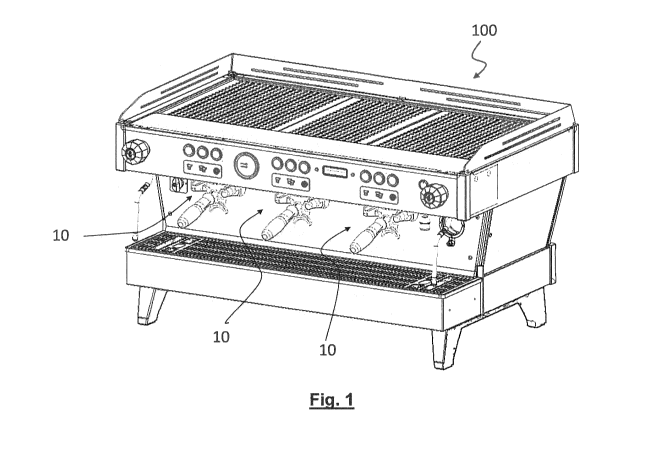
- Figure 1 shows, purely by way of example, an espresso coffee
machine with dispensing groups provided with an improved engaging
system according to the present invention;
- Figure 2.1 illustrates the step preceding the actual insertion of the
filter holder into the associated support;
- Figure 2.2 shows a cross-section of the view shown in Figure 2.1;
- Figure 2.3 shows a larger-scale view of Figure 2.1;
- Figure 2.4 shows a larger-scale view of Figure 2.2;
- Figure 3 is a cross-section which shows the filter holder inserted in
the support;
- Figure 4.1 is a cross-section which shows the filter holder inserted in
the support and the support locked;
- Figure 4.2 shows a part of Figure 4.1 on a larger scale;
- Figure 5.1 is a cross-section which shows the filter holder inserted in
the support, the support locked and the piston in the low position;
- Figure 5.2 shows a part of Figure 5.1 on a larger scale;
CA 03008340 2018-06-13
WO 2017/134141
PCT/EP2017/052213
-7-
- Figure 6 shows the position in which the filter-holder support is
completely unlocked at the end of the dispensing (or before a
dispensing operation);
- Figure 7 shows the position in which the filter-holder support is being
locked; and
- Figure 8 shows the position in which the filter-holder support is
completely locked.
DETAILED DESCRIPTION OF EMBODIMENTS
The description below, for the sake of convenience, refers in
particular to an espresso coffee machine, but the present invention is
not limited to such machines and is applicable to machines for
dispensing other beverages. For example, barley or another cereal
powder may be used instead of coffee powder. Therefore, the
expression "espresso coffee machine" must be understood as
comprising also machines for preparing other beverages. Similarly, the
expression "espresso coffee" must be understood as having a wider
meaning corresponding to the product (coffee, barley or other cereal)
used for the preparation of the beverage.
The present invention is applicable to any coffee machine, in
particular of the manually operated, automatic, semi-automatic or
completely automatic type.
Purely by way of example Figure 1 shows an espresso coffee
machine 100 provided with three dispensing groups 10 with the filter-
holder support according to an embodiment of the present invention. In
other machines a single dispensing group, two dispensing groups or
more than three dispensing groups may be present.
In the present invention only the components of the machine which
are relevant for the purposes of understanding of the present invention
will be described, while all the components of the machine which do not
have a significant influence on the present invention will not be
CA 03008340 2018-06-13
. .
' WO 2017/134141
PCT/EP2017/052213
- 8 -
described.
The various figures show a dispensing group comprising a filter-
holder support according to the present invention during the various
operating configurations and steps. They also show a system for
locking the filter-holder support.
In the present description and claims, the expression "filter-holder" is
deemed to be equivalent to "portafilter". The filter holder 1 comprises a
container body 2 which is open at the top and provided at the bottom
with a (single or double) spout which is typically curved. The filter holder
1 preferably comprises a handle or grip 4 projecting from the side
surface of the container body 2. The filter holder preferably comprises
two support flanges 5 projecting outwards from the side surface of the
container body 2. Preferably, the flanges 5 are situated on top and on
the sides in relation to the handle 4.
The container body 2 of the filter holder 1 is configured to receive
and house a filter 6 (visible for example in Figure 4.2). The filter 6 in
turn is designed to contain coffee powder or the like. The filter 6
typically is cup-shaped with a bottom provided with holes for allowing
the dispensed beverage to pass through. Preferably, the filter holder 1
is provided with a top edge configured to support the filter 6 relative to
the container body 2 of the filter holder 1.
The dispensing group 10 according to the present invention
comprises a coffee boiler 12 which is partially shown and is designed to
contain pressurized hot water for the preparation of espresso coffee or
the like. Coffee boiler 12 is partially shown in several figures and it is
shown in a complete manner in Figure 8. According to one
advantageous embodiment, the coffee boiler comprises a cylinder and
a curved neck to the dispensing group 10.
The dispensing group 10 comprises a three-way dispensing solenoid
valve 14 which draws pressurized hot water from the coffee boiler 12.
CA 03008340 2018-06-13
WO 2017/134141
PCT/EP2017/052213
- 9 -
The pressurized hot water is transported via an axial conduit 16 towards
the coffee powder (not shown) contained inside the filter 6, passing, for
example, through a diffuser 18 and a so-called "shower screen" 20
which uniformly distributes the jet of water over the puck of coffee
powder inside the filter 6.
The dispensing group 10 according to the present invention
comprises a filter-holder support 22.
Preferably, the filter-holder
support 22 comprises a substantially C-shaped or fork-shaped member.
Preferably, the filter-holder support 22 is rotatable about a pin 24.
Preferably, the filter-holder support 22 is hinged together with the boiler
12 and rotatable relative thereto between a lowered position and a
raised position. These positions will be described more fully in the
continuation of the present description. The pin 24 has an axis of
rotation which is preferably substantially horizontal.
The filter-holder support 22 comprises two substantially flat and
parallel guides 30 for supporting the filter holder 1 during a translational
movement before a dispensing operation (direction A in Figure 2.3) or
at the end of a dispensing operation (direction of the arrow B in Figure
2.3).
Preferably, the first section 30a of the guides 30 is slightly raised so
as to form a guide surface and indicate to the bartender, when he/she
pulls the filter holder 1 towards him/herself at the end of a dispensing
operation, that the filter holder 1 is losing contact with the guides 30 and
must therefore be completely supported by the bartender.
Preferably, the filter-holder support 22 comprises a substantially
semicircular housing 34 at the bottom of the C-shaped member 22.
The semicircular housing 34 is configured to embrace and receive the
portion of the container body 2 of the filter holder 1 opposite to the
handle 4 so as to distribute better the heat from the boiler group 12 onto
the container body 2 and consequently onto the filter 6.
CA 03008340 2018-06-13
WO 2017/134141
PCT/EP2017/052213
- 10 -
Preferably, the semicircular housing 34 comprises at least one elastic
tooth 32. Preferably two elastic teeth 32 are provided, each one at the
ends of the semicircular housing 34. When the filter holder 1 is forced
towards the bottom 34 of the filter-holder support 22, the elastic teeth
32 retract inside a corresponding cavity (the pushing force exerted by
the bartender acts against a slight elastic force which tends to push the
elastic teeth 32 outwards). When the filter holder 1 reaches its end-of-
travel position completely housed inside the semicircular housing 34,
the teeth 32 come out of their cavity and retain the filter holder 1 in
position. This is advantageous both during insertion of the filter holder
1 before a dispensing operation and during extraction thereof. As will
become clearer below, this measure proves to be very advantageous
when the filter-holder support 22 is in its lowered position (inclined
relative to the horizontal position). If the teeth 32 were not present, the
bartender would have to pay more attention during insertion and
extraction of the filter holder 1.
Preferably the teeth have a roughly triangular shape with chamfered
corners.
According to an embodiment of the present invention, the dispensing
group 10 comprises a group gasket 36 and a piston 38 displaceable
from a high position into a low position. In the present description, every
reference to the position of a component (for example "high" or "low") is
not limiting, but is only given for greater clarity of the invention and
refers to the drawings.
According to a preferred embodiment of the present invention, the
translational movement of the piston 38 is performed by means of the
force exerted by the hot water under pressure present inside the coffee
boiler 12. More precisely, according to an embodiment of the present
invention, the dispensing group 10 comprises an additional three-way
solenoid valve 40 configured to remove hot water under pressure from
CA 03008340 2018-06-13
WO 2017/134141
PCT/EP2017/052213
- 1 1 -
the coffee boiler 12 and introduce it into a small chamber 42 in the top
part of the dispensing group 10. In a closed position of the said
additional three-way solenoid valve 40, the water under pressure
pushes the piston 38 downwards so as to ensure a perfect sealed
closure between the filter 6 with the coffee powder and the group
gasket 36. In a released position, the solenoid valve 40 stops supplying
water under pressure and the piston 38 returns into the raised position
where there is no longer a seal between the group gasket 36 and the
filter 6.
According to preferred embodiments, the dispensing group 10
according to the present invention comprises a mechanical locking
device 50 for locking the filter-holder support 22 in the raised position
ready for dispensing.
The mechanical locking device 50 comprises a shaped hook 52, a
projecting pin 60 and an actuating lever 62. The lever 62 of the locking
device may be provided on one side of the dispensing group 10 (for
example on the right as shown in the various figures) or in a central
position. This second solution is preferred to allow easy use by right-
hand or left-hand operators.
The lever 62 is rigidly connected to the hook 52, for example by
means of a suitably shaped bracket 64. The hook 52 is rota tably pivoted
on the top part of the dispensing group 10, for example on the cover 28.
The projecting pin 60 is instead rigidly connected to the filter-holder
support 22. According to an embodiment of the invention, the
projecting pin 60 has a roughly elliptical cross-section.
The hook 52 comprises a cam with a first recess 54 for forming a
support position for the filter-holder support 22 in its lowered position.
The cam also comprises a substantially straight section 56 and a
second recess 58 for retaining the pin 60. When the pin 60 is inside the
second recess 58, the filter-holder support 22 is locked relative to the
CA 03008340 2018-06-13
WO 2017/134141
PCT/EP2017/052213
- 12 -
rest of the dispensing unit 10 and can no longer rotate. In order to move
the lever 52 with respect to the projecting pin 60, the bartender raises or
lowers the lever 62.
Having described the main components of the dispensing group 10
according to the present invention, the various operating steps will be
described hereinbelow.
Figures 2.1, 2.2, 2.3 and 2.4 show the step which precedes the
actual insertion of the filter holder 1 inside the filter-holder support 22,
before starting the dispensing of a coffee. For simpler illustration, the
filter 6 is shown empty, without any coffee powder. In this configuration,
the filter-holder support 22 is in its lowered end-of-travel configuration,
rotated downwards; the projecting pin 60 is housed inside the first
recess 54. The filter-holder support 22 is therefore slightly inclined
downwards. This makes it particular easy for the bartender to slide the
flanges 5 of the filter holder 1 along the guides 30 of the filter-holder
support 22 and makes the guides 30 of the filter-holder support 22
visible. As already mentioned, the entry section 30a of the guides 30 is
slightly inclined to form a guide surface or slide. In this configuration, as
shown in the larger-scale view of Fig. 2.4, the piston 38 is completely
raised and does not interfere with the further inserting movement of the
filter holder 1 towards the bottom 34 of the filter-holder support 22. Still
with reference in particular to Figure 2.4, it is possible to see one of the
two elastic teeth 32 pushed elastically outwards by a spring or the like
(not shown).
Figure 3 is a cross-section which shows the filter holder 1 completely
housed inside the filter-holder support 22. In order to reach this
position, the bartender pushes the filter holder 1 into the position where
the filter holder 1 is completely enclosed inside the semicircular housing
34. More precisely, during this movement, the bartender causes the
flanges 5 of the filter-holder to slide on the guides 30. Therefore, the
CA 03008340 2018-06-13
. .
. .
WO 2017/134141
PCT/EP2017/052213
- 13 -
bartender does not have to support the weight of the filter holder or the
coffee powder contained inside it.
During the guided movement of the filter holder 1, the teeth 32 are
retracted elastically inside the respective seats and move out elastically
when the filter holder 1 has reached its position at the bottom of the
filter-holder support 22.
The elastic force of the teeth 32 is weak and the bartender does not
have any difficulty in forcing the filter holder 1 to reach the desired
position. However, advantageously, the elastic force of the teeth 32 is in
any case sufficient to exert a retaining action to prevent the filter holder
sliding along the inclined guides (both during insertion and during
extraction of the filter holder). In other words, the bartender, once the
filter holder 1 has been introduced, may easily raise the filter-holder
support 22 by performing a levering action with the handle 4 of the filter
holder, but does not have to bother about keeping the filter holder
pushed inside the semicircular housing 34.
In Figure 3 the filter-holder support 22 is not locked by means of the
locking device 50 and the projecting pin 60 is still inside the first recess
54.
Figures 4.1 and 4.2 show, with two different degrees of detail, the
dispensing group 10 in the configuration where the filter-holder support
22 is in its higher position, but not locked by means of the locking
device 50. In this position, the piston 38 is still in its high position.
Figures 5.1 and 5.2 show, with two different degrees of detail, the
dispensing group 10 in the configuration where the filter-holder support
22 is in its higher position and locked by means of the locking device
50. In this position, the piston 38 is in its low position and dispensing
may take place. At the end of dispensing, the pressure on the piston 38
is released by means of the solenoid valve 40; the locking device 50 is
released by means of the lever 62 and the bartender is free to extract
CA 03008340 2018-06-13
WO 2017/134141
PCT/EP2017/052213
- 14 -
the filter holder pulling it towards him/herself by means of a sliding
movement of the flanges 5 on the guides 30.
Figures 6, 7 and 8 are similar to some of the preceding figures, but
show operation of the mechanical locking device 50. In particular, in
Figure 6, the first recess 54 of the hook 52 engages with the projecting
pin 60. In this position, the filter-holder support 22 is in its lower
position, inclined downwards. This position is the position where the
filter holder 1 may be inserted so as to start a new dispensing operation
or may be extracted at the end of a dispensing operation. Basically, it is
an end-of-travel configuration. The fact that the guides of the filter-
holder support are inclined downwards allows easier insertion of the
filter holder 1 because the distance between the top part of the
dispensing group 10 is greater.
In Figure 7 the mechanical locking mechanism 50 is shown in an
intermediate position between the unlocked position (Figure 6) and the
locked position (Figure 8). This position is reached by operating the
lever 62 and pushing it upwards by means of a rotational movement
(arrow D). During this movement, the projecting pin 60 travels along
the substantially straight section 56 between the first recess 54 and the
second recess 58.
The locking position is shown in Figure 8. In this position the
projecting pin 60 is stably inserted inside the second recess 58 and
cannot come out unless a further unlocking movement is performed by
the bartender. It is a stable position which ensures a safe condition for
the bartender and the machine 100.
According to embodiments, means for signalling that the locking
mechanism is completely closed are provided. These means may
include, for example, a microswitch connected to other electronic
components of the machine, for example a CPU, for allowing
dispensing and the downwards movement of the piston.
CA 03008340 2018-06-13
WO 2017/134141
PCT/EP2017/052213
- 15 -
At the same time means may be provided for signalling that the
locking mechanism is completely open. In this case also said means
may comprise a microswitch connected to other electronic components
of the machine, for example a CPU, for denying consent to perform
dispensing.
As mentioned above, advantageously, the support of the filter holder
22 is rotatable. Preferably a hinge with a rotational pin 2 having an axis
of rotation 24' connected to the coffee boiler 12 is provided. This
solution is particularly advantageous because the rotational pin 24 is
able to transfer heat to the filter-holder support 22 and therefore also to
the filter holder 1 and the filter 6 inside it. In fact, the filter-holder
support
22 and the remainder of the components are made of metallic heat-
conducting material. The contact between the filter-holder support 22
and the filter-holder 1 occurs over a broad area which is substantially
half the lateral surface area of the container body 2 making contact with
the semicircular housing 34.
Advantageously, differently from other known solutions, a piston 38 is
provided, said piston being displaceable only as a result of the pressure
exerted by the water under pressure drawn from the coffee boiler 12
when the step for dispensing the water needed for preparation of the
beverage is initiated. This aspect is also particularly advantageous
since energy sources, motors or devices other than those already
present in the machine are not required.
In any case the presence of the piston 38 is optional. In fact,
according to other embodiments, a group gasket for forming a seal with
the edge 6a of the filter 6 is simply provided. This gasket, in particular if
made of a soft material, is able on its own to maintain the seal between
the filter 6 and the rest of the dispensing group.