Note: Descriptions are shown in the official language in which they were submitted.
- 1 -
EARTH-BORING TOOLS INCLUDING PASSIVELY ADJUSTABLE,
AGGRESSIVENESS-MODIFYING MEMBERS AND RELATED METHODS
FIELD
This disclosure relates generally to earth-boring tools and systems that
utilize the
same for drilling boreholes in earth formations. More specifically, disclosed
embodiments
relate to earth-boring tools that may include one or more passively
adjustable,
aggressiveness-modifying members configured to modify the aggressiveness of
the
earth-boring tools in response to forces acting on the passively adjustable,
aggressiveness-modifying members.
BACKGROUND
Oil wells (also referred to as "wellbores" or "boreholes") are drilled with a
drill
string that includes a tubular member having a drilling assembly (also
referred to as the
"bottomhole assembly" or "BHA"). The BHA typically includes devices and
sensors that
provide information relating to a variety of parameters relating to the
drilling operations
("drilling parameters"), behavior of the BHA ("BHA parameters") and parameters
relating
to the formation surrounding the wellbore ("formation parameters"). An earth-
boring tool,
such as a drill bit attached to the bottom end of the BHA, is rotated by
rotating the drill
.. string and/or by a drilling motor (also referred to as a "mud motor") in
the BHA to
disintegrate the rock formation to drill the wellbore. A large number of
wellbores are
drilled along contoured trajectories. For example, a single wellbore may
include one or
more vertical sections, deviated sections and horizontal sections through
differing types of
rock formations. When drilling progresses from a soft formation, such as sand,
to a hard
formation, such as shale, or vice versa, the rate of penetration (ROP) of the
drill changes
and can cause (decreases or increases) excessive fluctuations or vibration
(lateral or
torsional) in the earth-boring tool. The ROP is typically controlled by
controlling the
weight-on-bit (WOB) and rotational speed (revolutions per minute or "RPM") of
the drill
bit so as to control drill bit fluctuations. The WOB is controlled by
controlling the hook
load at the surface and the RPM is controlled by controlling the drill string
rotation at the
surface and/or by controlling the drilling motor speed in the BHA. Controlling
the drill bit
fluctuations and ROP by such methods requires the drilling system or operator
to take
actions at the surface. The impact of such surface actions on the drill bit
fluctuations is not
CA 3008387 2019-09-11
=
- 2 -
substantially immediate. Drill bit aggressiveness contributes to the
vibration, whirl and
stick-slip for a given WOB and drill bit rotational speed. "Depth of Cut"
(DOC) of a drill
bit, generally defined as "the distance the drill bit advances along axially
into the formation
in one revolution", is a contributing factor relating to the drill bit
aggressiveness.
Controlling DOC, cutting element exposure, and other aggressiveness-affecting
parameters
can provide a smoother borehole, avoid premature damage to the cutters and
prolong
operating life of the earth-boring tool.
DISCLOSURE
The disclosure herein provides a drill bit and drilling systems using the same
configured to control the rate of change of instantaneous aggressiveness of an
earth-boring
tool during drilling of a wellbore.
In some embodiments, earth-boring tools may include a body and a passively
adjustable, aggressiveness-modifying member secured to the body. The passively
adjustable, aggressiveness-modifying member may be movable between a first
position in
which the earth-boring tool exhibits a first aggressiveness and a second
position in which
the earth-boring tool exhibits a second, different aggressiveness responsive
to forces acting
on the passively adjustable, aggressiveness-modifying member.
In other embodiments, methods of passively adjusting aggressivenesses of
earth-boring tools may involve causing a force to be exerted on a passively
adjustable,
aggressiveness-modifying member secured to a body. The passively adjustable,
aggressiveness-modifying member may move from a first position in which the
earth-boring tool exhibits a first aggressiveness to a second position in
which the
earth-boring tool exhibits a second, different aggressiveness responsive to
the force acting
on the passively adjustable, aggressiveness-modifying member.
In yet other embodiments, there is provided an earth boring reamer,
comprising: a
blade supported by, and movable relative to, a body; and a passively
adjustable,
aggressiveness modifying member secured to the blade, the passively
adjustable,
aggressiveness modifying member being movable between a first position in
which the
earth boring reamer exhibits a first aggressiveness and a second position in
which the earth
boring reamer exhibits a second, different aggressiveness responsive to forces
acting on the
passively adjustable, aggressiveness modifying member; wherein the passively
adjustable,
CA 3008387 2019-09-11
- 2a -
aggressiveness modifying member is configured to modify a depth of cut of
cutting
elements secured to the blade of the earth boring reamer in response to the
forces acting on
the passively adjustable, aggressiveness modifying member as the cutting
elements engage
with an earth formation.
In still yet other embodiments, there is provided a method of passively
adjusting an
aggressiveness of an earth boring reamer, the method comprising: causing a
force to act on
a passively adjustable, aggressiveness modifying member secured to a blade of
the earth
boring reamer supported by, and movable relative to, a body; moving the
passively
adjustable, aggressiveness modifying member from a first position in which the
earth
boring reamer exhibits a first aggressiveness to a second position in which
the earth boring
reamer exhibits a second, different aggressiveness responsive to causing the
force to act on
the passively adjustable, aggressiveness modifying member; and modifying a
depth of cut
of cutting elements secured to the blade of the earth boring reamer in
response to the force
acting on the passively adjustable, aggressiveness modifying member as the
cutting
elements engage with an earth formation.
CA 3008387 2019-09-11
CA 03008387 2018-06-13
WO 2017/106605
PCT/US2016/067106
- 3 -
BRIEF DESCRIPTION OF THE DRAWINGS
While this disclosure concludes with claims particularly pointing out and
distinctly
claiming specific embodiments, various features and advantages of embodiments
within
the scope of this disclosure may be more readily ascertained from the
following description
when read in conjunction with the accompanying drawings, in which:
FIG. 1 is a schematic diagram of an illustrative drilling system that includes
a drill
string that has an earth-boring tool made according to one embodiment of this
disclosure;
FIG. 2 shows a partially cut-away side view of an illustrative earth-boring
tool
configured as a fixed-cutter drill bit with a passively adjustable,
aggressiveness-modifying
member and a rate control device for controlling the rates of extending and
retracting the
passively adjustable, aggressiveness-modifying member from a surface of the
earth-boring
tool, according to one embodiment of this disclosure;
FIG. 3 shows an alternative embodiment of the rate control device that
operates the
passively adjustable, aggressiveness-modifying member via a hydraulic line;
FIG. 4 shows an embodiment of a rate control device configured to operate
multiple
passively adjustable, aggressiveness-modifying members;
FIG. 5 shows placement of a rate control device of FIG. 4 in the crown section
of
the earth-boring tool;
FIG. 6 shows placement of a rate control device of in fluid passage or flow
path of
the earth-boring tool;
FIG. 7 shows a drill bit, wherein the rate control device and the passively
adjustable, aggressiveness-modifying member are placed on an outside surface
of the
earth-boring tool;
FIG. 8 is a cross-sectional view of another embodiment of an earth-boring tool
configured as a rolling cone drill bit including a passively adjustable,
aggressiveness-modifying member; and
FIG. 9 is a cross-sectional view of a portion of another embodiment of an
earth-boring tool configured as an expandable reamer including a passively
adjustable,
aggressiveness-modifying member.
MODE(S) FOR CARRYING OUT THE INVENTION
The illustrations presented in this disclosure are not meant to be actual
views of any
particular drill string, earth-boring tool, or component thereof, but are
merely idealized
CA 03008387 2018-06-13
WO 2017/106605
PCT/US2016/067106
- 4 -
representations employed to describe illustrative embodiments. Thus, the
drawings are not
necessarily to scale.
Disclosed embodiments relate generally to earth-boring tools that may include
one
or more passively adjustable, aggressiveness-modifying members configured to
modify the
aggressiveness of the earth-boring tools in response to forces acting on the
passively
adjustable, aggressiveness-modifying members. More specifically, disclosed are
embodiments of earth-boring tools that may enable selective increasing and
decreasing of
the aggressiveness of the earth-boring tools utilizing the forces acting on,
and
corresponding responsive movement of, passively adjustable, aggressiveness-
modifying
members secured to the earth-boring tools.
Although some embodiments of passively adjustable, aggressiveness-modifying
members in this disclosure are depicted as being used and employed in earth-
boring drill
bits, such as fixed-cutter earth-boring rotary drill bits, sometimes referred
to as -drag" bits,
and rolling-cone drill bits, and earth-boring reamers, such as expandable
reamers, passively
.. adjustable, aggressiveness-modifying members in accordance with this
disclosure may be
employed in any earth-boring tool having a cutting structure susceptible to
passive
adjustment of its aggressiveness. Accordingly, the terms "earth-boring tool"
and
"earth-boring drill bit," as used in this disclosure, mean and include any
type of bit or tool
used for drilling during the formation or enlargement of a wellbore in a
subterranean
formation and include, for example, fixed-cutter drill bits, rolling cone
bits, percussion bits,
core bits, eccentric bits, bicenter bits, reamers, mills, hybrid bits, and
other drilling bits and
tools known in the art.
As used in this disclosure, the term "passive" when used in the context of the
adjustment of an aggressiveness-modifying member means and includes
embodiments
wherein the adjustment is achieved without requiring any special-purpose,
dedicated
electrical or electromechanical actuation components to accomplish adjustment.
For
example, passively adjustable, aggressiveness-modifying members may lack
electronic and
electromechanical actuation mechanisms and may not require dedicated operator
triggers
(e.g., changing flow rates of circulating fluid, changing rates of rotation of
the drill string,
making such changes in a predetermined pattern) to accomplish or initiate
adjustment. As
an additional example, passively adjustable, aggressiveness-modifying members
may be
actuatable utilizing mechanical or hydraulic actuation mechanisms, and may
automatically
CA 03008387 2018-06-13
WO 2017/106605
PCT/US2016/067106
- 5 -
actuate, deactuate. and otherwise modify aggressiveness in response to forces
inherently
acting on the passively adjustable, aggressiveness-modifying members during
use.
As used in this disclosure, the term "aggressiveness" (n) of an earth-boring
tool is
calculated according to the following formula:
36 x T
ft¨DxW
wherein T is the torque applied to the earth-boring tool, D is the diameter of
the
earth-boring tool, and W is the weight applied to the earth-boring tool (e.g.,
weight-on-bit
(WOB)). Aggressiveness is a unitless number. Aggressiveness may be affected by
factors
such as vibration, number of blades or cones, cutting element size, type, and
configuration,
hardness of the subterranean formation, etc. These factors may affect the
aggressiveness
by changing the torque delivered at a particular applied weight. Different
types of
earth-boring tools may exhibit different aggressivenesses. As illustrative
examples,
conventional roller cone bits may have a bit aggressiveness of from about 0.10
to about
0.25, impregnated bits may have a bit aggressiveness of from about 0.12 to
about 0.40, and
fixed-cutter bits may have a bit aggressiveness of from about 0.40 to about
1.50 (assuming,
.. in each case, similar cutting element type on each blade or roller cone of
a bit, and
somewhat evenly distributed applied weight between each blade or roller cone).
Hybrid
bits (bits having a combination of roller cones and fixed-cutter blades) may
have a bit
aggressiveness between that of a roller cone bit and a fixed-cutter drill bit.
FIG. 1 is a schematic diagram of an illustrative drilling system 100 that may
utilize
earth-boring tools made according to the disclosure herein. FIG. 1 shows a
wellbore 110
having an upper section iii with a casing 112 installed therein and a lower
section 114
being drilled with a drill string 118. The drill string 118 is shown to
include a tubular
member 116 with a BHA 130 attached at its bottom end. The tubular member 116
may be
made up by joining drill pipe sections or it may be a coiled-tubing. An earth-
boring
tool 150 is shown attached to the bottom end of the BHA 130 for disintegrating
the rock
formation 119 to drill the wellbore 110 of a selected diameter.
Drill string 118 is shown conveyed into the wellbore 110 by a rig 180 at the
surface 167. The illustrative rig 180 shown is a land rig for ease of
explanation. The
apparatus and methods disclosed herein may also be utilized with an offshore
rig used for
drilling wellbores under water. A rotary table 169 or a top drive (not shown)
coupled to the
drill string 118 may be utilized to rotate the drill string 118 to rotate the
BHA 130 and thus
CA 03008387 2018-06-13
WO 2017/106605
PCT/US2016/067106
- 6 -
the earth-boring tool 150 to drill the wellbore 110. A drilling motor 155
(also referred to as
the "mud motor-) may be provided in the BHA 130 to rotate the earth-boring
tool 150. The
drilling motor 155 may be used alone to rotate the earth-boring tool 150 or to
superimpose
the rotation of the earth-boring tool 150 by the drill string 118. A control
unit (or
controller) 190, which may be a computer-based unit, may be placed at the
surface 167 to
receive and process data transmitted by the sensors in the earth-boring tool
150 and the
sensors in the BHA 130, and to control selected operations of the various
devices and
sensors in the BHA 130. The surface controller 190, in one embodiment, may
include a
processor 192, a data storage device (or a computer-readable medium) 194 for
storing data,
algorithms and computer programs 196. The data storage device 194 may be any
suitable
device, including, but not limited to, a read-only memory (ROM), a random-
access
memory (RAM), a flash memory, a magnetic tape, a hard disk and an optical
disk. During
drilling, a drilling fluid 179 from a source thereof is pumped under pressure
into the tubular
member 116. The drilling fluid discharges at the bottom of the earth-boring
tool 150 and
returns to the surface via the annular space (also referred as the "annulus-)
between the
drill string 118 and the inside wall 142 of the wellbore 110.
The BHA 130 may further include one or more downhole sensors (collectively
designated by numeral 175). The sensors 175 may include any number and type of
sensors, including, but not limited to, sensors generally known as the
measurement-while-drilling (MWD) sensors or the logging-while-drilling (LWD)
sensors,
and sensors that provide information relating to the behavior of the BHA 130,
such as drill
bit rotation (revolutions per minute or -RPM"), tool face, pressure,
vibration, whirl,
bending, and stick-slip. The BHA 130 may further include a control unit (or
controller) 170 that controls the operation of one or more devices and sensors
in the
BHA 130. The controller 170 may include, among other things, circuits to
process the
signals from sensor 175, a processor 172 (such as a microprocessor) to process
the
digitized signals, a data storage device 174 (such as a solid-state-memory),
and a computer
program 176. The processor 172 may process the digitized signals, and control
downhole
devices and sensors, and communicate data information with the controller 190
via a
two-way telemetry unit188.
Still referring to FIG. 1, the earth-boring tool 150 may include a face
section (or
bottom section) 152. The face section 152 or a portion thereof faces the
formation in front
of the earth-boring tool 150 or the wellbore bottom during drilling. The earth-
boring
CA 03008387 2018-06-13
WO 2017/106605
PCT/US2016/067106
- 7 -
tool 150, in one aspect, includes one or more passively adjustable,
aggressiveness-modifying members 160 that may be extended and retracted from a
selected
surface of the earth-boring tool 150 to passively adjust an aggressiveness of
the
earth-boring tool 150. The passively adjustable, aggressiveness-modifying
members 160
may also be referred to as "pads," "extensible pads," "extendable pads,"
"adjustable pads,"
"adjustable gage pads," "adjustable cutting elements," "adjustable cutters,"
"adjustable
inserts," "adjustable ovoids," "adjustable legs," and "adjustable depth-of-cut
controlling
devices," depending on where they are located, which type of earth-boring tool
they are
secured to, and they particular configuration they employ. A suitable
actuation device (or
actuation unit) 165 in the earth-boring tool 150 may be utilized to extend and
retract one or
more passively adjustable, aggressiveness-modifying members 160 from a surface
of the
earth-boring tool 150 during drilling (e.g., formation or enlargement) of the
wellbore 110.
In one aspect, the actuation device 165 may control the rate of extension and
retraction of
the passively adjustable, aggressiveness-modifying members 160. The actuation
device is
also referred to as a "rate control device- or "rate controller.- In another
aspect, the
actuation device is a passive device that automatically adjusts or self-
adjusts the extension
and retraction of the passively adjustable, aggressiveness-modifying members
160 based
on, or in response to, the force or pressure applied to the passively
adjustable,
aggressiveness-modifying members 160 during drilling. The rate of extension
and
retraction of the passively adjustable, aggressiveness-modifying members 160
may be
preset as described in more detail in reference to FIGS. 2 through 4.
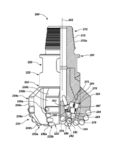
FIG. 2 shows an illustrative earth-boring tool 200 made according to one
embodiment of this disclosure. The earth-boring tool 200 is a polycrystalline
diamond
compact (PDC), fixed-cutter bit having a body 201 that includes a neck or neck
section 210, a shank 220, and a crown or crown section 230. The neck 210 has a
tapered
upper end 212 having threads 212 thereon for connecting the earth-boring tool
200 to a box
end of the drilling assembly 130 (FIG. 1). The shank 220 has a lower vertical
or straight
section 222 that is fixedly connected to the crown 230 at a joint 224. The
crown 230
includes a face or face section 232 that faces the formation during drilling.
The crown 230
includes a number of blades, such as blades 234a, 234b, etc. A typical PDC bit
may
include, for example, from three to seven blades. Each blade has a face (also
referred to as
a "face section-) and a side (also referred to as a "side section-). For
example, blade 234a
has a face 232a and a side 236a, while blade 234b has a face 232b and a side
236b. The
CA 03008387 2018-06-13
WO 2017/106605
PCT/US2016/067106
- 8 -
sides 236a and 236b extend along the longitudinal or vertical axis 202 (e.g.,
an axis of
rotation) of the earth-boring tool 200. Each blade further may further include
a number of
cutters secured thereto. In the particular embodiment of FIG. 2, blade 234a is
shown to
include cutters 238a on a portion of the side 236a and cutters 238b along the
face 232a
while blade 234b is shown to include cutters 239a on the side239a and cutters
239b on the
face 232b.
Still referring to FIG. 2, the earth-boring tool 200 includes one or more
passively
adjustable, aggressiveness-modifying members 250 that extend and retract from
a
surface 252 of the earth-boring tool 200. FIG. 2 shows a passively adjustable,
aggressiveness-modifying member 250 movably placed in a cavity or recess 254
in the
crown section 230. As shown in FIG. 2, the passively adjustable,
aggressiveness-modifying member 250 may be configured as, for example, a pad
or
depth-of-cut control device configured to modify a depth of cut of the cutters
238. An
activation device 260 may be coupled to the passively adjustable,
aggressiveness-modifying member 250 to extend and retract the passively
adjustable,
aggressiveness-modifying member 250 from a surface location 252 on the earth-
boring
tool 200.
In one aspect, the activation device 260 controls the rate of extension and
retraction
of the passively adjustable, aggressiveness-modifying member 250. In another
aspect, the
device 260 extends the passively adjustable, aggressiveness-modifying member
250 at a
first rate and retracts the passively adjustable, aggressiveness-modifying
member 250 at a
second rate. In embodiments, the first rate and second rate may be the same or
different
rates. In another aspect, the rate of extension of the passively adjustable,
aggressiveness-modifying member 250 may be greater than the rate of retraction
As noted
above, the device 260 also is referred to herein as a "rate control device" or
a "rate
controller." In the particular embodiment of the device 260, the passively
adjustable,
aggressiveness-modifying member 250 is directly coupled to the device 260 via
a
mechanical connection or connecting member 256.
In one aspect, the device 260 includes a chamber 270 that houses a double
acting
reciprocating member, such as a piston 280, that sealingly divides the chamber
270 into a
first chamber 272 and a second chamber 274. Both chambers 272 and 274 are
filled with a
hydraulic fluid 278 suitable for downhole use, such as oil. A biasing member,
such as a
spring 284, in the first chamber 272, applies a selected force on the piston
280 to cause it to
CA 03008387 2018-06-13
WO 2017/106605
PCT/US2016/067106
- 9 -
move outward. Since the piston 280 is connected to the passively adjustable,
aggressiveness-modifying member 250, moving the piston outward causes the
passively
adjustable, aggressiveness-modifying member 250 to extend from the surface 252
of the
earth-boring tool 200. In one aspect, the chambers 272 and 274 are in fluid
communication
.. with each other via a first fluid flow path or flow line 282 and a second
fluid flow path or
flow line 286. A flow control device, such as a flow restrictor 285 (e.g., an
orifice plate), a
check valve, or a flow restrictor 285 and a check valve, placed in the fluid
flow line 282,
may be utilized to control the rate of flow of the fluid from chamber 274 to
chamber 272.
Similarly, another flow control device, such as a check valve 287, a flow
restrictor, or a
check valve 287 and a flow restrictor, placed in fluid flow line 286, may be
utilized to
control the rate of flow of the fluid 278 from chamber 272 to chamber 274. The
flow
control devices 285 and 287 may be configured at the surface to set the rates
of flow
through fluid flow lines 282 and 286, respectively.
In one aspect, one or both flow control devices 285 and 287 may include a
variable
control, biasing device, such as a spring, to provide a constant flow rate
from one chamber
to another. Constant fluid flow rate exchange between the chambers 272 and 274
provides
a first constant rate for the extension for the piston 280 and a second
constant rate for the
retraction of the piston 280 and, thus, corresponding constant rates for
extension and
retraction of the passively adjustable, aggressiveness-modifying member 250.
The size of
.. the flow control lines 282 and 286 along with the setting of their
corresponding biasing
devices 285 and 287 define the flow rates through lines 282 and 286,
respectively, and thus
the corresponding rate of extension and retraction of the passively
adjustable,
aggressiveness-modifying member 250. In one aspect, the fluid flow line 282
and its
corresponding flow control device 285 may be set such that when the earth-
boring tool 200
is not in use, i.e., there is no external force being applied onto the
passively adjustable,
aggressiveness-modifying member 250, the biasing member 280 will extend the
passively
adjustable, aggressiveness-modifying member 250 to the maximum extended
position. In
one aspect, the flow control line 282 may be configured so that the biasing
member 280
extends the passively adjustable, aggressiveness-modifying member 250
relatively fast or
suddenly. When the earth-boring tool 200 is in operation, such as during
drilling of a
wellbore, the weight applied to the earth-boring tool 200 may exert an
external force on the
passively adjustable, aggressiveness-modifying member 250. This external force
may
CA 03008387 2018-06-13
WO 2017/106605
PCT/US2016/067106
- 10 -
cause the passively adjustable, aggressiveness-modifying member 250 to apply a
force or
pressure on the piston 280 and thus on the biasing member 284.
In one aspect, the fluid flow line 286 may be configured to allow relatively
slow
flow rate of the fluid from chamber 272 into chamber 274, thereby causing the
passively
adjustable, aggressiveness-modifying member 250 to retract relatively slowly.
As an
example, the extension rate of the passively adjustable, aggressiveness-
modifying
member 250 may be set so that the passively adjustable, aggressiveness-
modifying
member 250 extends from the fully retracted position to a fully extended
position over a
few seconds while it retracts from the fully extended position to the fully
retracted position
over one or several minutes or longer (such as, for example, between two and
five
minutes). It will be noted that any suitable rate may be set for the extension
and retraction
of the passively adjustable, aggressiveness-modifying member 250. In one
aspect, the
device 260 is a passive device that adjusts the extension and retraction of a
passively
adjustable, aggressiveness-modifying member 250 based on or in response to the
force or
pressure applied on the passively adjustable, aggressiveness-modifying member
250.
When the passively adjustable, aggressiveness-modifying member 250 is in a
first
state, the earth-boring tool 200 may exhibit a first aggressiveness, and the
earth-boring
tool 200 may exhibit a second, different aggressiveness when the passively
adjustable,
aggressiveness-modifying member 250 is in a second state. For example, when
the
passively adjustable, aggressiveness-modifying member 250 is in a fully
extended position,
the earth-boring tool 200 may exhibit a least aggressiveness, and the earth-
boring tool may
exhibit a greatest aggressiveness when the passively adjustable,
aggressiveness-modifying
member 250 is in a fully retracted position. Moreover, the passively
adjustable,
aggressiveness-modifying member 250 may automatically adapt the aggressiveness
of the
earth-boring tool 200 responsive to forces inherently acting on the passively
adjustable,
aggressiveness-modifying member 250 (e.g., applied weight, vibrational forces,
reaction
forces from the formation, applied torque) to and between the greatest and
least
aggressivenesses, enabling the earth-boring tool 200 to adaptively react to
drilling
conditions without requiring active intervention from an operator or complex,
active
adjustment-controlling mechanisms.
The passively adjustable, aggressiveness-modifying member 250 may enable the
earth-boring tool 200 to effectively drill the earth formation at lower
applied torque for a
given applied weight (e.g., weight on bit (WOB)). For example, the passively
adjustable,
CA 03008387 2018-06-13
WO 2017/106605
PCT/US2016/067106
- 11 -
aggressiveness-modifying may enable a 5% reduction in applied torque for a
given applied
weight or more. More specifically, the passively adjustable, aggressiveness-
modifying
may enable, for example, a 10% reduction in applied torque for a given applied
weight or
more. As specific, nonlimiting examples, the passively adjustable,
aggressiveness-modifying may enable a 15%, 25%, 30%, 500%, or 60% reduction in
applied
torque for a given applied weight or more.
FIG. 3 shows an another embodiment of a rate control device 300. The device
300
includes a fluid chamber 370 divided by a double acting piston 380 into a
first chamber 372
and a second chamber 374. The chambers 372 and 374 are filled with a hydraulic
fluid 378. A first fluid flow line 382 and an associated flow control device
385 allow the
fluid 378 to flow from chamber 374 to chamber 372 at a first flow rate and a
fluid flow
line 386 and an associated flow control device 387 allow the fluid 378 to flow
from the
chamber 372 to chamber 374 at a second rate. The piston 380 is connected to a
force
transfer device 390 that includes a piston 392 in a chamber 394. The chamber
394 contains
a hydraulic fluid 395, which is in fluid communication with a passively
adjustable,
aggressiveness-modifying member 350. In one aspect, the passively adjustable,
aggressiveness-modifying member 350 may be placed in a chamber 352, which
chamber is
in fluid communication with the fluid 395 in chamber 394. When the biasing
device384
moves the piston 380 outward, it moves the piston 392 outward and into the
chamber 394.
Piston 392 expels fluid 395 from chamber 394 into the chamber 352, which
extends the
passively adjustable, aggressiveness-modifying member 350. When a force is
applied on
to the passively adjustable, aggressiveness-modifying member 350, it pushes
the fluid from
chamber 352 into chamber 394, which applies a force onto the piston 380. The
rate of the
movement of the piston 380 is controlled by the flow of the fluid through the
fluid flow
.. line 386 and flow control device 387.
In the particular configuration shown in FIG. 3, the rate control device 300
is not
directly connected to the passively adjustable, aggressiveness-modifying
member 350,
which enables isolation of the device 300 from the passively adjustable,
aggressiveness-modifying member 350 and allows it to be located at any desired
location
in the earth-boring tool, as described in connection with FIGS. 5 and 6. In
another aspect,
the passively adjustable, aggressiveness-modifying member 350 may be directly
connected
to a cutter 399 or an end of the passively adjustable, aggressiveness-
modifying
member 350 may be made as a cutter. In this configuration, the cutter 399 acts
both as a
CA 03008387 2018-06-13
WO 2017/106605 PCT/US2016/067106
- 12 -
cutter and an extendable and a retractable, passively adjustable,
aggressiveness-modifying
member 350.
FIG. 4 shows a shared rate control device 400 configured to operate more than
one
passively adjustable, aggressiveness-modifying member, such as passively
adjustable,
aggressiveness-modifying members 350a,350b, ... 350n. The rate control device
400 is the
same as shown and described in FIG. 2, except that it is shown to apply force
onto the
passively adjustable, aggressiveness-modifying members 350a, 350b, ... 350n
via an
intermediate device 390, as shown and described in reference to FIG. 3. In the
embodiment of FIG. 4, each of the passively adjustable, aggressiveness-
modifying
members 350a, 350b 350n is housed in separate chambers 352a, 352b ... 352n
respectively. The fluid 395 from chamber 394 is supplied to all chambers 352a,
352b
352n, thereby automatically and simultaneously extending and retracting each
of the
passively adjustable, aggressiveness-modifying members 350a, 350b 350n
based on
external forces applied to each such passively adjustable, aggressiveness-
modifying
members 350a, 350b 350n during drilling. In aspects, the rate control
device 400 may
include a suitable pressure compensator 499 for downhole use. Similarly, any
of the rate
controllers made according to any of the embodiments may employ a suitable
pressure
compensator.
FIG. 5 shows an isometric view of an earth-boring tool 500, wherein a rate
control
.. device 560 is placed in a crown section 530 of the earth-boring tool 500.
The rate control
device 560 is the same as shown in FIG. 2, but is coupled to a passively
adjustable,
aggressiveness-modifying member 550 via a hydraulic connection 540 and a fluid
line 542.
The rate control device 560 is shown placed in a recess 580 accessible from an
outside
surface 582 of the crown section 530. The passively adjustable, aggressiveness-
modifying
.. member 550 is shown placed at a face location section 552 on the face 532,
while the
hydraulic connection 540 is shown placed in the crown 530 between the
passively
adjustable, aggressiveness-modifying member 550 and the rate control device
560. It
should be noted that the rate control device 560 may be placed at any desired
location in
the earth-boring tool 500, including in the shank 520 and neck section 510 and
the
.. hydraulic line 542 may be routed in any desired manner from the rate
control device 560 to
the passively adjustable, aggressiveness-modifying member 550. Such a
configuration
provides flexibility of placing the rate control device substantially anywhere
in the
earth-boring tool 500.
CA 03008387 2018-06-13
WO 2017/106605
PCT/US2016/067106
- 13 -
FIG. 6 shows an isometric view of a earth-boring tool 600, wherein a rate
control
device 660 is placed in a fluid passage 625 of the earth-boring tool 600. In
the particular
tool configuration of FIG. 6, the hydraulic connection 640 is placed proximate
the rate
control device 660. A hydraulic line 670 is run from the hydraulic connection
640 to the
passively adjustable, aggressiveness-modifying member 650 through the shank
620 and the
crown 630 of the earth-boring tool 600. During drilling, a drilling fluid
flows through the
passage 625. To enable the drilling fluid to flow freely through the passage
625, the rate
control device 660 may be provided with a through bore or passage 655 and the
hydraulic
connection device 640 may be provided with a flow passage 645.
FIG. 7 shows an earth-boring tool 700, wherein an integrated passively
adjustable,
aggressiveness-modifying member 755 and rate control device 750 is placed on
an outside
surface of the earth-boring tool 700. In one aspect, the device 750 includes a
rate control
device 760 connected to a passively adjustable, aggressiveness-modifying
member 755. In
one aspect, the device 750 is a sealed unit that may be attached to any
outside surface of
the earth-boring tool 700. The rate control device 760 may be the same as or
different from
the rate control devices described herein in connection with FIGS. 2 through
6. In the
particular embodiment of FIG. 7, the passively adjustable, aggressiveness-
modifying
member 755 is shown connected to a side 720 a of a blade 720 of the earth-
boring tool 700.
The device 750 may be attached or placed at any other suitable location in the
earth-boring
tool 700. Alternatively or in addition thereto, the device 750 may be
integrated into a blade
so that the passively adjustable, aggressiveness-modifying member 755 will
extend toward
a desired direction from the earth-boring tool 700.
FIG. 8 is a cross-sectional view of another embodiment of an earth-boring tool
800
including a passively adjustable, aggressiveness-modifying member 850. The
earth-boring
tool 800, depicted as a roller cone bit, includes a body 802 having three legs
804 depending
from the body 802. A roller cone 806 is rotatably mounted to a bearing pin 816
on each of
the legs 804. Each roller cone 806 may comprise a plurality of cutters 808
(e.g., teeth or
inserts) thereon. The earth-boring tool 800 includes a threaded section 810 at
its upper end
for connection a drill string 118 (see FIG. 1). The earth-boring tool 800 may
include an
internal plenum 812 extending through the body 802 to fluid passageways 814
that extend
from the plenum 812 to a bearing system 828 enabling the roller cones 106 to
rotate about
the bearing pin 816 as they engage with an underlying earth formation.
CA 03008387 2018-06-13
WO 2017/106605
PCT/US2016/067106
- 14 -
The passively adjustable, aggressiveness modifying member 850 may be
integrated
into one or more of the legs 804 of the earth-boring tool 800, such that each
leg 804
including a passively adjustable, aggressiveness modifying member 850 may be
movable
with respect to the body 802. For example, the passively adjustable,
aggressiveness
modifying member 850 may include a bottom portion 820 of the leg 804,
proximate the
bearing pin 816 and separated from the body 802 by an upper portion 822 of the
leg 804.
The bottom portion 820 of the leg 804 may be movable in a direction D at least
substantially parallel to a longitudinal axis 824 (e.g., an axis of rotation)
of the earth-boring
tool 800. The upper portion 822 of the leg 804 may include a recess 826
extending into the
leg 804 toward the body 802, the recess 826 being sized and shaped to receive
a rate
control device 860 therein. The rate control device 860 may be the same as, or
different
from, the rate control devices described herein in connection with FIGS. 2
through 7.
When the earth-boring tool 800 is deployed in a borehole, the passively
adjustable,
aggressiveness modifying member 850 may move between a first, fully extended
state and
a second, fully retracted state in response to forces acting on the passively
adjustable,
aggressiveness modifying member 850. For example, the passively adjustable,
aggressiveness modifying member 850 may dampen vibrations experienced by the
earth-boring tool 850 by moving between a first, lowest longitudinal position
along the
longitudinal axis 824 and second, highest longitudinal position along the
longitudinal
axis 824, dampening vibration experienced by the earth-boring tool 800.
FIG. 9 is a cross-sectional view of a portion of another embodiment of an
earth-boring tool 900 including a passively adjustable, aggressiveness-
modifying
member 950. The earth-boring tool 900, depicted in FIG. 9 as an expandable
reamer, may
include sliding blades 904 positionally retained in a circumferentially spaced
relationship
in a generally cylindrical tubular body 902 of the earth-boring tool. Each
blade 904 may
include cutters 908 secured thereto, the cutters 908 being configured to
engage with, and
remove earth material from, a sidewall of a borehole. The blades 904 are
movable relative
to the tubular body 902 during use of the earth-boring tool 200 between a
retracted position
and an extended position responsive to application of hydraulic pressure.
The passively adjustable, aggressiveness modifying member 950 may be
configured
as one or more of the cutters 908 (e.g., PDC cutting elements, impregnated
inserts, or
inserts of wear resistant material (e.g., metal-matrix-cemented tungsten
carbide)) of the
earth-boring tool 900. A passively adjustable, aggressiveness modifying member
950 may
CA 03008387 2018-06-13
WO 2017/106605
PCT/US2016/067106
- 15 -
be included on each blade 904 in some embodiments. In other embodiments, a
passively
adjustable, aggressiveness-modifying member may be secured to fewer than all
blades 904
of the earth-boring tool 900. The passively adjustable, aggressiveness
modifying
member 950 may be movable in a direction D oriented perpendicular to, or at an
oblique
angle relative to, a longitudinal axis 924 (e.g., an axis of rotation) of the
earth-boring
tool 900. The blade 904 may include a recess 926 extending into the blade 904
toward the
body 902, the recess 926 being sized and shaped to receive a rate control
device 960
therein. The rate control device 960 may be the same as, or different from,
the rate control
devices described herein in connection with FIGS. 2 through 8.
When the earth-boring tool 900 is deployed in a borehole, the passively
adjustable,
aggressiveness modifying member 950 may move between a first, fully extended
state and
a second, fully retracted state in response to forces acting on the passively
adjustable,
aggressiveness modifying member 950. For example, the passively adjustable,
aggressiveness modifying member 950 may transition between an overexposed and
an
underexposed state relative to the other cutters 908 by moving between a
first, outermost
radial position from the longitudinal axis 924 and second, innermost radial
position from
the longitudinal axis 924, responsive to lateral forces from the sidewall of
the borehole.
Thus, in various embodiments, a rate controller may be a hydraulic actuation
device
and may be placed at any desired location in the earth-boring tool or outside
the
earth-boring tool to self-adjust extension and retraction of one or more
passively
adjustable, aggressiveness-modifying members based on or in response to
external forces
applied on the passively adjustable, aggressiveness-modifying members during
drilling of a
wellbore. The passively adjustable, aggressiveness-modifying members may be
located
and oriented independently from the location and/or orientation of the rate
controller in the
.. earth-boring tool. Multiple passively adjustable, aggressiveness-modifying
members may
be inter-connected and activated simultaneously. Multiple passively
adjustable,
aggressiveness-modifying members may also be connected to a shared rate
controller.
In various embodiments, during stick-slip, the passively adjustable,
aggressiveness-modifying members can extend relatively quickly at high
rotational speed
(RPM) of the earth-boring tool when the depth of cut (DOC) of the cutters is
low.
However, at low RPM. when the DOC start increasing suddenly, the pads resist
sudden
inward motion and create a large contact (rubbing) force preventing high DOC.
Limiting
high DOC during stick-slip reduces the high torque build-up and mitigates
stick-slip. In
CA 03008387 2018-06-13
WO 2017/106605
PCT/US2016/067106
- 16 -
various embodiments. the rate controller may allow sudden or substantially
sudden
extension (outward motion) of a passively adjustable, aggressiveness-modifying
member
and limit sudden retraction (inward motion) of the passively adjustable,
aggressiveness-modifying member. Such a mechanism may prevent sudden increase
in the
depth of cut of cutters during drilling. A pressure compensator may be
provided to balance
the pressures inside and outside the cylinder of the rate controller.
Additional, nonlimiting embodiments within the scope of this disclosure
follow:
Embodiment 1: An earth-boring tool, comprising: a body; and a passively
adjustable, aggressiveness-modifying member secured to the body, the passively
adjustable, aggressiveness-modifying member being movable between a first
position in
which the earth-boring tool exhibits a first aggressiveness and a second
position in which
the earth-boring tool exhibits a second, different aggressiveness responsive
to forces acting
on the passively adjustable, aggressiveness-modifying member.
Embodiment 2: The earth-boring tool of Embodiment 1, wherein the passively
adjustable, aggressiveness-modifying member comprises one of a depth-of-cut
limiting
device, a cutting element, a pad, an ovoid, and a leg having a rolling cone
secured to an end
of the leg and wherein the passively adjustable, aggressiveness modifying
member is
movable from the first position at a first longitudinal and radial position
relative to an outer
surface of the body to the second position at a second, different longitudinal
position, radial
position, or both longitudinal and radial position relative to the outer
surface of the body.
Embodiment 3: The earth-boring tool of Embodiment 1 or Embodiment 2, wherein
the first position corresponds to an extended state, the second position
corresponds to a
retracted state, the passively adjustable, aggressiveness-modifying member is
movable
toward the first position at a first rate, and the passively adjustable,
aggressiveness-modifying member is movable toward the second position at a
second,
slower rate.
Embodiment 4: The earth-boring tool of Embodiment 3, wherein the passively
adjustable, aggressiveness-modifying member is biased toward the first
position.
Embodiment 5: The earth-boring tool of Embodiment 3 or Embodiment 4, wherein
the passively adjustable, aggressiveness-modifying member comprises: a
formation-engaging structure; a piston operatively connected to the formation-
engaging
structure, the piston positioned to apply a force on the pad; a biasing member
applying a
force on the piston toward the first position; a fluid chamber divided by the
piston into a
CA 03008387 2018-06-13
WO 2017/106605
PCT/US2016/067106
- 17 -
first fluid chamber and a second fluid chamber; and a first fluid flow path
from the first
fluid chamber to the second fluid chamber that controls movement of the piston
toward the
first position at the first rate and a second fluid flow path from the second
chamber to the
first chamber that controls movement of the piston toward the second position
at the second
.. rate.
Embodiment 6: The earth-boring tool of Embodiment 5, wherein a first check
valve, first flow restrictor, or first check valve and first flow restrictor
in the first fluid flow
path defines the first rate and a second check valve, second flow restrictor,
or second check
valve and second flow restrictor in the second fluid flow path defines the
second rate.
Embodiment 7: The earth-boring tool of Embodiment 5 or Embodiment 6, wherein
the piston comprises a double-acting piston and a fluid acting on a first side
of the
double-acting piston controls at least in part the first rate and a fluid
acting on a second,
opposite side of the double-acting piston controls at least in part the second
rate.
Embodiment 8: The earth-boring tool of any one of Embodiments 5 through 7,
wherein the piston is operatively coupled to the formation-engaging structure
by one of: a
direct mechanical connection and via a fluid.
Embodiment 9: The earth-boring tool of any one of Embodiments 1 through 8,
wherein the earth-boring tool is a rolling cone drill bit or a hybrid bit and
the passively
adjustable, aggressiveness-modifying member is located on a leg extending from
the body
of the rolling cone drill bit or hybrid bit toward a rolling cone secured to
an end of the leg,
the passively adjustable, aggressiveness-modifying member enabling the leg to
dampen
vibration as the rolling cone engages with an underlying earth formation.
Embodiment 10: The earth-boring tool of Embodiment 9, further comprising an
additional passively adjustable, aggressiveness-modifying member on each other
leg
extending from the body of the rolling cone drill bit or hybrid bit.
Embodiment 11: The earth-boring tool of any one of Embodiments 1 through 8,
wherein the earth-boring tool is a reamer and the passively adjustable,
aggressiveness-modifying member is located on a blade of the reamer, the
passively
adjustable, aggressiveness-modifying member being configured to modify a depth
of cut of
cutting elements secured to the blade of the reamer in response to forces
applied to the
passively adjustable, aggressiveness-modifying member as the cutting elements
engage
with an earth formation.
CA 03008387 2018-06-13
WO 2017/106605
PCT/US2016/067106
- 18 -
Embodiment 12: The earth-boring tool of Embodiment 11, further comprising an
additional passively adjustable, aggressiveness-modifying member on each other
blade of
the reamer.
Embodiment 13: A method of passively adjusting an aggressiveness of an
earth-boring tool, comprising: causing a force to be exerted on a passively
adjustable,
aggressiveness-modifying member secured to a body; and moving the passively
adjustable,
aggressiveness-modifying member from a first position in which the earth-
boring tool
exhibits a first aggressiveness to a second position in which the earth-boring
tool exhibits a
second, different aggressiveness responsive to causing the force to act on the
passively
adjustable, aggressiveness-modifying member.
Embodiment 14: The method of Embodiment 13, wherein moving the passively
adjustable, aggressiveness-modifying member from the first position to the
second position
comprises increasing the aggressiveness of the earth-boring tool by retracting
the passively
adjustable, aggressiveness-modifying member from an extended position, toward
the body,
to a retracted position.
Embodiment 15: The method of Embodiment 14, further comprising subsequently
decreasing the aggressiveness of the earth-boring tool by extending the
passively
adjustable, aggressiveness-modifying member from the retracted position, away
from the
body, to the extended position.
Embodiment 16: The method of Embodiment 15, wherein retracting the passively
adjustable, aggressiveness-modifying member from the extended position to the
retracted
position comprises retracting the passively adjustable, aggressiveness-
modifying member
from the extended position to the retracted position at a first rate and
wherein extending the
passively adjustable, aggressiveness-modifying member from the retracted
position to the
extended position comprises extending the passively adjustable, aggressiveness-
modifying
member from the retracted position to the extended position at a second,
faster rate.
Embodiment 17: The method of Embodiment 15 or Embodiment 16, wherein
extending the passively adjustable, aggressiveness-modifying member from the
retracted
position to the extended position comprises enabling a biasing member biasing
the
passively adjustable, aggressiveness-modifying member toward the extended
position to
extend the passively adjustable, aggressiveness-modifying member from the
retracted
position to the extended position.
CA 03008387 2018-06-13
WO 2017/106605
PCT/US2016/067106
- 19 -
Embodiment 18: The method of any one of Embodiments 13 through 17, wherein
the passively adjustable, aggressiveness-modifying member comprises one of a
depth-of-cut limiting device, a cutting element, a pad, an ovoid, and a leg
having a rolling
cone secured to an end of the leg and wherein moving the passively adjustable,
aggressiveness-modifying member from the first position to the second position
comprises
moving the passively adjustable, aggressiveness modifying member from a first
longitudinal and radial position relative to an outer surface of the body to a
second,
different longitudinal position, radial position, or both longitudinal and
radial position
relative to the outer surface of the body.
Embodiment 19: The method of any one of Embodiments 13 through 18, wherein
the earth-boring tool is a rolling cone drill bit or a hybrid bit and the
passively adjustable,
aggressiveness-modifying member is located on a leg extending from the body of
the
rolling cone drill bit or hybrid bit toward a rolling cone secured to an end
of the leg, and
wherein moving the passively adjustable, aggressiveness-modifying member from
the first
position to the second position comprises dampening vibration experienced by
the leg as
the rolling cone engages with an underlying earth formation.
Embodiment 20: The method of any one of Embodiments 13 through 18, wherein
the earth-boring tool is a reamer and the passively adjustable, aggressiveness-
modifying
member is located on a blade of the reamer, and wherein moving the passively
adjustable,
aggressiveness-modifying member from the first position to the second position
comprises
modifying a depth of cut of cutting elements secured to the blade of the
reamer in response
to forces applied to the passively adjustable, aggressiveness-modifying member
as the
cutting elements engage with an earth formation.
While certain illustrative embodiments have been described in connection with
the
figures, those of ordinary skill in the art will recognize and appreciate that
the scope of this
disclosure is not limited to those embodiments explicitly shown and described
in this
disclosure. Rather, many additions, deletions, and modifications to the
embodiments
described in this disclosure may be made to produce embodiments within the
scope of this
disclosure, such as those specifically claimed, including legal equivalents.
In addition,
features from one disclosed embodiment may be combined with features of
another
disclosed embodiment while still being within the scope of this disclosure, as
contemplated
by the inventors.