Note: Descriptions are shown in the official language in which they were submitted.
CA 03008658 2018-06-15
WO 2017/100926
PCT/CA2016/051481
SYRINGES WITH RETRACTABLE NEEDLE
BACKGROUND
[0001] Syringes with retractable needles can have the advantage of moving the
needle
out from exposure once the injection has been performed, potentially
presenting a particular
interest for disposal, or otherwise for use by persons who do not have a
profound medical
training. International patent application publication W02014096957 presents
various
embodiments of syringes with retractable needles.
[0002] While existing technology was found satisfactory to a certain
extent, there
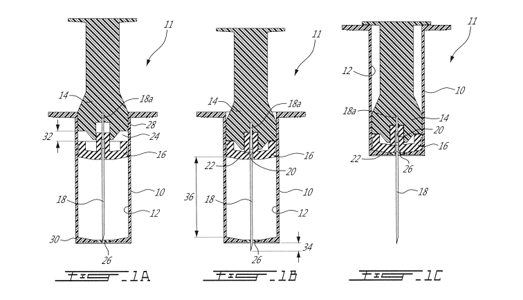
remained room for improvement.
SUMMARY
[0003] In accordance with one aspect, there is provided a syringe having
a plunger body
and a plunger seal both independently slidingly engaged within a cavity of a
barrel for
movement along a common longitudinal axis, and a needle anchored to the
plunger body
and extending across the plunger seal, the needle having an inlet aperture
allowing fluid flow
communication into an internal conduit of the needle, the barrel having a
reservoir for
receiving a medical fluid, the reservoir extending between the plunger seal
and a bottom, the
bottom being closed by a septum, wherein to proceed with injection, the
plunger body is slid
toward the plunger seal along a penetration span, during which movement the
needle
punctures the septum and protrudes from the bottom without injecting medical
fluid, until the
plunger body engages the plunger seal, after which the plunger body and the
plunger seal
are collectively moved to inject the medical fluid until the plunger seal
reaches the bottom.
[0004] In accordance with another aspect, there is provided a syringe
having a plunger
having a plunger seal slidingly engaged within a cavity of a barrel, and a
needle anchored to
the plunger, the barrel having a reservoir for receiving a medical fluid, the
reservoir
extending between the plunger seal and a bottom, the bottom being closed by a
septum, the
needle having a lateral aperture allowing fluid flow communication between the
reservoir and
an internal conduit of the needle, wherein to proceed with injection, the
plunger seal and the
anchored needle are collectively moved along an axis of the syringe toward the
bottom to
inject the medical fluid until the plunger seal reaches the bottom, wherein
the lateral aperture
CA 03008658 2018-06-15
WO 2017/100926
PCT/CA2016/051481
- 2 -
of the needle extends along a given axial length immediately below the plunger
seal in a
manner remain exposed to the reservoir until the plunger seal has reached the
bottom.
[0005] In accordance with another aspect, there is provided a syringe
having a plunger
anchor to which a needle is anchored and a plunger seal both slidingly engaged
within a
cavity of a barrel, and a plunger actuator having at least two elastic arms
slidingly engaged
around the barrel, the arms being biased to a radially inward position and
prevented by the
barrel, the barrel having a septum seal at a bottom and an open top, wherein
to proceed with
injection, the plunger actuator is pulled upwardly until the arms are freed
from the barrel, at
which points the arms are freed and move to the radially inward position, and
the plunger
actuator can be pushed downwardly to engage the arms into the barrel via the
open top,
until they engage the plunger anchor and become operable to push the needle
across the
septum.
[0006] Many further features and combinations thereof concerning the present
improvements will appear to those skilled in the art following a reading of
the instant
disclosure.
DESCRIPTION OF THE FIGURES
[0007] In the figures,
[0008] Figs 1A, 1B and 10 is a sequence of three cross-sectional views of
a first
embodiment of a syringe, in which the syringe is shown in different
configurations;
[0009] Figs 2A and 2B show a sequence of 7 cross-sectional views of a second
embodiment of a syringe, showing sequential configurations of the syringe
during operation;
[0010] Fig. 3A is a side elevation view of a third embodiment of a
syringe, with Fig. 3B
being a cross-section thereof taken along cross-section lines 3B-3B of Fig.
3A;
[0011] Fig. 30 is an oblique view of the syringe of Fig. 3A, shown with a
stop;
[0012] Fig. 3D is a fragmented, oblique cross-sectional view of the syringe
of Fig. 3A
shown at a later configuration of use;
CA 03008658 2018-06-15
WO 2017/100926
PCT/CA2016/051481
- 3 -
[0013] Fig. 4 is a sequence of 4 cross-sectional views of a fourth
embodiment of a
syringe, showing sequential configurations of the syringe during operation;
[0014] Fig. 5A and 5B show a sequence of 8 cross-sectional views of a fifth
embodiment
of a syringe, showing sequential configurations of the syringe during
operation;
[0015] Fig. 50 is an oblique view of a component of the syringe of Fig. 5A
and 5B.
DETAILED DESCRIPTION
[0016] The figures show syringes with a confined needle, a reservoir with
a prefilled
medical fluid, and a plunger to which the needle is anchored. The plunger is
in two parts: a
body and a seal.
[0017] A first embodiment of a syringe is shown in Figs. 1A to 10. The syringe
11 has a
barrel 10 defining a reservoir 12 containing the medical fluid. A plunger body
14 and a
plunger seal 16 can independently slide back and forth along the longitudinal
axis of the
barrel 10. A needle 18 is anchored in a head of the plunger body 14, at 18a
and passes
through the plunger seal 16 in a passage 20 defined in the plunger seal 16,
along the
longitudinal axis of displacement. The needle 18 has an inlet 22 as shown.
More specifically,
the needle 18 is provided in the form of a straight metal tube having a first
end anchored in
the plunger body 14, the straight metal tube projecting from the plunger body
14 along the
longitudinal axis of displacement and leading to a free end having a beveled
tip. The inlet 22
is defined transversally across a portion of the metal tube, and allows fluid
flow
communication between the outside of the metal tube and an internal conduit
inside the
metal tube leading to the free end for medical fluid injection.
[0018] Fig. 1A shows the syringe 11 in its initial configuration, prior
to injection. In the
initial configuration, the plunger seal 16 is positioned at an intermediary
position along the
longitudinal axis of displacement whereas the head of the plunger body 14 is
positioned at a
first end 28 of the barrel 10. A spacing 24 is provided between the plunger
body 14 and the
plunger seal 16. The barrel 10 has a second end 30 opposite the first end 28.
A septum 26
initially closes the second end, and the medical fluid is trapped between the
plunger seal 16,
the peripheral wall of the barrel 10, and the septum 26. The plunger seal 16
has a cylindrical
CA 03008658 2018-06-15
WO 2017/100926
PCT/CA2016/051481
- 4 -
recess surrounding the needle 18 and the inlet 22. This cylindrical recess, as
well as the
internal needle conduit, are also filled with medical fluid in the initial
position.
[0019] To proceed to injection, the second end 30 of the barrel 10, and the
septum 26, are
positioned against the skin of the patient. The plunger body 14 is then
activated to move
along the longitudinal axis of displacement, moving the anchored needle 18
with it. The
plunger body 14 will first advance along a penetration span 32 corresponding
to the
longitudinal length of the spacing 24, and the free end of the needle 18 will
pierce the
septum 26 and penetrate into the body of the patient. During this movement,
medical fluid is
free to move into the cylindrical recess, across the inlet 22, and be injected
into the patient.
However, the volume of the reservoir 22 remains the same during this movement,
and fluid
is not pushed across the needle aperture 22 and into the patient until the
plunger body 14
engages the plunger seal 16 in the configuration shown in Fig. 1B. This can
allow the needle
tip to reach a given penetration distance 34 beneath the skin of the patient
prior to beginning
injection.
[0020] In an alternate embodiment, the internal needle conduit is filled
with medical fluid in
the initial position, but the plunger seal 16 does not have a cylindrical
recess and rather
abuts against the needle inlet 22 and an additional portion of the needle
under the needle
inlet, in a manner that the needle inlet 22 is sealed by the plunger seal 16
and remains
sealed by the plunger seal as the plunger body 14 is moved along the
penetration distance.
The needle inlet 22 only becomes exposed to the reservoir 12 once the plunger
body 14 has
been moved along the penetration span 32 and needle inlet 22 has crossed the
plunger seal
16.
[0021] Referring now to Figs. 1B and 10, once the plunger body 14 has
reached and
abuts against the plunger seal 16, further movement of the plunger body 14
will move not
only the plunger body 14, but also the plunger seal 16, which, in turn,
confines the volume of
the reservoir 12. The volume-confining action entrains movement of the medical
fluid across
the needle inlet 22, along the needle conduit, and out the needle tip into the
patient, as the
plunger body 14 and plunger seal 16 are collectively moved along an injection
span 36 from
the position shown in Fig. 1B to the position shown in Fig. 10. In the
position shown in
Fig. 10, the medical fluid has been completely injected into the patient's
body.
CA 03008658 2018-06-15
WO 2017/100926
PCT/CA2016/051481
- 5 -
[0022] It will be noted here that in the position shown in Fig. 10, the
volume-confining face
of the plunger seal 16 closely matches the shape of the bottom of the barrel,
and the position
of the aperture 22 can be adjusted in a manner that the aperture 22 remains
exposed to the
medical fluid until the very end of the movement (the point where the plunger
seal 16 meets
the septum 26 and the bottom of the barrel 10). Accordingly, the volume of
medical fluid
which remains undispensed after the injection operation can be minimized.
[0023] From that position, the movement of the plunger body 14 is
reversed, pulling the
needle 18 back into the reservoir 12 (not shown). During the reversed
movement, the friction
between the plunger seal 16 and the barrel 10 is greater than the friction
between the
plunger seal 16 and the needle 18, and the plunger seal 16 will typically
remain in its fully
deployed position as the needle 18 is retracted. Once the needle aperture 22
has moved
across the plunger seal 16 and is exposed to the atmosphere, the internal
needle conduit
remains at atmospheric pressure.
[0024] Figs. 2A and 2B show a similar embodiment along successive operation
steps 1
to 7. Two differences with the embodiment of Fig. 1A to 10 will be discussed.
A first one of
these differences is that the bottom of the barrel 110 has a projecting neck
140 which
projects peripherally opposite the reservoir 112. The projecting neck 140
engages the skin
142 of the patient as shown in step 2, which can cause a puckering, or
bulging, of the
skin 142 as shown. This puckering or bulging of the skin 142 can be
particularly useful in
embodiments where the syringe 111 is designed for injection at sub-cutaneous
depths. A
second one of these differences is the presence of a rib 144 protruding
transversally
inwardly from the barrel 110 near the upper end 128, and a corresponding
female feature
146, shown here in the form of a groove or channel, provided in the head of
the plunger
body 114. When the plunger body 114 is fully retracted, such as shown at step
7, the rib 144
engages the female peripheral channel 146 provided around the head of the
plunger body
114, effectively snapping the plunger body 114 in the fully retracted
position.
[0025] It will be noted that the reservoir 112 generally has a
cylindrical shape in this
embodiment. The exact volume of a specific design which departs from a
cylindrical shape
can be calculated using a computer assisted drawing software, for instance.
Nonetheless, to
evaluate the general principles, we will look into an example cylindrical
shape. A cylindrical
CA 03008658 2018-06-15
WO 2017/100926
PCT/CA2016/051481
- 6 -
volume can be calculated by the equation V = Trr2h where r is the radius and h
is the height.
In this example, it will be understood that the reservoir can be designed in a
manner for the
injecting action of a given volume of medical fluid to be confined within a
given height span
of the reservoir. Indeed, this can be achieved by adapting the radius r of the
reservoir
accordingly. A reservoir having a larger radius, for a given volume, can be
used for sub-
cutaneous injection, whereas a reservoir having a smaller radius and a greater
height, for a
given volume, can be used for intramuscular injection, for instance. The
penetration span
132 can be adjusted independently from the injection span 134 as can be
understood from
the above. The design shown in Figs. 2A and 2B is adapted for sub-cutaneous
injection.
[0026] An example of a design adapted for intra-muscular injection is shown in
Figs. 3A,
3B and 30. Referring to Fig. 3A, similar features to those shown in previously
described
designs will be recognized. Several differences can also be observed. For
instance, the
septum 226 is provided here in a thicker form and in a shape which snugly fits
and abuts
against a neck 250 provided in the bottom of a plastic shell of the barrel
210. The plunger
body 214 also has a peripheral wall 252 connected to its tip 254. When the
syringe 211 is in
the initial position, such as shown in Figs. 3A and 3B, a stop 256, which can
be provided in
the form of a transversally snapping collar for instance, can be provided
around the barrel
210, to prevent accidental puncturing of the septum 226 should pressure be
applied to the
plunger body 214 without the intention of injecting. More specifically, the
stop 256 is
engaged between corresponding features 258, 260 provided in the peripheral
wall of the
plunger body 214 and a footer 262 of the barrel 210, respectively. To proceed
with injection,
the stop 256 is removed by pulling it transversally. Fig. 3B shows the syringe
with the
stop 256 removed, ready for injection. This embodiment also features two
annular ribs 264,
266 in the upper portion of the barrel 210, between which the head 268 of the
plunger body
214 can be retracted and trapped after the injection operation. Indeed, the
lower rib 264, the
head 268, or both, can be made of a resilient material to provide a snapping
function. Fig.
3D shows the plunger seal 216 approaching the septum 226 and nearing the end
of the
injection. The aperture 222 in the needle 218 can be seen to extend across the
remaining
gap between the plunger seal 216 and the septum 226, allowing injection of the
medical fluid
all the way until the plunger seal 216 snugly engages the septum 226.
CA 03008658 2018-06-15
WO 2017/100926
PCT/CA2016/051481
- 7 -
[0027] It will be understood that embodiments of the syringe can be
provide with an
automatically retracting feature which biases the plunger body to the
retracted position in a
manner that once the injection has been completed, the plunger body can be
activated to
move to its fully retracted position in the absence of an external force (e.g.
when the volume-
confining force applied by the user to proceed with injection has been
discontinued).
[0028] An example of a syringe 311 having an automatic retraction feature is
provided in
Fig. 4. More specifically, a compressed spring 370 is housed in an upper
annular cavity 372
between a core 374 of the plunger body 314 and the peripheral wall 352. A
mechanism is
used to maintain the spring 370 in the compressed state until the injection
has been
completed. In this embodiment, the mechanism is provided in the form of
retainer clasps 376
which project downwardly from the top of the plunger body 314 into the cavity
372. The
retainer clasps have a sloping face 378 extending downwardly. The sloping
faces 378 are
designed to engage an upper edge 380 of the barrel 310 when the plunger body
314 has
been fully pushed downwardly, in a manner that the barrel 310 reactively
pushes the retainer
clasps 376 inwardly, which frees the spring 370 from the retainer clasps 376.
At this point,
the retainer clasps 376 no longer retain the spring 370 in its compressed
state and the
spring 370 is free to extend, exerting a biasing force between the plunger
body 314 and the
barrel 310, which moves the plunger body 314 back into the fully retracted
state in the
absence of an external force, such as when the volume-confining force exerted
by the user
is discontinued.
[0029] Still another example of a syringe is provided in Fig. 5A and 5B.
This embodiment
is similar to the embodiment of Fig. 4. However, the plunger body has an
engagement
component 490 which has a shape shown in Fig. 50, having a base 492 and
circumferentially interspaced arms 494 projecting longitudinally from the base
492 . The
engagement component 490 is made of a resilient material. Initially, the arms
494 are moved
outwardly and are positioned to surround the barrel 410. The engagement
component 490 is
housed within a cap 496. The cap 496 can be pushed downwardly around the
barrel 410,
such as shown on the left hand side of Fig. 5A. This initial configuration
avoids unintentional
activation of the needle 418 should a compressing force be unintentionally
exerted between
the cap and the barrel. To proceed with injection, the cap 496 is first pulled
upwardly until the
CA 03008658 2018-06-15
WO 2017/100926
PCT/CA2016/051481
- 8 -
arms 492 are freed from engagement with the barrel 410. At that stage, the
arms 494 revert
to their original shape, and move radially inward. The arms 494 can then be
pushed
downwardly inside the barrel 410 by exerting a compressive force between the
cap 496 and
the barrel 410. The arms eventually engage the remainder of the plunger body
414 to which
the needle 418 is anchored, at which point pushing the cap 496 downwardly will
have the
effect of pushing the needle 418 downwardly, puncturing the septum 426,
continuing on the
penetration span, and subsequently injecting the medical fluid. The arms 494
are provided
with retaining clasps 498 at their tips which become engaged with the
remainder of the
plunger body 414, in a manner that once injection is terminated, the needle
418 can be
retracted by pulling the cap 496 back up.
[0030] PRE-CLINICAL TRIAL
[0031] A preliminary pre-clinical trial was performed to assess the
functionality a syringe
which displaces the needle tip more deeply into the body as the medical fluid
is being
injected. More specifically, the trial was performed using a syringe such as
shown in Fig. 3A,
3B and 3C.
[0032] Two -10 kg Landrace Yorkshire Cross pigs received Infra Muscular (IM)
injections
of 500 pL of India ink in marked locations. Three injections were performed
with a standard 1
cc tuberculin syringe (AIM) and 3 injections were performed with a syringe
with a retractable
needle which was fixedly mounted to the plunger (BIM). One animal was
sacrificed at an
early (E) time point (t = 1 hour), the other was sacrificed at a later (L)
time point (t = 5 hours).
The injections sites were evaluated on a standard scoring system with high
quality digital
pictures taken at a fixed distance for digital analysis. The injection sites
were then excised
for histological evaluation. The external injection site evaluation
demonstrated that all
injection sites were normal. Table 1, below, presents the mean summary data
sheet for the
excised injection site evaluation.
CA 03008658 2018-06-15
WO 2017/100926 PCT/CA2016/051481
- 9 -
Injection Site Degree Intensity Mean Volume (mm3) SD
A-IM-L 3.00 3.00 9,754.04 5,529.86
B-IM-L 3.00 3.00 15,970.25 4,037.75
A-IM-E 3.00 3.00 5,792.70 3,784.87
B-IM-E 2.00 2.00 6,456.94 5,948.85
Table 1 : Mean summary data sheet
[0033] In the test sample sacrificed at the later time point, the mean
volume of injection
was significantly higher for the syringe with the retractable needle than for
the standard 1 cc
tuberculin syringe.
[0034] In this description, specific embodiments are described with reference
to
associated figures for the purpose of providing example ways of embodying the
invention(s).
The invention(s) is/are not to be construed as being limited in scope to the
specific
embodiments described.