Note: Descriptions are shown in the official language in which they were submitted.
CA 03009265 2018-06-20
WO 2017/114746 PCT/EP2016/082357
ELECTROCHEMICAL-BASED ANALYTICAL TEST STRIP
WITH ELECTRODE VOLTAGE SENSING CONNECTIONS
AND HAND-HELD TEST METER FOR USE THEREWITH
BACKGROUND OF THE INVENTION
[0001] Field of the Invention
[0002] The present invention relates, in general, to medical devices and,
in
particular, to electrochemical-based analytical test strips and hand-held test
meters for use therewith.
[0003] Description of Related Art
[0004] The determination (e.g., detection and/or concentration
measurement) of
an analyte in, or a characteristic of, a fluid sample is of particular
interest in the
medical field. For example, it can be desirable to determine glucose, ketone
bodies, cholesterol, lipoproteins, triglycerides, acetaminophen, hematocrit
and/or HbA1c concentrations in a sample of a bodily fluid such as urine,
blood,
plasma or interstitial fluid. Such determinations can be achieved using
analytical
test strips, based on, for example, visual, photometric or electrochemical
techniques in conjunction with a hand-held test meter. Conventional
electrochemical-based analytical test strips are described in, for example,
U.S.
Patent Nos. 5,708,247 and 6,284,125, each of which is hereby incorporated in
full by reference.
BRIEF DESCRIPTION OF THE DRAWINGS
[0005] The accompanying drawings, which are incorporated herein and
constitute part of this specification, illustrate presently preferred
embodiments of
the invention, and, together with the general description given above and the
detailed description given below, serve to explain features of the invention,
in
which:
CA 03009265 2018-06-20
WO 2017/114746
PCT/EP2016/082357
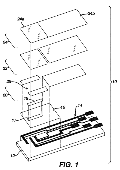
FIG. 1 is a simplified exploded perspective view of an
electrochemical-based analytical test strip according to an embodiment of the
present invention;
FIG. 2 is a simplified top view of a patterned conductor layer and substrate
layer of the electrochemical-based analytical test strip of FIG. 1 with the
location
of an enzymatic reagent layer depicted by dashed lines;
FIG. 3 is a simplified top view of a hand-held test meter according to an
embodiment of the present invention;
FIG. 4 is a simplified block diagram of the hand-held test meter of FIG. 4;
and
FIG. 5 is a simplified schematic diagram of an automatic bias drive
adjustment circuit block for a single working electrode (WE) and reference
electrode (REF) pair as can be employed in embodiments of the present
invention.
DETAILED DESCRIPTION OF ILLUSTRATIVE EMBODIMENTS
[0006] The
following detailed description should be read with reference to the
drawings, in which like elements in different drawings are identically
numbered.
The drawings, which are not necessarily to scale, depict exemplary
embodiments for the purpose of explanation only and are not intended to limit
the
scope of the invention. The detailed description illustrates by way of
example,
not by way of limitation, the principles of the invention. This description
will
clearly enable one skilled in the art to make and use the invention, and
describes
several embodiments, adaptations, variations, alternatives and uses of the
invention, including what is presently believed to be the best mode of
carrying
out the invention.
[0007] As used
herein, the terms "about" or "approximately" for any numerical
values or ranges indicate a suitable tolerance that allows a component or
collection of components to function for its intended purpose as described
herein.
- 2 -
CA 03009265 2018-06-20
WO 2017/114746 PCT/EP2016/082357
[0008] An electrochemical-based analytical test strip for use with a hand-
held
test meter in the determination of an analyte (such as glucose) in a bodily
fluid
sample (e.g., a whole blood sample) includes an electrically insulating base
layer, a patterned electrically conductive layer disposed on the electrically
insulating base layer, an enzymatic reagent layer, a patterned spacer layer;
and
a top layer. The patterned electrically conductive layer includes at least one
electrode (for example, two electrodes, namely a working electrode and a
reference electrode), at least one electrode voltage sensing connection
configured to sense voltage at the least one electrode (e.g., a working
electrode
voltage sensing connection and a reference electrode voltage sensing
connection), at least one electrode track, and at least one electrode voltage
sensing connection track. Moreover, the electrode voltage sensing connections
are configured for operable communication of a sensed electrode voltage to an
associated hand-held test meter via the at least one electrode voltage sensing
connection.
[0009] Electrochemical-based analytical test strips according to
embodiments of
the present invention are beneficial in that the electrode voltage sensing
connections and electrode voltage sensing connection tracks can be employed
by an associated hand-held test meter (described herein) to measure
deleterious
voltage drop(s) on the electrochemical-based analytical test strip. Such
measured voltage drop(s) can then be employed by the hand-held test meter to
automatically (for example, dynamically) adjust a voltage bias drive(s)
applied to
the electrochemical-based analytical test strip by the hand-held test meter.
Such
automatic adjustments result in the electrode track resistance and dimensional
tolerance being beneficially less critical to accurate use of embodiments of
electrochemical-based analytical test strips and hand-held test meters of the
present invention.
[0010] FIG. 1 is a simplified exploded perspective view of an
electrochemical-based analytical test strip 10 according to an embodiment of
the
- 3 -
CA 03009265 2018-06-20
WO 2017/114746 PCT/EP2016/082357
present invention. FIG. 2 is a simplified top view of a patterned conductor
layer
and substrate layer of electrochemical-based analytical test strip 10 with the
location of an enzymatic reagent layer depicted by dashed lines. FIG. 3 is a
simplified top view of a hand-held test meter 100 according to an embodiment
of
the present invention. FIG. 4 is a simplified block diagram of hand-held test
meter 100. FIG. 5 is a simplified schematic diagram of an electrode bias
adjustment circuit block for a single working electrode (WE) and reference
electrode (REF) pair as can be employed in hand-held test meter embodiments
of the present invention.
[0011] Referring to FIGs. 1 and 2, electrochemical-based analytical test
strip 10
for the determination of an analyte (such as glucose) in a bodily fluid sample
(for
example, a whole blood sample) includes an electrically-insulating base layer
12,
a patterned electrically conductive layer 14, a patterned insulation layer 16
with
opening 17 therethrough, an enzymatic reagent layer 18, a patterned spacer
layer 20, and a top layer consisting of a hydrophilic sub-layer 22 and a top
tape
24 with portions 24a and 24b.
[0012] In the embodiment of FIGs. 1 and 2, at least the patterned spacer
layer
and top layer define a sample-receiving chamber 25 within
electrochemical-based analytical test strip 10.
[0013] An electrochemical-based analytical test strip 10 is configured
for use with
a hand-held test meter (e.g., a hand-held test meter according to embodiments
of the present invention and described herein) in the determination of an
analyte
in a bodily fluid sample, the electrochemical-based analytical test strip.
See, for
example, the hand-held test meter described with respect to FIGs 3, 4 and 5.
[0014] Electrically-insulating base layer 12 can be any suitable
electrically-insulating base layer known to one skilled in the art including,
for
example, a nylon base layer, a polycarbonate base layer, a polyimide base
layer,
a polyvinyl chloride base layer, a polyethylene base layer, a polypropylene
base
- 4 -
CA 03009265 2018-06-20
WO 2017/114746 PCT/EP2016/082357
layer, a glycolated polyester (PETG) base layer, or a polyester base layer.
The
electrically-insulating base layer can have any suitable dimensions including,
for
example, a width dimension of about 5 mm, a length dimension of about 27 mm
and a thickness dimension of about 0.5 mm.
[0015] Electrically-insulating base layer 12 provides structure to
electrochemical-based analytical test strip 10 for ease of handling and also
serves as a base for the application (e.g., printing or deposition) of
subsequent
layers (e.g., a patterned electrically conductor layer and an enzymatic
reagent
formed by ink jet printing or screen printing of an enzymatic reagent layer
according to the present invention and described herein).
[0016] Patterned electrically conductive layer 14 is disposed on the
electrically-
insulating base layer 12 and includes a first electrode 14a, a second
electrode
14b and a third electrode 14c. First electrode 14a, second electrode 14b and
third electrode 14c can be, for example, configured as a counter/reference
electrode, a first working electrode and a second working electrode,
respectively.
Therefore, the second and third electrodes are also referred to herein as
working
electrodes 14b and 14c and the first electrode as counter electrode 14a.
Although, for the purpose of explanation only, electrochemical-based
analytical
test strip 10 is depicted as including a total of three electrodes,
embodiments of
electrochemical-based analytical test strips, including embodiments of the
present invention, can include any suitable number of electrodes.
[0017] Patterned electrically conductive layer 14 also includes a first
electrode
voltage sensing connection 14d, a second electrode voltage sensing connection
14e and a third electrode voltage sensing connection 14f configured to sense
electrode voltage at the counter/reference electrode, first working electrode
and
second working electrode respectively.
- 5 -
CA 03009265 2018-06-20
WO 2017/114746 PCT/EP2016/082357
[0018] Patterned electrically conductive layer 14 also includes a
plurality of
electrode connection tracks 14g configured for operable communication of a
sensed electrode voltage to a hand-held test meter.
[0019] Patterned electrically conductive layer 14 can be formed of any
suitable
conductive material including, for example, electrically conducting carbon-
based
materials including carbon inks. It should be noted that patterned
electrically
conductive layers employed in electrochemical-based analytical test strips
according to embodiments of the present invention can take any suitable shape
and be formed of any suitable materials including, for example, metal
materials
and conductive carbon materials.
[0020] Referring to FIGs. 1 and 2, the disposition of first electrode
14a, second
electrode 14b and third electrode 14c and enzymatic reagent layer 18 are such
that electrochemical-based analytical test strip 10 is configured for the
electrochemical determination of an analyte (such as glucose) in a bodily
fluid
sample (such as a whole blood sample) that has filled sample-receiving chamber
25.
[0021] Enzymatic reagent layer 18 is disposed on at least a portion of
patterned
electrically conductor layer 14 (see FIG. 2 wherein the disposition of
enzymatic
reagent layer 18 is depicted by dashed lines). Once apprised of the present
disclosure, one skilled in the art will recognize that a variety of suitable
enzymatic
reagents are known to one skilled in the art. Further details regarding
reagent
layers in general, and electrochemical-based analytical test strips in
general, are
in U.S. Patent Nos. 6,241,862 and 6,733,655, the contents of which are hereby
fully incorporated by reference.
[0022] Referring to FIGs. 1 and 2, patterned insulation layer 16 can be
formed of
any suitable electrically-insulating dielectric material including
commercially
available screen-printable dielectric inks.
- 6 -
CA 03009265 2018-06-20
WO 2017/114746 PCT/EP2016/082357
[0023] Patterned spacer layer 20 can be formed, for example, from a
screen-printable pressure sensitive adhesive commercially available from
Apollo
Adhesives, Tamworth, Staffordshire, UK. In the embodiment of FIG. and 2,
patterned spacer layer 20 defines outer walls of the sample-receiving chamber
25. Patterned spacer layer 20 can have a thickness of, for example,
approximately 110 microns, be electrically nonconductive, and be formed of a
polyester material with top and bottom side acrylic-based pressure sensitive
adhesive.
[0024] Top layer 24 can be, for example, a clear film with hydrophilic
properties
that promote wetting and filling of electrochemical-based analytical test
strip 10
by a fluid sample (e.g., a whole blood sample). Such clear films are
commercially available from, for example, 3M of Minneapolis, Minnesota U.S.A.
and Coveme (San Lazzaro di Savena, Italy). Top layer 24 can be, for example, a
polyester film coated with a surfactant that provides a hydrophilic contact
angle
less than 10 degrees. Top layer 24 can also be a polypropylene film coated
with
a surfactant or other surface treatment. In such a circumstance, the
surfactant
coating serves as hydrophilic sub-layer 22. Top layer 24 can have a thickness,
for example, of approximately 100 m.
[0025] Electrochemical-based analytical test strip 10 can be
manufactured, for
example, by the sequential aligned formation of the layers depicted in FIG 1.
Any suitable techniques known to one skilled in the art can be used to
accomplish such sequential aligned formation, including, for example, screen
printing, ink-jet printing, photolithography, photogravure, chemical vapour
deposition and tape lamination techniques. However, enzymatic reagents
according to embodiments of the present invention are particularly beneficial
in
that they can be formulated as aqueous compositions suitable for relatively
low-cost and otherwise conventional ink jet and screen printing techniques.
- 7 -
CA 03009265 2018-06-20
WO 2017/114746 PCT/EP2016/082357
[0026] Electrochemically-based analytical test strip 10 is configured
such that the
various electrode voltages can be sensed (using the electrode's associated
electrode voltage sensing connections 14d, 14e and 14f, associated electrode
connection tracks 14g and an associated hand-held test meter). Using the
voltages sensed at the electrodes themselves, any deleterious voltage drops
can
be measured and a bias drive from an associated hand-held test meter
increased to compensate for the deleterious voltage drop. This can be done,
for
example, dynamically using a closed loop error amplifier circuit (or as
elsewhere
described herein).
[0027] A hand-held test meter for use with an electro-chemical-based
analytical
test strip in the determination of an analyte in a bodily fluid sample
according to
embodiments of the present invention includes a housing, a strip port
connector
disposed at least partially within the housing and configured to receive an
electro-chemical based analytical test strip, a micro-controller disposed in
the
housing and configured to generate a micro-controller command signal, an
electrode bias drive circuit block disposed in the housing and configured to
generate a bias drive signal based on the micro-controller command signal, and
an automatic bias drive adjustment circuit block disposed in the housing and
configured to receive at least one sensed electrode voltage and to adjust a
bias
drive signal from the electrode bias drive circuit block based on the least
one
sensed electrode voltage to create an adjusted bias drive signal.
[0028] Referring to FIGs. 3, 4 and 5, hand-held test meter 100 includes a
display
102, a plurality of user interface buttons 104, a strip port connector 106, a
USB
interface 108, and a housing 110 (see FIG. 1). Referring to FIG. 2 in
particular,
hand-held test meter 100 also includes a micro-controller block 112, an
electrode
bias drive circuit block 114 disposed in the housing and configured to
generate a
bias drive signal based on the micro-controller command signal, and an
automatic bias drive adjustment circuit block 116 disposed in the housing and
configured to receive at least one sensed electrode voltage and to adjust a
bias
drive signal from the electrode bias drive circuit block based on the least
one
- 8 -
CA 03009265 2018-06-20
WO 2017/114746 PCT/EP2016/082357
sensed electrode voltage to create an adjusted bias drive signal, and other
electronic components (not shown in the FIGs.) for applying an electrical bias
(e.g., an alternating current [AC] and/or direct current [DC] bias) to an
electrochemical-based analytical test strip (labeled TS in FIGs. 3 and 4), and
also for measuring an electrochemical response (e.g., plurality of test
current
values, phase, and/or magnitude) and determining an analyte or characteristic
based on the electrochemical response. To simplify the current descriptions,
the
figures do not depict all such electronic circuitry.
[0029] Display 102 can be, for example, a liquid crystal display or a bi-
stable
display configured to show a screen image. An example of a screen image
during the determination of an analyte in a bodily fluid sample may include a
glucose concentration, a date and time, an error message, and a user interface
for instructing a user how to perform a test. Examples of screen images during
use of the operating range test strip simulation circuit block may be an image
reporting that a hand-held test meter operating range test passed, or an image
reporting that the hand-held test meter operating range test has resulted in
an
error.
[0030] Strip port connector 106 is configured to operatively interface
with an
electrochemical-based analytical test strip TS, such as an
electrochemical-based analytical test strip configured for the determination
of
hematocrit and/or glucose in a whole blood sample. Therefore, the
electrochemical-based analytical test strip is configured for operative
insertion
into strip port connector 106 and to operatively interface with micro-
controller
block 112 via, for example, suitable electrical contacts, wires, electrical
interconnects or other structures known to one skilled in the art.
[0031] USB Interface 108 can be any suitable interface known to one
skilled in
the art. USB Interface 108 is an electrical component that is configured to
power
and provide a data line to hand-held test meter 100.
- 9 -
CA 03009265 2018-06-20
WO 2017/114746 PCT/EP2016/082357
[0032] Micro-controller block 112 also includes a memory sub-block that
stores
suitable algorithms for the determination of an analyte based on the
electrochemical response of an analytical test strip and to also determine a
characteristic (e.g., hematocrit) of the introduced bodily fluid sample.
Micro-controller block 112 is disposed within housing 110 and can include any
suitable micro-controller and/or micro-processer known to those skilled in the
art.
Suitable micro-controllers include, but are not limited to, micro-controllers
available commercially from Texas Instruments (Dallas, Texas, USA) under the
M5P430 series of part numbers; from ST MicroElectronics (Geneva,
Switzerland) under the STM32F and STM32L series of part numbers; and Atmel
Corporation (San Jose, California, USA) under the SAM4L series of part
numbers).
[0033] Referring, in particular, to FIG 5, an exemplary, but non-
limiting,
automatic bias drive adjustment circuit block 116 for a single working
electrode
and associated counter/reference electrode is depicted using conventional
electronic component symbols. In FIG. 5, WE is a working electrode, REF is a
counter/reference electrode, R represents a resistor, and U represents an
amplifier. Automatic bias drive adjustment circuit block 116 can be generally
considered a closed loop error amplifier circuit.
[0034] The operation of hand-held test meter 100 is now described with
reference to FIGs. 3, 4 and, in particular, 5. During operation, system
micro-controller 112 commands a required bias onto the bias drive signal (see
FIG. 5), via an electrode bias drive circuit block 114 (for example, via a DAC
serving as an electrode bias drive circuit block). Rwe and Rref represent the
additional resistance in the circuit introduced by the electrode tracks. U3 is
a
difference amplifier with a gain of x1 that provides a measurement of the
actual
voltage across an electrode WE. U4 is an error amplifier that compares the
measured electrode voltage against the commanded bias drive value. This error
amplifier U4 typically has a high gain (at least 100).
-10-
CA 03009265 2018-06-20
WO 2017/114746 PCT/EP2016/082357
[0035] U 1 is, for example, a trans-impedance amplifier that uses U4
output to
both drive a bias across the electrodes (WE and REF in FIG 5), and to measure
a working electrode WE current. The U4 drive is effectively slightly above the
required bias drive, compensating for the voltage drop across the electrode
track
resistance. All the current flowing through the working electrode WE is also
pushed through RFB, and therefore an accurate measurement of the voltage
across RFB provides an indication of working electrode current. Depending upon
the maximum working electrode current, RFB is scaled to provide maximum ADC
input for maximum WE current. The value RFB be, for example, approximately
around 100K ohm for a patterned electrically conductive layer formed of
carbon.
U2 is a difference amplifier with a gain of x1, and provides an accurate
measurement of the voltage across RFB to the output of U1. U1 output then
feeds into an ADC input of the system microcontroller.
[0036] Once apprised of the present disclosure, one skilled in the art
will
recognize that automatic bias drive circuit blocks employed in hand-held test
meters according to embodiments of the present invention can take various
forms and are not limited to the embodiment depicted in FIG. 5.
[0037] While preferred embodiments of the present invention have been
shown
and described herein, it will be obvious to those skilled in the art that such
embodiments are provided by way of example only. Numerous variations,
changes, and substitutions will now occur to those skilled in the art without
departing from the invention. It should be understood that various
alternatives to
the embodiments of the invention described herein may be employed in
practicing the invention. It is intended that the following claims define the
scope
of the invention and that devices and compositions of matter within the scope
of
these claims and their equivalents be covered thereby.
-11 -