Note: Descriptions are shown in the official language in which they were submitted.
STORING HAZARDOUS MATERIAL IN A SUBTERRANEAN
FORMATION
TECHNICAL FIELD
[0001] This disclosure relates to storing hazardous material in a
subterranean
formation and, more particularly, storing spent nuclear fuel in a subterranean
formation.
BACKGROUND
[0002] Hazardous waste is often placed in long-term, permanent, or
semi-
permanent storage so as to prevent health issues among a population living
near the
stored waste. Such hazardous waste storage is often challenging, for example,
in terms
of storage location identification and surety of containment. For instance,
the safe
storage of nuclear waste (e.g., spent nuclear fuel, whether from commercial
power
reactors, test reactors, or even military waste) is considered to be one of
the outstanding
challenges of energy technology. Safe storage of the long-lived radioactive
waste is a
major impediment to the adoption of nuclear power in the United States and
around the
world. Conventional waste storage methods have emphasized the use of tunnels,
and is
exemplified by the design of the Yucca Mountain storage facility. Other
techniques
include boreholes, including vertical boreholes, drilled into crystalline
basement rock.
Other conventional techniques include forming a tunnel with boreholes
emanating from
the walls of the tunnel in shallow formations to allow human access.
SUMMARY
[0003] In a general implementation, a hazardous material storage
bank includes
a wellbore extending into the Earth and including an entry at least proximate
a ten-anean
surface, the wellbore including a substantially vertical portion, a transition
portion, and
a substantially horizontal portion; a storage area coupled to the
substantially horizontal
portion of the well bore, the storage area within or below a shale formation,
the storage
area vertically isolated, by the shale formation, from a subterranean zone
that includes
mobile water; a storage container positioned in the storage area, the storage
container
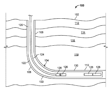
sized to fit from the wellbore entry through the substantially vertical, the
transition, and
the substantially horizontal portions of the wellbore, and into the storage
area, the
storage container including an inner cavity sized enclose hazardous material;
and a seal
1
Date Recue/Date Received 2023-05-31
positioned in the wellbore, the seal isolating the storage portion of the
wellbore from the
entry of the wellbore.
[0004] In an aspect combinable with the general implementation, the
storage
area is formed below the shale formation and is vertically isolated from the
subterranean
zone that includes mobile water by the shale formation.
[0005] In another aspect combinable with any of the previous
aspects, the
storage area is formed within the shale formation, and is vertically isolated
from the
subterranean zone that includes mobile water by at least a portion of the
shale formation.
[0006] In another aspect combinable with any of the previous
aspects, the shale
to formation includes a permeability of less than about 0.001 millidarcys.
[0007] In another aspect combinable with any of the previous
aspects, the shale
foiniation includes a brittleness of less than about 10 MPa, where brittleness
includes a
ratio of compressive stress of the shale formation to tensile strength of the
shale
formation.
[0008] In another aspect combinable with any of the previous aspects, the
shale
formation includes a thickness proximate the storage area of at least about
100 feet.
[0009] In another aspect combinable with any of the previous
aspects, the shale
formation includes a thickness proximate the storage area that inhibits
diffusion of the
hazardous material that escapes the storage container through the shale
foimation for an
amount of time that is based on a half-life of the hazardous material.
[0010] In another aspect combinable with any of the previous
aspects, the shale
formation includes about 20 to 30% weight by volume of clay or organic matter.
[0011] In another aspect combinable with any of the previous
aspects, the
hazardous material includes spent nuclear fuel.
[0012] Another aspect combinable with any of the previous aspects further
includes at least one casing assembly that extends from at or proximate the
terranean
surface, through the wellbore, and into the storage area.
[0013] In another aspect combinable with any of the previous
aspects, the
storage container includes a connecting portion configured to couple to at
least one of a
downhole tool string or another storage container.
[0014] In another general implementation, a method for storing
hazardous
material includes moving a storage container through an entry of a wellbore
that extends
into a terranean surface, the entry at least proximate the terranean surface,
the storage
2
Date Recue/Date Received 2023-05-31
container including an inner cavity sized enclose hazardous material; moving
the storage
container through the wellbore that includes a substantially vertical portion,
a transition
portion, and a substantially horizontal portion, the storage container sized
to fit from the
wellbore entry through the substantially vertical, the transition, and the
substantially
horizontal portions of the wellbore; moving the storage container into a
storage area that
is coupled to the substantially horizontal portion of the well bore, the
storage area located
within or below a shale formation and vertically isolated, by the shale
formation, from
a subterranean zone that includes mobile water; and fonning a seal in the
wellbore that
isolates the storage portion of the wellbore from the entry of the wellbore.
[0015] In an aspect combinable with the general implementation, the storage
area is formed below the shale formation and is vertically isolated from the
subterranean
zone that includes mobile water by the shale formation.
[0016] In another aspect combinable with any of the previous
aspects, the
storage area is formed within the shale fonnation.
[0017] In another aspect combinable with any of the previous aspects, the
shale
formation is geologically formed below an impermeable formation that is formed
between the shale formation and the subterranean zone that includes mobile
water.
[0018] In another aspect combinable with any of the previous
aspects, the shale
formation includes geological properties including two or more of: a
penneability of
less than about 0.001 millidarcys; a brittleness of less than about 10 MPa,
where
brittleness includes a ratio of compressive stress of the shale formation to
tensile strength
of the shale formation; a thickness proximate the storage area of at least
about 100 feet;
or about 20 to 30% weight by volume of organic material or clay.
[0019] In another aspect combinable with any of the previous
aspects, the
hazardous material includes spent nuclear fuel.
[0020] In another aspect combinable with any of the previous
aspects, the
wellbore further includes at least one casing that extends from at or
proximate the
terranean surface, through the wellbore, and into the storage area.
[0021] Another aspect combinable with any of the previous aspects
further
includes prior to moving the storage container through the entry of the
wellbore that
extends into the terranean surface, forming the wellbore from the terranean
surface to
the shale formation.
3
Date Recue/Date Received 2023-05-31
[0022] Another aspect combinable with any of the previous aspects
further
includes installing a casing in the wellbore that extends from at or proximate
the
terranean surface, through the wellbore, and into the storage area.
[0023] Another aspect combinable with any of the previous aspects
further
includes cementing the casing to the wellbore.
[0024] Another aspect combinable with any of the previous aspects
further
includes, subsequent to forming the wellbore, producing hydrocarbon fluid from
the
shale formation, through the wellbore, and to the terranean surface.
[0025] Another aspect combinable with any of the previous aspects
further
includes removing the seal from the wellbore; and retrieving the storage
container from
the storage area to the terranean surface.
[0026] Another aspect combinable with any of the previous aspects
further
includes monitoring at least one variable associated with the storage
container from a
sensor positioned proximate the storage area; and recording the monitored
variable at
the terranean surface.
[0027] In another aspect combinable with any of the previous
aspects, the
monitored variable includes at least one of radiation level, temperature,
pressure,
presence of oxygen, presence of water vapor, presence of liquid water,
acidity, or
seismic activity.
[0028] Another aspect combinable with any of the previous aspects further
includes, based on the monitored variable exceeding a threshold value:
removing the
seal from the wellbore; and retrieving the storage container from the storage
area to the
terranean surface.
[0029] In another general implementation, a spent nuclear fuel
storage system
includes a directional wellbore formed from a terranean surface, through a
first
subterranean layer, and into a second subterranean layer deeper than the first
subterranean layer, the first subterranean layer including a rock foimation
that includes
a source of mobile water, the second subterranean layer including a shale
formation that
fluidly isolates a portion of the directional wellbore formed within the shale
formation
from the first subterranean layer; a container configured to be moved through
the
directional wellbore into the portion of the directional wellbore formed
within the shale
formation, the container including a volume enclosed by a housing configured
to store
a plurality of spent nuclear fuel pellets; and a plug set in the directional
wellbore between
4
Date Recue/Date Received 2023-05-31
the portion of the directional wellbore formed within the shale formation and
the
terranean surface.
[0030] In an aspect combinable with the general implementation, the
directional
wellbore is formed through a third subterranean layer between the first and
second
subterranean layers, the third subterranean layer including a substantially
impermeable
rock formation .
[0031] In another aspect combinable with any of the previous
aspects, the
impemreable rock formation is more brittle than the shale formation.
[0032] In another aspect combinable with any of the previous
aspects, the
impermeable rock formation is less permeable than the shale formation.
[0033] Another aspect combinable with any of the previous aspects
further
includes a monitoring system, including a monitoring control system
communicably
coupled to one or more systems positioned proximate the container.
[0034] Another aspect combinable with any of the previous aspects
further
includes a tubular liner constructed in the directional wellbore and sealed
against a wall
of the directional wellbore.
[0035] The present disclosure also describes additional
implementations of a
hazardous material storage bank. For example, implementations of systems and
method
for storing a hazardous material include a wellbore formed from a terranean
surface to
a subterranean zone that includes shale, the wellbore including a
substantially vertical
portion, a radius portion, and a substantially non-vertical portion; a storage
container
positioned in the substantially non-vertical portion of the wellbore and
including a
volume sized to encapsulate a hazardous material that is isolated from a
source of mobile
water based upon proximity of the storage container in the shale; and a seal
positioned
in the wellbore between the storage container and an inlet of the wellbore at
the terranean
surface, the seal configured to fluidly isolate at least a portion of the
substantially non-
vertical portion from at least a portion of the substantially vertical
portion.
[0036] As another example, implementations of systems and method for
storing
a hazardous material include a wellbore formed from a terranean surface to a
subterranean zone, the wellbore including a substantially vertical portion, a
radius
portion, and a substantially non-vertical portion, the subterranean zone
including a
geologic formation defined by two or more of the following characteristics: a
permeability of less than about 0.001 millidarcys, a brittleness of less than
about 10
5
Date Recue/Date Received 2023-05-31
MPa, where brittleness includes a ratio of compressive stress of the shale
formation to
tensile strength of the shale formation, a thickness of typically about 100
feet, and about
20 to 30% weight by volume of organic material or clay; a storage container
positioned
in the substantially non-vertical portion of the wellbore and including a
volume sized to
encapsulate a hazardous material; and a seal positioned in the wellbore
between the
storage container and an inlet of the wellbore at the terranean surface.
[0037] As another example, implementations of systems and method for
banking a hazardous material, such as a spent nuclear fuel material, include
forming a
wellbore from a terranean surface to a subterranean zone that includes shale,
the
wellbore including a substantially vertical portion, a radius portion, and a
substantially
non-vertical portion; and pumping a hardenable slurry into the substantially
non-vertical
portion of the wellbore, the hardenable slurry including a mixture of a
hardenable
material (e.g., cement, resin, polymer, concrete, grout) and a spent nuclear
fuel material.
[0038] Implementations of a hazardous material storage bank
according to the
present disclosure may include one or more of the following features. For
example, a
hazardous material storage bank according to the present disclosure may allow
for
multiple levels of containment of hazardous material within a storage bank
located
thousands of feet underground, decoupled from any nearby mobile water. A
hazardous
material storage bank according to the present disclosure may also use proven
techniques (e.g., drilling) to create or form a storage area for the hazardous
material, in
a subterranean zone proven to have fluidly sealed hydrocarbons therein for
millions of
years. As another example, a hazardous material storage bank according to the
present
disclosure may provide long-term (e.g., thousands of years) storage for
hazardous
material (e.g., radioactive waste) in a shale formation that has geologic
properties
suitable for such storage, including low permeability, thickness, and
ductility, among
others. In addition, a greater volume of hazardous material may be stored at
low cost
¨ relative to conventional storage techniques ¨ due in part to directional
drilling
techniques that facilitate long horizontal boreholes, often exceeding a mile
in length. In
addition, rock formations that have geologic properties suitable for such
storage may be
found in close proximity to sites at which hazardous material may be found or
generated,
thereby reducing dangers associated with transporting such hazardous material.
[0039] Implementations of a hazardous material storage bank
according to the
present disclosure may also include one or more of the following features.
Large storage
6
Date Recue/Date Received 2023-05-31
volumes, in turn, allow for the storage of hazardous materials to be emplaced
without a
need for complex prior treatment, such as concentration or transfer to
different forms or
containers. As a further example, in the case of nuclear waste material from a
reactor
for instance, the waste can be kept in its original pellets, unmodified, or in
its original
fuel rods, or in its original fuel assemblies, which contain dozens of fuel
rods. In another
aspect, the hazardous material may be kept in an original holder but a cement
or other
material is injected into the holder to fill the gaps between the hazardous
materials and
the structure. For example, if the hazardous material is stored in fuel rods
which are, in
turn, stored in fuel assemblies, then the spaces between the rods (typically
filled with
water when inside a nuclear reactor) could be filled with cement or other
material to
provide yet an additional layer of isolation from the outside world. As yet a
further
example, secure and low cost storage of hazardous material is facilitated
while still
permitting retrieval of such material if circumstances deem it advantageous to
recover
the stored materials.
[0040] The details of one or more implementations of the subject matter
described in this disclosure are set forth in the accompanying drawings and
the
description below. Other features, aspects, and advantages of the subject
matter will
become apparent from the description and the drawings.
7
Date Recue/Date Received 2023-05-31
BRIEF DESCRIPTION OF THE DRAWINGS
[0041] FIGS. 1A-1C are schematic illustrations of example
implementations of
a hazardous material storage bank system during a deposit or retrieval
operation
according to the present disclosure.
[0042] FIGS. 2A-2E are schematic illustrations of example implementations
of
a hazardous material storage bank system during storage and monitoring
operations
according to the present disclosure.
[0043] FIGS. 3A-3B are schematic illustrations of other example
implementations of a hazardous material storage bank system according to the
present
disclosure.
[0044] FIGS. 4A-4C are schematic illustrations of an example
implementation
of a hazardous material container according to the present disclosure.
[0045] FIG. 5 is a schematic illustration of another example
implementation of
a hazardous material storage bank system according to the present disclosure.
[0046] FIGS. 6A-6C are flowcharts that illustrate example methods
associated
with storing hazardous material according to the present disclosure.
[0047] FIG. 7 is a schematic illustration of a controller or control
system for
monitoring a hazardous material storage bank system according to the present
disclosure.
DETAILED DESCRIPTION
[0048] The present disclosure describes a hazardous material storage
bank
system, which includes one or more wellbores formed into a subterranean zone
to
provide long-temi (e.g., tens, hundreds, or even thousands of years) storage
of hazardous
material (e.g., biological, chemical, nuclear, or otherwise) in one or more
underground
storage volumes storage containers. The subterranean zone includes multiple
subterranean layers having different geological formations and properties. The
storage
containers may be deposited in a particular subterranean layer based on one or
more
geologic properties of that layer, such as low permeability, sufficient
thickness, low
brittleness, and other properties. In some aspects, the particular
subterranean layer
comprises a shale formation, which forms an isolative seal between the storage
containers and another subterranean layer that comprises mobile water.
8
Date Recue/Date Received 2023-05-31
[0049] FIGS.
1A-1C are schematic illustrations of example implementations of
a hazardous material storage bank system, e.g., a subterranean location for
the long-teim
(e.g., tens, hundreds, or thousands of years or more) but retrievable safe and
secure
storage of hazardous material, during a deposit or retrieval operation
according to the
present disclosure. For example, turning to FIG. 1A, this figure illustrates
an example
hazardous material storage bank system 100 during a deposit (or retrieval, as
described
below) process, e.g., during deployment of one or more containers of hazardous
material
in a subterranean formation. As illustrated, the hazardous material storage
bank system
100 includes a wellbore 104 formed (e.g., drilled or otherwise) from a
terranean surface
102 and through multiple subterranean layers 112, 114, 116, and 118. Although
the
terranean surface 102 is illustrated as a land surface, terranean surface 102
may be a sub-
sea or other underwater surface, such as a lake or an ocean floor or other
surface under
a body of water. Thus, the present disclosure contemplates that the wellbore
104 may
be fonned under a body of water from a drilling location on or proximate the
body of
water.
[0050] The
illustrated wellbore 104 is a directional wellbore in this example of
hazardous material storage bank system 100. For instance, the wellbore 104
includes a
substantially vertical portion 106 coupled to a radiussed or curved portion
108, which in
turn is coupled to a substantially horizontal portion 110. As used in the
present
disclosure, "substantially" in the context of a wellbore orientation, refers
to wellbores
that may not be exactly vertical (e.g., exactly perpendicular to the terranean
surface 102)
or exactly horizontal (e.g., exactly parallel to the terranean surface 102).
In other words,
those of ordinary skill in the drill arts would recognize that vertical
wellbores often
undulate offset from a true vertical direction, that they might be drilled at
an angle that
deviates from true vertical, and horizontal wellbores often undulate offset
from a true
horizontal direction. Further, the substantially horizontal portion 110, in
some aspects,
may be a slant wellbore or other directional wellbore that is oriented between
exactly
vertical and exactly horizontal. Further, the substantially horizontal portion
110, in
some aspects, may be a slant wellbore or other directional well bore that is
oriented to
follow the slant of the formation. As illustrated in this example, the three
portions of
the wellbore 104 ____________________________________________________ the
vertical portion 106, the radiussed portion 108, and the
horizontal portion 110 ¨ form a continuous wellbore 104 that extends into the
Earth.
9
Date Recue/Date Received 2023-05-31
[0051] The illustrated wellbore 104 has a surface casing 120
positioned and set
around the wellbore 104 from the terranean surface 102 into a particular depth
in the
Earth. For example, the surface casing 120 may be a relatively large-diameter
tubular
member (or string of members) set (e.g., cemented) around the wellbore 104 in
a shallow
formation. As used herein, "tubular" may refer to a member that has a circular
cross-
section, elliptical cross-section, or other shaped cross-section. For example,
in this
implementation of the hazardous material storage bank system 100, the surface
casing
120 extends from the terranean surface through a surface layer 112. The
surface layer
112, in this example, is a geologic layer comprised of one or more layered
rock
to formations. In some aspects, the surface layer 112 in this example may
or may not
include freshwater aquifers, salt water or brine sources, or other sources of
mobile water
(e.g., water that moves through a geologic formation). In some aspects, the
surface
casing 112 may isolate the wellbore 104 from such mobile water, and may also
provide
a hanging location for other casing strings to be installed in the wellbore
104. Further,
although not shown, a conductor casing may be set above the surface casing 112
(e.g.,
between the surface casing 112 and the surface 102 and within the surface
layer 112) to
prevent drilling fluids from escaping into the surface layer 112.
[0052] As illustrated, a production casing 122 is positioned and set
within the
wellbore 104 downhole of the surface casing 120. Although temied a
"production"
casing, in this example, the casing 122 may or may not have been subject to
hydrocarbon
production operations. Thus, the casing 122 refers to and includes any form of
tubular
member that is set (e.g., cemented) in the wellbore 104 downhole of the
surface casing
120. In some examples of the hazardous material storage bank system 100, the
production casing 122 may begin at an end of the radiussed portion 108 and
extend
throughout the substantially horizontal portion 110. The casing 122 could also
extend
into the radiussed portion 108 and into the vertical portion 106.
[0053] As shown, cement 130 is positioned (e.g., pumped) around the
casings
120 and 122 in an annulus between the casings 120 and 122 and the wellbore
104. The
cement 130, for example, may secure the casings 120 and 122 (and any other
casings or
liners of the wellbore 104) through the subterranean layers under the
terranean surface
102. In some aspects, the cement 130 may be installed along the entire length
of the
casings (e.g., casings 120 and 122 and any other casings), or the cement 130
could be
used along certain portions of the casings if adequate for a particular
wellbore 102. The
Date Recue/Date Received 2023-05-31
cement 130 can also provide an additional layer of confinement for the
hazardous
material in containers 126.
[0054] The wellbore 104 and associated casings 120 and 122 may be
formed
with various example dimensions and at various example depths (e.g., true
vertical
depth, or TVD). For instance, a conductor casing (not shown) may extend down
to about
120 feet TVD, with a diameter of between about 28 in. and 60 in. The surface
casing
120 may extend down to about 2500 feet TVD, with a diameter of between about
22 in.
and 48 in. An intermediate casing (not shown) between the surface casing 120
and
production casing 122 may extend down to about 8000 feet TVD, with a diameter
of
between about 16 in. and 36 in. The production casing 122 may extend
substantially
horizontally (e.g., to case the substantially horizontal portion 110) with a
diameter of
between about 11 in. and 22 in. The foregoing dimensions are merely provided
as
examples and other dimensions (e.g., diameters, TVDs, lengths) are
contemplated by
the present disclosure. For example, diameters and TVDs may depend on the
particular
geological composition of one or more of the multiple subterranean layers (112-
118),
particular drilling techniques, as well as a size, shape, or design of a
hazardous material
container 126 that contains hazardous material to be deposited in the
hazardous material
storage bank system 100. In some alternative examples, the production casing
122 (or
other casing in the wellbore 104) could be circular in cross-section,
elliptical in cross-
section, or some other shape.
[0055] As illustrated, the wellbore 104 extends through subterranean
layers 112,
114, and 116, and lands in subterranean layer 118. As discussed above, the
surface layer
112 may or may not include mobile water. Subterranean layer 114, which is
below the
surface layer 112, in this example, is a mobile water layer 114. For instance,
mobile
water layer 114 may include one or more sources of mobile water, such as
freshwater
aquifers, salt water or brine, or other source of mobile water. In this
example of
hazardous material storage bank system 100, mobile water may be water that
moves
through a subterranean layer based on a pressure differential across all or a
part of the
subterranean layer. For example, the mobile water layer 114 may be a permeable
geologic formation in which water freely moves (e.g., due to pressure
differences or
otherwise) within the layer 114. In some aspects, the mobile water layer 114
may be a
primary source of human-consumable water in a particular geographic area.
Examples
11
Date Recue/Date Received 2023-05-31
of rock formations of which the mobile water layer 114 may be composed include
porous sandstones and limestones, among other formations.
[0056] Below the mobile water layer 114, in this example
implementation of
hazardous material storage bank system 100, is an impermeable layer 116. The
impermeable layer 116, in this example, may not allow mobile water to pass
through.
Thus, relative to the mobile water layer 114, the impermeable layer 116 may
have low
permeability, e.g., on the order of nariodarcy permeability. Additionally, in
this
example, the impermeable layer 116 may be a relatively non-ductile (i.e.,
brittle)
geologic formation. One measure of non-ductility is brittleness, which is the
ratio of
compressive stress to tensile strength. In some examples, the brittleness of
the
impermeable layer 116 may be between about 20 MPa and 40 MPa.
[0057] As shown in this example, the impermeable layer 116 is
shallower (e.g.,
closer to the terranean surface 102) than the storage layer 119. In this
example rock
formations of which the impermeable layer 116 may be composed include, for
example,
certain kinds of sandstone, mudstone, clay, and slate that exhibit
permeability and
brittleness properties as described above. In alternative examples, the
impermeable
layer 116 may be deeper (e.g., further from the terranean surface 102) than
the storage
layer 119. In such alternative examples, the impermeable layer 116 may be
composed
of an igneous rock, such as granite.
[0058] Below the impermeable layer 116 is a storage layer 118. The storage
layer 118, in this example, may be chosen as the landing for the substantially
horizontal
portion 110, which stores the hazardous material, for several reasons.
Relative to the
impermeable layer 116 or other layers, the storage layer 118 may be thick,
e.g., between
about 100 and 200 feet of total vertical thickness. Thickness of the storage
layer 118
may allow for easier landing and directional drilling, thereby allowing the
substantially
horizontal portion 110 to be readily emplaced within the storage layer 118
during
constructions (e.g., drilling). If formed through an approximate horizontal
center of the
storage layer 118, the substantially horizontal portion 110 may be surrounded
by about
50 to 100 feet of the geologic formation that comprises the storage layer 118.
Further,
the storage layer 118 may also have no mobile water, e.g., due to a very low
permeability
of the layer 118 (e.g., on the order of milli- or nanodarcys). In addition,
the storage layer
118 may have sufficient ductility, such that a brittleness of the rock
formation that
comprises the layer 118 is between about 3 MPa and 10 MPa. Examples of rock
12
Date Recue/Date Received 2023-05-31
formations of which the storage layer 118 may be composed include: shale and
anhydrite. Further, in some aspects, hazardous material may be stored below
the storage
layer, even in a permeable folination such as sandstone or limestone, if the
storage layer
is of sufficient geologic properties to isolate the permeable layer from the
mobile water
layer 114.
[0059] In some examples implementations of the hazardous material
storage
bank system 100, the storage layer 118 is composed of shale. Shale, in some
examples,
may have properties that fit within those described above for the storage
layer 118. For
example, shale formations may be suitable for a long-term confinement of
hazardous
to material (e.g., in the hazardous material containers 126), and for their
isolation from
mobile water layer 114 (e.g., aquifers) and the terranean surface 102. Shale
folinations
may be found relatively deep in the Earth, typically 3000 feet or greater, and
placed in
isolation below any fresh water aquifers.
[0060] Shale formations, for instance, may include geologic
properties that
enhance the long-term (e.g., thousands of years) isolation of material. Such
properties,
for instance, have been illustrated through the long term storage (e.g., tens
of millions
of years) of hydrocarbon fluids (e.g., gas, liquid, mixed phase fluid) without
escape of
such fluids into surrounding layers (e.g., mobile water layer 114). Indeed,
shale has
been shown to hold natural gas for millions of years or more, giving it a
proven
capability for long-term storage of hazardous material. Example shale
formations (e.g.,
Marcellus, Eagle Ford, Barnett, and otherwise) has stratification that
contains many
redundant sealing layers that have been effective in preventing movement of
water, oil,
and gas for millions of years, lacks mobile water, and can be expected (e.g.,
based on
geological considerations) to seal hazardous material (e.g., fluids or solids)
for
thousands of years after deposit.
[00611 Shale formations may also be at a suitable depth, e.g.,
between 3000 and
12,000 feet TVD. Such depths are typically below ground water aquifer (e.g.,
surface
layer 112 and/or mobile water layer 114). Further, the presence of soluble
elements in
shale, including salt, and the absence of these same elements in aquifer
layers,
demonstrates a fluid isolation between shale and the aquifer layers.
[0062] Another particular quality of shale that may advantageously
lend itself to
hazardous material storage is its clay content, which, in some aspects,
provides a
measure of ductility greater than that found in other, impermeable rock
folinations (e.g.,
13
Date Recue/Date Received 2023-05-31
impermeable layer 116). For example, shale may be stratified, made up of
thinly
alternating layers of clays (e.g., between about 20-30% clay by volume) and
other
minerals. Such a composition may make shale less brittle and, thus less
susceptible to
fracturing (e.g., naturally or otherwise) as compared to rock formations in
the
impermeable layer (e.g., granite or otherwise). For example, rock formations
in the
impermeable layer 116 may have suitable permeability for the long term storage
of
hazardous material, but are too brittle and commonly are fractured. Thus, such
formations may not have sufficient sealing qualities (as evidenced through
their geologic
properties) for the long term storage of hazardous material.
in [0063] The present disclosure contemplates that there may be many
other layers
between or among the illustrated subterranean layers 112, 114, 116, and 118.
For
example, there may be repeating patterns (e.g., vertically), of one or more of
the mobile
water layer 114, impermeable layer 116, and storage layer 118. Further, in
some
instances, the storage layer 118 may be directly adjacent (e.g., vertically)
the mobile
water layer 114, i.e., without an intervening impermeable layer 116.
[0064] FIG. 1A illustrates an example of a deposit operation of
hazardous
material in the substantially horizontal portion 110 of the wellbore 104. For
example,
as shown, a work string 124 (e.g., tubing, coiled tubing, wireline, or
otherwise) may be
extended into the cased wellbore 104 to place one or more (three shown but
there may
be more or less) hazardous material containers 126 into long term, but in some
aspects,
retrievable, storage in the portion 110. For example, in the implementation
shown in
FIG. 1A, the work string 124 may include a downhole tool 128 that couples to
the
container 126, and with each trip into the wellbore 104, the downhole tool 128
may
deposit a particular hazardous material container 126 in the substantially
horizontal
portion 110.
[0065] The downhole tool 128 may couple to the container 126 by, in
some
aspects, a threaded connection. In alternative aspects, the downhole tool 128
may couple
to the container 126 with an interlocking latch, such that rotation of the
downhole tool
128 may latch to (or unlatch from) the container 126. In alternative aspects,
the
downhole tool 124 may include one or more magnets (e.g., rare Earth magnets,
electromagnets, a combination thereof, or otherwise) which attractingly couple
to the
container 126. In some examples, the container 126 may also include one or
more
magnets (e.g., rare Earth magnets, electromagnets, a combination thereof, or
otherwise)
14
Date Recue/Date Received 2023-05-31
of an opposite polarity as the magnets on the downhole tool 124. In some
examples, the
container 126 may be made from or include a ferrous or other material
attractable to the
magnets of the downhole tool 124.
[0066] As another example, each container 126 may be positioned
within the
wellbore 104 by a wellbore tractor (e.g., on a wireline or otherwise), which
may push or
pull the container into the substantially horizontal portion 110 through
motorized (e.g.,
electric) motion. As yet another example, each container 126 may include or be
mounted to rollers (e.g., wheels), so that the downhole tool 124 may push the
container
126 into the cased wellbore 104.
[0067] In some example implementations, the container 126, one or more of
the
wellbore casings 120 and 122, or both, may be coated with a friction-reducing
coating
prior to the deposit operation. For example, by applying a coating (e.g.,
petroleum-
based product, resin, ceramic, or otherwise) to the container 126 and/or
wellbore
casings, the container 126 may be more easily moved through the cased wellbore
104
into the substantially horizontal portion 100. In some aspects, only a portion
of the
wellbore casings may be coated. For example, in some aspects, the
substantially vertical
portion 106 may not be coated, but the radiussed portion 108 or the
substantially
horizontal portion 110, or both, may be coated to facilitate easier deposit
and retrieval
of the container 126.
[0068] FIG. lA also illustrates an example of a retrieval operation of
hazardous
material in the substantially horizontal portion 110 of the wellbore 104. A
retrieval
operation may be the opposite of a deposit operation, such that the downhole
tool 124
(e.g., a fishing tool) may be run into the wellbore 104, coupled to the last-
deposited
container 126 (e.g., threadingly, latched, by magnet, or otherwise), and pull
the container
126 to the terranean surface 102. Multiple retrieval trips may be made by the
downhole
tool 124 in order to retrieve multiple containers from the substantially
horizontal portion
110 of the wellbore 104.
[0069] Each container 126 may enclose hazardous material. Such
hazardous
material, in some examples, may be biological or chemical waste or other
biological or
chemical hazardous material. In some examples, the hazardous material may
include
nuclear material, such as spent nuclear fuel recovered from a nuclear reactor
(e.g.,
commercial power or test reactor) or military nuclear material. For example, a
gigawatt
nuclear plant may produce 30 tons of spent nuclear fuel per year. The density
of that
Date Recue/Date Received 2023-05-31
fuel is typically close to 10 (10 gm/cm3 = 10 kg/liter), so that the volume
for a year of
nuclear waste is about 3 m3. Spent nuclear fuel, in the form of nuclear fuel
pellets, may
be taken from the reactor and not modified. Nuclear fuel pellets are solid,
and emit very
little gas other than short-lived tritium (13 year half-life).
[0070] In some aspects, the storage layer 118 should be able to contain any
radioactive output (e.g., gases) within the layer 118, even if such output
escapes the
containers 126. For example, the storage layer 118 may be selected based on
diffusion
times of radioactive output through the layer 118. For example, a minimum
diffusion
time of radioactive output escaping the storage layer 118 may be set at, for
example,
fifty times a half-life for any particular component of the nuclear fuel
pellets. Fifty half-
lives as a minimum diffusion time would reduce an amount of radioactive output
by a
factor of 1 x 10-15. As another example, setting a minimum diffusion time to
thirty half-
lives would reduce an amount of radioactive output by a factor of one billion.
[0071] For example, plutonium-239 is often considered a dangerous
waste
product in spent nuclear fuel because of its long half-life of 24,100 years.
For this
isotope, 50 half-lives would be 1.2 million years. Plutonium-239 has low
solubility in
water, is not volatile, and as a solid is not capable of diffusion through a
matrix of the
rock formation that comprises the illustrated storage layer 118 (e.g., shale
or other
formation). The storage layer 118, for example comprised of shale, may offer
the
capability to have such isolation times (e.g., millions of years) as shown by
the
geological history of containing gaseous hydrocarbons (e.g., methane and
otherwise) for
several million years. In contrast, in conventional nuclear material storage
methods,
there was a danger that some plutonium might dissolve in a layer that
comprised mobile
ground water upon confinement escape.
[0072] Turning to FIG. 1B, an alternative deposit operation is illustrated.
In this
example deposit operation, a fluid 132 (e.g., liquid or gas) may be circulated
through the
wellbore 104 to fluidly push the containers 126 into the substantially
horizontal wellbore
portion 110. In some example, each container 126 may be fluidly pushed
separately. In
alternative aspects, two or more containers 126 may be fluidly pushed,
simultaneously,
through the wellbore 104 for deposit into the substantially horizontal portion
110. The
fluid 132 can be, in some cases, water. Other examples include a drilling mud
or drilling
foam. In some examples, a gas may be used to push the containers 126 into the
wellbore,
such as air, argon, or nitrogen.
16
Date Recue/Date Received 2023-05-31
[0073] In some aspects, the choice of fluid 132 may depend at least
in part on a
viscosity of the fluid 132. For example, a fluid 132 may be chosen with enough
viscosity
to impede the drop of the container 126 into the substantially vertical
portion 106. This
resistance or impedance may provide a safety factor against a sudden drop of
the
container 126. The fluid 132 may also provide lubrication to reduce a sliding
friction
between the container 126 and the casings 120 and 122. The container 126 can
be
conveyed within a casing filled with a liquid of controlled viscosity,
density, and
lubricant qualities. The fluid-filled annulus between the inner diameter of
the casings
120 and 122 and the outer diameter of the conveyed container 126 represents an
opening
designed to dampen any high rate of container motion, providing automatic
passive
protection in an unlikely decoupling of the conveyed container 126.
[0074] In some aspects, other techniques may be employed to
facilitate deposit
of the container 126 into the substantially horizontal portion 110. For
example, one or
more of the installed casings (e.g., casings 120 and 122) may have rails to
guide the
storage container 126 into the wellbore 102 while reducing friction between
the casings
and the container 126. The storage container 126 and the casings (or the
rails) may be
made of materials that slide easily against one another. The casings may have
a surface
that is easily lubricated, or one that is self-lubricating when subjected to
the weight of
the storage container 126.
[0075] The fluid 132 may also be used for retrieval of the container 126.
For
example, in an example retrieval operation, a volume within the casings 120
and 122
may be filled with a compressed gas (e.g., air, nitrogen, argon, or
otherwise). As the
pressure increases at an end of the substantially horizontal portion 110, the
containers
126 may be pushed toward the radiussed portion 108, and subsequently through
the
substantially vertical portion 106 to the tenanean surface.
[0076] Turning to FIG. 1C, another alternative deposit operation is
illustrated.
In this example deposit operation, the fluid 132 (e.g., liquid or gas) may be
circulated
through a tubular fluid control casing 134 to fluidly push the containers 126
into the
substantially horizontal wellbore portion 110. The fluid 132 may circulate
through an
end of the substantially horizontal portion 110 in the fluid control casing
134 and
recirculate back to the terranean surface 102 in an annulus between the fluid
control
casing 134 and the casings 122 and 120. In some examples, each container 126
may be
fluidly pushed separately. The annulus between the fluid control casing 134
and the
17
Date Recue/Date Received 2023-05-31
casings 120 and 122 may be filled with a fluid or compressed gas to reverse
the flow of
fluid 132, e.g., in order to push the containers 126 back towards the
terranean surface
102. In alternative aspects, two or more containers 126 may be fluidly pushed,
simultaneously, through the wellbore 104 for deposit into the substantially
horizontal
portion 110. The fluid control casing 134 could be similar or identical to the
production
casing 122. For that case, a separate tubular member could be enclosed in the
wellbore
102 or within the production casing 122 to provide a return path for the fluid
132.
[0077] In some aspects, the wellbore 104 may be formed for the
primary purpose
of long-term storage of hazardous materials. In alternative aspects, the
wellbore 104
may have been previously formed for the primary purpose of hydrocarbon
production
(e.g., oil, gas). For example, storage layer 118 may be a hydrocarbon bearing
formation
from which hydrocarbons were produced into the wellbore 104 and to the
terranean
surface 102. In some aspects, the storage layer 118 may have been
hydraulically
fractured prior to hydrocarbon production. Further in some aspects, the
production
casing 122 may have been perforated prior to hydraulic fracturing. In such
aspects, the
production casing 122 may be patched (e.g., cemented) to repair any holes made
from
the perforating process prior to a deposit operation of hazardous material. In
addition,
any cracks or openings in the cement between the casing and the drill hole can
also be
filled at that time.
[0078] For example, in the case of spent nuclear fuel as a hazardous
material,
the wellbore may be formed at a particular location, e.g., near a nuclear
power plant, as
a new wellbore provided that the location also includes an appropriate storage
layer 118,
such as a shale formation. Alternatively, an existing well that has already
produced
shale gas, or one that was abandoned as "dry," (e.g., with sufficiently low
organics that
the gas in place is too low for commercial development), may be selected as
the wellbore
104. In some aspects, prior hydraulic fracturing of the storage layer 118
through the
wellbore 104 may make little difference in the hazardous material storage
capability of
the wellbore 104. But such a prior activity may also confirm the ability of
the storage
layer 118 to store gases and other fluids for millions of years. If,
therefore, the hazardous
material or output of the hazardous material (e.g., radioactive gasses or
otherwise) were
to escape from the container 126 and enter the fractured formation of the
storage layer
118, such fractures may allow that material to spread relatively rapidly over
a distance
comparable in size to that of the fractures. In some aspects, the wellbore 102
may have
18
Date Recue/Date Received 2023-05-31
been drilled for a production of hydrocarbons, but production of such
hydrocarbons had
failed, e.g., because the storage layer 118 comprised a rock formation (e.g.,
shale or
otherwise) that was too ductile and difficult to fracture for production, but
was
advantageously ductile for the long-term storage of hazardous material.
[0079] FIGS. 2A-2E are schematic illustrations of example implementations
of
a hazardous material storage bank system during storage and monitoring
operations
according to the present disclosure. For example, FIG. 2A illustrates the
hazardous
material storage bank system 100 in a long twit storage operation. One or more
hazardous material containers 126 are positioned in the substantially
horizontal portion
110 of the wellbore 104. A seal 134 is placed in the wellbore 104 between the
location
of the containers 126 in the substantially horizontal portion 110 and an
opening of the
substantially vertical portion 106 at the terranean surface 102 (e.g., a well
head). In this
example, the seal 134 is placed at an uphole end of the substantially vertical
portion 108.
Alternatively, the seal 134 may be positioned at another location within the
substantially
vertical portion 106, in the radiussed portion 108, or even within the
substantially
horizontal portion 110 uphole of the containers 126. In some aspects, the seal
134 may
be placed at least deeper than any source of mobile water, such as the mobile
water layer
114, within the wellbore 104. In some aspects, the seal 134 may be formed
substantially
along an entire length of the substantially vertical portion 106.
[0080] As illustrated, the seal 134 fluidly isolates the volume of the
substantially
horizontal portion 110 that stores the containers 126 from the opening of the
substantially vertical portion 106 at the terranean surface 102. Thus, any
hazardous
material (e.g., radioactive material) that does escape the containers 126 may
be sealed
(e.g., such that liquid, gas, or solid hazardous material) does not escape the
wellbore
104. The seal 134, in some aspects, may be a cement plug or other plug, that
is
positioned or formed in the wellbore 104. As another example, the seal 134 may
be
formed from one or more inflatable or otherwise expandable packers positioned
in the
wellbore 104.
[0081] Prior to a retrieval operation (e.g., as discussed with
reference to FIGS.
1A-1B), the seal 134 may be removed. For example, in the case of a cement or
other
permanently set seal 134, the seal 134 may be drilled through or otherwise
milled away.
In the case of semi-permanent or removable seals, such as packers, the seal
134 may be
removed from the wellbore 104 through a conventional process as is known.
19
Date Recue/Date Received 2023-05-31
[0082] FIG. 2B illustrates an example monitoring operation during
long term
storage of the containers 126. For example, in some aspects, it may be
advantageous or
required to monitor one or more variables during long term storage of the
hazardous
material in the containers 126. In this example of FIG. 2B, the monitoring
system
includes one or more sensors 138 placed in the wellbore 104 (e.g., within the
substantially horizontal portion 110) and communicably coupled to a monitoring
control
system 146 through a cable 136 (e.g., electrical, optical, hydraulic, or
otherwise).
Although illustrated as within wellbore 102 (e.g., inside of the casings), the
sensors 138
may be placed outside of the casings, or even built into the casings before
the casings
to are installed in the wellbore 102. Sensors 138 could also be placed
outside the casing
(e.g., casings 120 and/or 122), or outside the fluid control casing 134.
[0083] As shown, the sensors 138 may monitor one or more variables,
such as,
for example, radiation levels, temperature, pressure, presence of oxygen, a
presence of
water vapor, a presence of liquid water, acidity, seismic activity, or a
combination
thereof. Data values related to such variables may be transmitted along the
cable 136 to
the monitoring control system 146. The monitoring control system 146, in turn,
may
record the data, determine trends in the data (e.g., rise of temperature, rise
of radioactive
levels), send data to other monitoring locations, such as national security or
environmental center locations, and may further automatically recommend
actions (e.g.,
retrieval of the containers 126) based on such data or trends. For example, a
rise in
temperature or radioactive level in the wellbore 104 above a particular
threshold level
may trigger a retrieval recommendation, e.g., to ensure that the containers
126 are not
leaking radioactive material. In some aspects, there may be a one-to-one ratio
of sensors
138 to containers 126. In alternative aspects, there may be multiple sensors
138 per
container 126, or there may be fewer.
[0084] FIG. 2C shows another example monitoring operation during
long term
storage of the containers 126. In this example, sensors 138 are positioned
within a
secondary horizontal wellbore 140 that is formed separately from the
substantially
vertical portion 106. The secondary horizontal wellbore 140 may be an uncased
wellbore, through which the cable 136 may extend between the monitoring
control
system 146 and the sensors 138. In this example, the secondary horizontal
wellbore 140
is foimed above the substantially horizontal portion 110 but within the
storage layer 118.
Thus, the sensors 138 may record data (e.g., radiation levels, temperature,
acidity,
Date Recue/Date Received 2023-05-31
seismic activity) of the storage layer 118. In alternative aspects, the
secondary
horizontal wellbore 140 may be formed below the storage layer 118, above the
storage
layer in the impermeable layer 116, or in other layers. Further, although FIG.
2C shows
the secondary horizontal wellbore 140 formed from the same substantially
vertical
portion 106 as the substantially horizontal portion 110, the secondary
horizontal
wellbore 140 may be formed from a separate vertical wellbore and radiussed
wellbore.
[00851 FIG. 2D shows another example monitoring operation during
long term
storage of the containers 126. In this example, sensors 138 are positioned
within a
secondary vertical wellbore 142 that is formed separately from the wellbore
104. The
tor) secondary vertical wellbore 142 may be a cased or an uncased wellbore,
through which
the cable 136 may extend between the monitoring control system 146 and the
sensors
1388. In this example, the secondary vertical wellbore 142 bottoms out above
the
substantially horizontal portion 110 but within the storage layer 118. Thus,
the sensors
1388 may record data (e.g., radiation levels, temperature, acidity, seismic
activity) of
the storage layer 118. In alternative aspects, the secondary vertical wellbore
140 may
bottom out below the storage layer 118, above the storage layer in the
impermeable layer
116, or in other layers. Further, although shown placed in the secondary
vertical
wellbore 142 at a level adjacent the storage layer 118, sensors 138 may be
placed
anywhere within the secondary vertical wellbore 142. Alternatively, the
secondary
vertical wellbore 142 may, in some aspects, be constructed prior to wellbore
102,
thereby permitting monitoring by installed sensors 138 during construction of
the
wellbore 102. Also, the monitoring borehole 142 could be sealed to prevent the
possibility that material that leaks into borehole 142 would have a path to
the terranean
surface 102.
[0086] FIG. 2E shows another example monitoring operation during long term
storage of the containers 126. In this example, sensors 138 are positioned
within a
secondary directional wellbore 144 that is formed separately from the wellbore
104. The
secondary directional wellbore 144 may be an uncased wellbore, through which
the
cable 136 may extend between the monitoring control system 146 and the sensors
138.
In this example, the secondary directional wellbore 144 lands adjacent the
substantially
horizontal portion 110 and within the storage layer 118. Thus, the sensors 138
may
record data (e.g., radiation levels, temperature, acidity, seismic activity)
of the storage
layer 118. In alternative aspects, the secondary directional wellbore 144 may
land below
21
Date Recue/Date Received 2023-05-31
the storage layer 118, above the storage layer in the impermeable layer 116,
or in other
layers. Further, although shown placed in the secondary directional wellbore
144 at a
level adjacent the storage layer 118, sensors 138 may be placed anywhere
within the
secondary directional wellbore 144. In some aspects, the secondary directional
wellbore
144 may be used for retrieval of the containers 126, for example, in case the
wellbore
104 is inaccessible.
[0087] FIG. 3A is a schematic illustration of another example
implementation
of a hazardous material storage bank system according to the present
disclosure. FIG.
3A illustrates an overhead schematic diagram of an hazardous material storage
bank
system 300 that illustrates an example configuration of wellbores that can be
formed or
used to store hazardous material, such as spent nuclear fuel, biological
material, or
chemical material. Hazardous material storage bank system 300 includes a
vertical
wellbore 302 (viewed from above here) with multiple horizontal wellbores 304
extending therefrom. In this example, four horizontal wellbores 304 may be
formed
from the single vertical wellbore 302.
[0088] The example hazardous material storage bank system 300 shows
a
storage bank that can provide long-term (e.g., millions of years) storage for
a volume of
hazardous material greater than, for example, the hazardous material storage
bank
system 100. For instance, each horizontal wellbore 304 may be substantially
similar to
the substantially horizontal portion 110 shown in FIG. 2A, which can store one
or more
containers 126 of hazardous material. Each horizontal wellbore 304 may be
formed in
the storage layer 118 or below the storage layer 118 to provide a sufficient
seal against
the diffusion of hazardous output in the event of a leak from the one or more
containers.
Thus, in the example of hazardous material storage bank system 300, hazardous
material
may be stored more efficiently, as only a single vertical wellbore 302 need be
formed to
account for multiple horizontal wells 304.
[0089] FIG. 3B is another schematic illustration of another example
implementation of a hazardous material storage bank system according to the
present
disclosure. FIG. 3B illustrates an overhead schematic diagram of an hazardous
material
storage bank system 350 that illustrates an example configuration of wellbores
that can
be formed or used to store hazardous material, such as spent nuclear fuel,
biological
material, or chemical material. In this example, the system 350 includes a
vertical
wellbore 352 with multiple lateral wellbores 354 formed from the vertical
wellbore 352.
22
Date Recue/Date Received 2023-05-31
The lateral wellbores 354, in this example, are substantially parallel to each
other in a
"pitchfork" pattern (or other pattern, such as an "F" pattern, crow's foot
pattern, or
otherwise). Each lateral wellbore 354 may be formed in the storage layer 118
or below
the storage layer 118 to provide a sufficient seal against the diffusion of
hazardous
output in the event of a leak from the one or more containers. In addition,
each lateral
wellbore 354 may be or include a storage area for containers 126.
[00901 FIGS. 4A-4C are schematic illustrations of an example
implementation
of a hazardous material container according to the present disclosure. FIGS.
4A-4C
illustrate isometric, vertical cross-section, and horizontal cross-section
views,
respectively, of a hazardous material container 400. In some aspects, the
hazardous
material container 400 may be similar to the illustrated container 126 and
usable in the
hazardous material storage bank system 100, the hazardous material storage
bank system
400, or other hazardous material storage bank system according to the present
disclosure. The hazardous material container 400 may be used to store chemical
hazardous material, biological hazardous material, nuclear hazardous material,
or
otherwise. For example, in the illustrated implementation, the hazardous
material
container 400 stores spent nuclear fuel in the form of spent nuclear fuel rods
406.
[00911 As illustrated, the hazardous material container 400 includes
a housing
402 (e.g., a crush-proof or crush resistant housing) that encloses a volume
404 to store
the hazardous material. In this example, the spent nuclear fuel rods 406 are
positioned
in the housing 402 prior to sealing of the hazardous material container 400.
Each spent
nuclear fuel rod 406 comprises multiple spent nuclear fuel pellets 408. For
example, the
spent nuclear fuel pellets 408 contain most of the radioisotopes (including
the tritium)
of the spent nuclear fuel removed from a nuclear reactor. To form the spent
nuclear fuel
rods 406, the fuel pellets 408 are surrounded by zirconium tubes, just as in
the reactor.
These tubes offer an additional level of containment. The tubes can be mounted
in the
original fuel assemblies, or removed from those assemblies for tighter packing
for the
spent nuclear fuel rods 406. The tubes are placed in sealed capsules to form
the rods
406, typically 15 feet long, with a diameter large enough to store a
substantial number
of fuel pellets 408, yet small enough to pennit placement in the housing 402.
[0092] In some aspects, the housing 402 (and other components of the
hazardous
material container 400) may be formed from metals or ceramics that, for
example, have
very high resistance to corrosion or radioactivity (e.g., zirconium or its
alloy zircaloy,
23
Date Recue/Date Received 2023-05-31
stainless steel, titanium, or other low corrosion materials). In addition, in
some aspects,
a storage area into which the container 400 is placed may be filled or
partially filled with
nitrogen, argon, or some other gas that reduces danger of corrosion to the
housing 402
and other components of the container 400.
[0093] Further, the dimensions of the housing 402 (and hazardous material
container 400, generally) may be designed to fit in a wellbore, such as the
wellbore 104.
Example dimensions of the housing 402 may include a length, L, of between 12
and 15
feet, and, in the case of a substantially square housing 402, side width, W,
of between 5
and 9 inches. The housing 402, in alternative aspects, may have a
substantially circular
to horizontal cross-section diameter of between about 7 and 13 in. In some
examples, the
hazardous material container 400 (and container 126) may be sized (e.g.,
length and
width/diameter) for efficient deposit and retrieval into and from the wellbore
104. For
example, the length, L, may be determined based on, e.g., the radius dimension
of the
radiussed portion 108, to ensure that the hazardous material container 400 may
be moved
through the radiussed portion 108 and into the substantially horizontal
portion 110. As
another example, the width, W, may be determined based on a diameter of one or
more
of the casings in the wellbore 104, such as the surface casing 120 and the
production
casing 122.
[0094] The illustrated hazardous material container 400 also
includes a
connector portion 410, which is shown on one end of the housing 402 but may be
formed
on both ends as well. In some aspects, the connector portion 410 may
facilitate coupling
of the hazardous material container 400 to a downhole tool (e.g., downhole
tool 128) to
permit deposit and retrieval of the hazardous material container 400 from
storage in a
wellbore. Further, the connector portion 410 may facilitate coupling of one
hazardous
material container 400 to another hazardous material container 400. The
connector
portion 410, in some aspects, may be a threaded connection. For example, a
connector
portion 410 on one end of the housing 402 may be a male threaded connection
while a
connector portion 410 on the opposite end of the housing 402 may be a female
threaded
connection. In alternative aspects, the connector portion 410 may be an
interlocking
latch, such that rotation (e.g., 360 degrees or less) may latch (or unlatch)
the housing
402 to a downhole tool or other hazardous material container 400. In
alternative aspects,
the connector portion 410 may include one or more magnets (e.g., rare Earth
magnets,
24
Date Recue/Date Received 2023-05-31
electromagnets, a combination thereof, or otherwise) which attractingly couple
to, e.g.,
a downhole tool or another hazardous material container 400.
[0095] Referring generally to FIGS. 1A-1B, 2A-2E, 4A-4C, the example
hazardous material storage bank system (e.g., 100, 300, and otherwise) may
provide for
multiple layers of containment to ensure that a hazardous material (e.g.,
biological,
chemical, nuclear) is sealingly stored in an appropriate subterranean layer.
In some
example implementations, there may be at least twelve layers of containment.
In
alternative implementations, a fewer or a greater number of containment layers
may be
employed.
[0096] First, using spent nuclear fuel as an example hazardous material,
the fuel
pellets are taken from the reactor and not modified. They may be made from
sintered
uranium dioxide (UO2), a ceramic, and may remain solid and emit very little
gas other
than short-lived tritium. Unless the pellets are exposed to extremely
corrosive
conditions or other effects that damage the multiple layers of containment,
most of the
radioisotopes (including the tritium) will be contained in the pellets.
[0097] Second, the fuel pellets are surrounded by the zircaloy tubes
of the fuel
rods, just as in the reactor. As described, the tubes could be mounted in the
original fuel
assemblies, or removed from those assemblies for tighter packing.
[0098] Third, the tubes are placed in the sealed housings of the
hazardous
material container. The housing may be a unified structure or multi-panel
structure, with
the multiple panels (e.g., sides, top, bottom) mechanically fastened (e.g.,
screws, rivets,
welds, and otherwise).
[0099] Fourth, a material (e.g., solid or fluid) may fill the
hazardous material
container to provide a further buffer between the material and the exterior of
the
container.
[00100] Fifth, the hazardous material container(s) are positioned (as
described
above), in a wellbore that is lined with a steel or other sealing casing that
extends, in
some examples, throughout the entire wellbore (e.g., a substantially vertical
portion, a
radiussed portion, and a substantially horizontal portion). The casing is
cemented in
place, providing a relatively smooth surface (e.g., as compared to the
wellbore wall) for
the hazardous material container to be moved through, thereby reducing the
possibility
of a leak or break during deposit or retrieval.
Date Recue/Date Received 2023-05-31
[00101] Sixth, the cement that holds or helps hold the casing in
place, may also
provide a sealing layer to contain the hazardous material should it escape the
container.
[00102] Seventh, the hazardous material container is stored in a
portion of the
wellbore (e.g., the substantially horizontal portion) that is positioned
within a thick (e.g.,
100-200 feet) seam of a rock formation that comprises a storage layer. The
storage layer
may be chosen due at least in part to the geologic properties of the rock
formation (e.g.,
no mobile water, low permeability, thick, appropriate ductility or non-
brittleness). For
example, in the case of shale as the rock formation of the storage layer, this
type of rock
may offers a level of containment since it is known that shale has been a seal
for
hydrocarbon gas for millions of years. The shale may contain brine, but that
brine is
demonstrably immobile, and not in communication with surface fresh water.
[00103] Eighth, in some aspects, the rock formation of the storage
layer may have
other unique geological properties that offer another level of containment.
For example,
shale rock often contains reactive components, such as iron sulfide, that
reduce the
likelihood that hazardous materials (e.g., spent nuclear fuel and its
radioactive output)
can migrate through the storage layer without reacting in ways that reduce the
diffusion
rate of such output even further. Further, the storage layer may include
components,
such as clay and organic matter, that typically have extremely low
diffusivity. For
example, shale may be stratified and composed of thinly alternating layers of
clays and
other minerals. Such a stratification of a rock formation in the storage
layer, such as
shale, may offer this additional layer of containment.
[00104] Ninth, the storage layer may be located deeper than, and
under, an
impermeable layer, which separates the storage layer (e.g., vertically) from a
mobile
water layer.
[00105] Tenth, the storage layer may be selected based on a depth (e.g.,
3000 to
12,000 ft.) of such a layer within the subterranean layers. Such depths are
typically far
below any layers that contain mobile water, and thus, the sheer depth of the
storage layer
provides an additional layer of containment.
[00106] Eleventh, example implementations of the hazardous material
storage
bank system of the present disclosure facilitate monitoring of the stored
hazardous
material. For example, if monitored data indicates a leak or otherwise of the
hazardous
material (e.g., change in temperature, radioactivity, or otherwise), or even
tampering or
26
Date Recue/Date Received 2023-05-31
intrusion of the container, the hazardous material container may be retrieved
for repair
or inspection.
[00107] Twelfth, the one or more hazardous material containers may be
retrievable for periodic inspection, conditioning, or repair, as necessary
(e.g., with or
without monitoring). Thus, any problem with the containers may be addressed
without
allowing hazardous material to leak or escape from the containers unabated.
[00108] FIG. 5 is a schematic illustration of another example
implementation of
a hazardous material storage bank system according to the present disclosure.
FIG. 5
illustrates an example implementation of a hazardous material storage bank
system 500,
which includes hazardous material storage bank system 500 includes a wellbore
504
formed (e.g., drilled or otherwise) from a terranean surface 502 and through
multiple
subterranean layers 512, 514, 516, and 518. The illustrated wellbore 504 is a
directional
wellbore in this example of hazardous material storage bank system 500. For
instance,
the wellbore 504 includes a substantially vertical portion 506 coupled to a
radiussed or
curved portion 508, which in turn is coupled to a substantially horizontal
portion 510.
[00109] Generally, such components of the hazardous material storage
bank
system 500 are substantially the same as similarly-named components of
hazardous
material storage bank system 100. For example, the illustrated wellbore 504
has a
surface casing 520 positioned and set around the wellbore 504 from the
terranean surface
502 into a particular depth in the Earth. For example, the surface casing 520
may be a
relatively large-diameter tubular member (or string of members) set (e.g.,
cemented)
around the wellbore 504 in a shallow formation. For example, in this
implementation
of the hazardous material storage bank system 500, the surface casing 520
extends from
the terranean surface through a surface layer 512. The surface layer 512, in
this example,
is a geologic layer comprised of one or more layered rock formations. In some
aspects,
the surface layer 512 in this example may or may not include freshwater
aquifers, salt
water or brine sources, or other sources of mobile water (e.g., water that
moves through
a geologic formation). In some aspects, the surface casing 520 may isolate the
wellbore
504 from such mobile water, and may also provide a hanging location for other
casing
strings to be installed in the wellbore 504. Further, although not shown, a
conductor
casing may be set above the surface casing 520 (e.g., between the surface
casing 520
and the surface 502 and within the surface layer 512) to prevent drilling
fluids from
escaping into the surface layer 512.
27
Date Recue/Date Received 2023-05-31
[00110] As illustrated, a production casing 522 is positioned and set
around the
wellbore 504 downhole of the surface casing 520. Although teimed a
"production"
casing, in this example, the casing 522 may or may not have been subject to
hydrocarbon
production operations. Thus, the casing 522 refers to and includes any form of
tubular
member that is set (e.g., cemented) in the wellbore 504 downhole of the
surface casing
520. In some examples of the hazardous material storage bank system 500, the
production casing 522 may begin at an end of the radiussed portion 508 and
extend
throughout the substantially horizontal portion 510.
[00111] As shown, cement 530 is positioned (e.g., pumped) around the
casings
520 and 522 in an annulus between the casings 520 and 522 and the wellbore
504. The
cement 530, for example, may secure the casings 520 and 522 (and any other
casings or
liners of the wellbore 504) through the subterranean layers under the
terranean surface
502.
[00112] As illustrated, the wellbore 504 extends through subterranean
layers 512,
514, and 516, and lands in storage layer 518. As discussed above, the surface
layer 512
may or may not include mobile water. Subterranean layer 514, which is below
the
surface layer 512, in this example, is a mobile water layer 514. Below the
mobile water
layer 514, in this example implementation of hazardous material storage bank
system
500, is an impeimeable layer 516. The impermeable layer 516, in this example,
may
not allow mobile water therethrough. Thus, relative to the mobile water layer
514, the
impermeable layer 516 may have low permeability, e.g., on the order of
nanodarcy
permeability. Additionally, in this example, the impermeable layer 516 may be
a
relatively non-ductile (i.e., brittle) geologic formation. Below the
impermeable layer
516 is a storage layer 518. The storage layer 518, in this example, may be
chosen as the
landing for the substantially horizontal portion 510, which stores the
hazardous material,
for several reasons. Relative to the impermeable layer 516 or other layers,
the storage
layer 518 may be thick, e.g., between about 100 and 200 feet of TVD. Thickness
of the
storage layer 518 may allow for easier landing and directional drilling,
thereby allowing
the substantially horizontal portion 510 to stay within the storage layer 518
during
formation (e.g., drilling). If formed through an approximate horizontal center
of the
storage layer 518, the substantially horizontal portion 510 may be surrounded
by about
50 to 100 feet of the geologic formation that comprises the storage layer 518.
Further,
the storage layer 518 may also have no mobile water, e.g., due to a very low
permeability
28
Date Recue/Date Received 2023-05-31
of the layer 518 (e.g., on the order of milli- or nanodarcys). In addition,
the storage layer
518 may have sufficient ductility, such that a brittleness of the rock
formation that
comprises the layer 518 is between about 3 MPa and 10 MPa. Examples of rock
formations of which the storage layer 518 may be composed include: shale and
anhydrite.
[00113] In some examples implementations of the hazardous material
storage
bank system 500, the storage layer 518 is composed of shale. Shale, in some
examples,
may have properties that fit within those described above for the storage
layer 518. For
example, shale formations may be suitable for a long-term confinement of
hazardous
material and for their isolation from mobile water layer 514 (e.g., aquifers)
and the
terranean surface 502. Shale formations may be found relatively deep in the
Earth,
typically 3000 feet or greater, and placed in isolation below any fresh water
aquifers.
[00114] Hazardous material storage bank system 500 also includes a
work string
524 (e.g., tubing, coiled tubing, wireline, or otherwise) that is extendable
through the
wellbore 504 to deposit (e.g., pump) a hazardous slurry 526 into a portion of
the wellbore
504 (e.g., the substantially horizontal portion 510). The hazardous material
slurry 526
comprises a mixture of a hardenable material 528 and hazardous material 532.
For
example, the hardenable material 528 may be cement, a cementitious material,
resin,
concrete, adhesive, grout, or other hardenable (e.g., over a known time
duration). The
hazardous material 532 may be, for example, biological material, chemical
material, or
nuclear material such as spent nuclear fuel pellets.
[00115] In operation, the work string 524 may deposit (e.g., through
pumping)
the hazardous material slurry 426 in the substantially horizontal portion 510
of the
wellbore 504. Over time, the hardenable material 528 in the slurry 526 may
harden,
thereby substantially trapping and sealing the hazardous material 532 within
the
hardened slurry and in the wellbore 504. The hazardous material 532 may thus
be sealed
in the hardened material 528, within the wellbore 504, and within the storage
layer 518,
providing multiple layers of containment of any output from the hazardous
material 532.
The hardening time can be set to be short, or it could be set to a longer
period (years or
decades) to facilitate early retrieval, if it is determined that easier
retrieval during the
first few years would be advantageous.
[00116] Although not shown, once the deposit operation is completed,
a seal (e.g.,
seal 134) may be placed in the wellbore 504 uphole of the hardened slurry.
Further,
29
Date Recue/Date Received 2023-05-31
once sealed, a monitoring system (e.g., as shown and described with reference
to one or
more of FIGS. 2B-2E) may be installed in system 500 to monitor one or more
variables
associated with the hazardous material 532 (e.g., temperature, radioactivity,
water vapor,
oxygen, seismic activity, tampering or otherwise).
[00117] FIGS. 6A-6C are flowcharts that illustrate example methods 600,
640,
and 670, respectively, associated with storing hazardous material. Turning to
method
600, this example method for storing hazardous material may be performed with
or by,
e.g., hazardous material storage bank system 100 as described with reference
to FIGS.
1A-1B and 2A-2E. Alternatively, method 600 may be performed by another
hazardous
material storage bank system in accordance with the present disclosure.
[00118] Method 600 may begin at step 602, which includes moving a
storage
container through an entry of a wellbore that extends into a terranean
surface. The
storage container encloses a hazardous material, such as chemical, biological,
or nuclear
waste, or another hazardous material. In some aspects, the storage container
may be
positioned in the entry directly from a mode of transportation (e.g., truck,
train, rail, or
otherwise) which brought the hazardous material to the site of the wellbore.
In some
aspects, a packaging of the hazardous material during transport is not removed
for
movement of the storage container into the entry. In some aspects, such
transport
packaging is only removed as the storage container fully enters the wellbore.
[00119] Method 600 may continue at step 604, which includes moving the
storage
container through the wellbore that includes a substantially vertical portion,
a transition
portion, and a substantially horizontal portion. In some aspects, the wellbore
is a
directional, or slant wellbore. The storage container may be moved through the
wellbore
in a variety of manners. For example, a tool string (e.g., tubular work
string) or wireline
may include a downhole tool that couples to the storage container and moves
(e.g.,
pushes) the storage container from the entry to the horizontal portion of the
wellbore.
As another example, the storage container may ride on rails installed in the
wellbore,
e.g., a cased wellbore. As yet another example, the storage container may be
moved
through the wellbore with a wellbore tractor (e.g., motored or powered
tractor). In
another example, the tractor could be built as part of the storage container.
As yet a
further example, the storage container may be moved through the wellbore with
a fluid
(e.g., gas or liquid) circulated through the wellbore.
Date Recue/Date Received 2023-05-31
[00120] Method 600 may continue at step 606, which includes moving
the storage
container into a storage area located within or below a shale formation. For
example,
the horizontal portion of the wellbore may include or be coupled to the
storage area and
may be formed through a shale seam within a subterranean zone. In some
aspects, the
shale may include one or more geologic qualities that provide for a fluidic
seal (e.g., gas
and liquid) against the escape of any hazardous material beyond the shale
formation
(e.g., vertically or horizontally). In alternative aspects, the storage area
may be formed
in the horizontal portion of the wellbore in a rock formation that is not
shale, but shares
particular geologic characteristics with shale (e.g., anhydrite, and other
formations). For
example, the rock formation of the storage area may be relatively impermeable,
with
permeability values less than 0.001 millidarcys (and even down to nanodarcys).
As
another example, the rock formation may be ductile, having a brittleness of
less than
about lOMPa so as to prevent or help prevent fracturing that can allow
hazardous
material leaks therethrough. Brittleness, as used herein in example
implementations, is
the ratio of compressive stress of the rock formation to tensile strength of
the rock
formation. As another example, the rock foimation may be relatively thick,
with
thickness proximate the storage area of between about 100 and 200 feet
(although less
thick and more thick formations are also contemplated by the present
disclosure). As
another example, the rock fomiation may be composed of clay or other organic
material,
e.g., of about 20-30% weight by volume, to help ductility.
[00121] Method 600 may continue at step 608, which includes founing a
seal in
the wellbore that isolates the storage portion of the wellbore from the entry
of the
wellbore. For example, once the storage container is moved into the storage
area (or
after all storage containers are moved into the storage area), a seal may be
formed in the
wellbore. The seal may be a cement plug, an inflatable seal (e.g., packer), or
other seal
or combination of such seals. In some aspects, the seal is removable so as to
facilitate a
subsequent retrieval operation of the storage container.
[00122] Method 600 may continue at step 610, which includes
monitoring at least
one variable associated with the storage container from a sensor positioned
proximate
the storage area. The variable may include one or more of temperature,
radioactivity,
seismic activity, oxygen, water vapor, acidity, or other variable that
indicates a presence
of the hazardous material (e.g., within the wellbore, outside of the storage
container, in
the rock formation, or otherwise). In some aspects, one or more sensors may be
31
Date Recue/Date Received 2023-05-31
positioned in the wellbore, on or attached to the storage container, within a
casing
installed in the wellbore, or in the rock foirnation proximate the wellbore.
The sensors,
in some aspects, may also be installed in a separate wellbore (e.g., another
horizontal or
vertical wellbore) apart from the storage area.
[00123] Method 600 may continue at step 612, which includes recording the
monitored variable at the terranean surface. For example, variable data
received at the
one or more sensors may be transmitted (e.g., on a conductor or wirelessly) to
a
monitoring system (e.g., control system 146) at the terranean surface. The
monitoring
system may perform a variety of operations. For example, the monitoring system
may
record a history of one or more of the monitored variables. The monitoring
system may
provide trend analy sis in the recorded variable data. As another example, the
monitoring
system may include one or more threshold limits for each of the monitored
variables,
and provide an indication when such threshold limits are exceeded.
[00124] Method 600 may continue at step 614, which includes
determining
whether the monitored variable exceeds a threshold value. For example, the one
or more
sensors may monitor radioactivity in the wellbore, e.g., an amount of
radiation released
by the hazardous material, whether in alpha or beta particles, gamma rays, x-
rays, or
neutrons. The sensors, for instance, may determine an amount of radioactivity,
in units
of measure of curie (Ci) and/or becquerel (Bq), rads, grays (Gy), or other
units of
radiation. If the amount of radioactivity does not exceed a threshold value
that, for
example, would indicate a large leak of hazardous nuclear material from the
storage
container, then the method 600 may return to step 610.
[00125] If the determination is "yes," method 600 may continue at
step 616,
which includes removing the seal from the wellbore. For example, in some
aspects,
once a threshold value (or values) is exceeded, a retrieval operation may be
initiated by
removing the seal. In alternative aspects, exceeding of a threshold value may
not
automatically trigger a retrieval operation or removal of the wellbore seal.
In some
aspects, there may be multiple monitored variables, and a "yes" determination
is only
made if all monitored variables exceed their respective threshold values.
Alternatively,
a "yes" determination may be made if at least one monitored variable exceeds
its
respective threshold value.
[00126] Method 600 may continue at step 618, which includes
retrieving the
storage container from the storage area to the terranean surface. For example,
once the
32
Date Recue/Date Received 2023-05-31
seal is removed (e.g., drilled through or removed to the terranean surface),
the work
string may be tripped into the wellbore to remove the storage container (or
containers)
for inspection, repair, or otherwise. In some aspects, rather than removing
the seal from
the wellbore to retrieve the storage container, other remedial measures may be
taken.
For example, if the determination is "yes" in step 614, rather than recovering
the
hazardous material, a decision might be made to improve the seal. This could
be done,
for example, by injecting a cement or other sealant into the borehole to fill
the space
previously filled with gas.
[00127] Turning to method 640, this example method for storing
hazardous
material may be performed prior to, for example, method 600. For example, in
some
aspects, the wellbore into which the storage container is moved in method 400
is formed
primarily for the storage of hazardous material. Alternatively, the wellbore
may have
been formed prior to execution of method 600 and, in some aspects, years or
decades
prior to execution of method 600. For instance, the wellbore may have been
initially
formed with a primary purpose of hydrocarbon production.
[00128] Method 640 may begin at step 642, which includes forming
(e.g.,
drilling) the wellbore from the terranean surface to the rock formation. In
some aspects,
the rock formation is shale or other rock formation that includes geologic
characteristics
suitable for hazardous material storage.
[00129] Method 640 may continue at step 644, which includes installing a
casing
in the wellbore that extends from at or proximate the terranean surface,
through at least
a portion of the wellbore. In some aspects, the casing may be installed an
entire length
of the wellbore (e.g., through a vertical portion, a transition portion, and a
horizontal or
slant portion of the wellbore.
[00130] Method 640 may continue at step 646, which includes cementing the
casing to the wellbore. In some aspects, the cement may be installed
throughout an
entire length of the wellbore. Alternatively, only a portion of the casing may
be
cemented in the wellbore.
[00131] Method 640 may continue at step 648, which includes producing
hydrocarbon fluid from the rock formation, through the wellbore, and to the
terranean
surface. In some aspects, the wellbore and casing may first be completed,
e.g.,
perforated and hydraulically fractured, prior to production of hydrocarbon
fluids. In
33
Date Recue/Date Received 2023-05-31
some aspects, prior to or subsequent to completing the wellbore, it may be
determined
that there is insufficient hydrocarbons in the rock formation for economical
production.
[00132] Method 640 may continue at step 650, which includes shutting
in the
wellbore. In some aspects, shutting in the wellbore may include cementing the
wellbore
though at least a portion of its entire length. Thus, in such aspects, prior
to step 602 of
method 600, the wellbore may be re-formed (e.g., drilled out) to remove the
cementing
or other seal. In some aspects, step 650 may not be performed, as step 602
from method
600 may be initiated directly after production of hydrocarbons in step 648 is
completed.
[00133] Turning to method 670, this example method for storing
hazardous
material may be performed with or by, e.g., hazardous material storage bank
system 500
as described with reference to FIG. 5. Alternatively, method 670 may be
performed by
another hazardous material storage bank system in accordance with the present
disclosure.
[00134] Method 670 may begin at step 672, which includes forming a
vertical
portion of a wellbore from a terranean surface into a subterranean zone.
Method 670
may continue at step 674, which includes forming a transitional portion of the
wellbore,
from the vertical portion, through the subterranean zone. Method 670 may
continue at
step 676, which includes forming a horizontal portion of the wellbore, from
the
transitional portion, into or beneath a rock formation. The rock formation may
be
comprised of shale or other rock formation with appropriate geologic
characteristics
(e.g., permeability, ductility, thickness and/or claim or organic material
composition)
that evidence a fluid seal between the rock formation and a subterranean layer
that
includes mobile water. In some alternative aspects, however, the formed
wellbore may
be a substantially vertical wellbore, with no transition or horizontal
portion.
[00135] Method 670 may continue at step 678, which includes pumping a
hardenable slurry that includes a mixture of a hardenable material and a spent
nuclear
fuel material into the horizontal portion of the wellbore (or vertical portion
if no
horizontal portion). The hardenable material may include, for example, a
cementitious
material, a hardenable resin or epoxy, concrete, grout, or other flowable
material that
hardens into a solid over a defined period of time. The spent nuclear fuel,
e.g., nuclear
fuel pellets, may be mixed into the hardenable material such that when the
hardenable
material hardens, the spent nuclear fuel pellets are rigidly contained in the
hardened
slurry.
34
Date Recue/Date Received 2023-05-31
[00136] FIG. 7 is a schematic illustration of an example controller
700 (or control
system) for an on-board fuel separation system. For example, the controller
700 can be
used for the operations described previously, for example as or as part of the
monitoring
control system 146. For example, the controller 700 may be communicably
coupled
with, or as a part of, a hazardous material storage bank system as described
herein.
[00137] The controller 700 is intended to include various forms of
digital
computers, such as printed circuit boards (PCB), processors, digital
circuitry, or
otherwise that is part of a vehicle. Additionally the system can include
portable storage
media, such as, Universal Serial Bus (USB) flash drives. For example, the USB
flash
drives may store operating systems and other applications. The USB flash
drives can
include input/output components, such as a wireless transmitter or USB
connector that
may be inserted into a USB port of another computing device.
[00138] The controller 700 includes a processor 710, a memory 720, a
storage
device 730, and an input/output device 740. Each of the components 710, 720,
730, and
740 are interconnected using a system bus 750. The processor 710 is capable of
processing instructions for execution within the controller 700. The processor
may be
designed using any of a number of architectures. For example, the processor
710 may
be a CI SC (Complex Instruction Set Computers) processor, a RISC (Reduced
Instruction
Set Computer) processor, or a MISC (Minimal Instruction Set Computer)
processor.
[00139] In one implementation, the processor 710 is a single-threaded
processor.
In another implementation, the processor 710 is a multi-threaded processor.
The
processor 710 is capable of processing instructions stored in the memory 720
or on the
storage device 730 to display graphical information for a user interface on
the
input/output device 740.
[00140] The memory 720 stores information within the controller 700. In one
implementation, the memory 720 is a computer-readable medium. In one
implementation, the memory 720 is a volatile memory unit. In another
implementation,
the memory 720 is a non-volatile memory unit.
[00141] The storage device 730 is capable of providing mass storage
for the
controller 700. In one implementation, the storage device 730 is a computer-
readable
medium. In various different implementations, the storage device 730 may be a
floppy
disk device, a hard disk device, an optical disk device, a tape device, flash
memory, a
solid state device (SSD), or a combination thereof.
Date Recue/Date Received 2023-05-31
[00142] The input/output device 740 provides input/output operations
for the
controller 700. In one implementation, the input/output device 740 includes a
keyboard
and/or pointing device. In another implementation, the input/output device 740
includes
a display unit for displaying graphical user interfaces.
[00143] The features described can be implemented in digital electronic
circuitry,
or in computer hardware, firmware, software, or in combinations of them. The
apparatus
can be implemented in a computer program product tangibly embodied in an
information
carrier, for example, in a machine-readable storage device for execution by a
programmable processor; and method steps can be performed by a programmable
m processor executing a program of instructions to perform functions of the
described
implementations by operating on input data and generating output. The
described
features can be implemented advantageously in one or more computer programs
that are
executable on a programmable system including at least one programmable
processor
coupled to receive data and instructions from, and to transmit data and
instructions to, a
data storage system, at least one input device, and at least one output
device. A computer
program is a set of instructions that can be used, directly or indirectly, in
a computer to
perform a certain activity or bring about a certain result. A computer program
can be
written in any form of programming language, including compiled or interpreted
languages, and it can be deployed in any form, including as a stand-alone
program or as
a module, component, subroutine, or other unit suitable for use in a computing
environment.
[00144] Suitable processors for the execution of a program of
instructions
include, by way of example, both general and special purpose microprocessors,
and the
sole processor or one of multiple processors of any kind of computer.
Generally, a
processor will receive instructions and data from a read-only memory or a
random
access memory or both. The essential elements of a computer are a processor
for
executing instructions and one or more memories for storing instructions and
data.
Generally, a computer will also include, or be operatively coupled to
communicate with,
one or more mass storage devices for storing data files; such devices include
magnetic
disks, such as internal hard disks and removable disks; magneto-optical disks;
and
optical disks. Storage devices suitable for tangibly embodying computer
program
instructions and data include all forms of non-volatile memory, including by
way of
example semiconductor memory devices, such as EPROM, EEPROM, solid state
drives
36
Date Recue/Date Received 2023-05-31
(SSDs), and flash memory devices; magnetic disks such as internal hard disks
and
removable disks; magneto-optical disks; and CD-ROM and DVD-ROM disks. The
processor and the memory can be supplemented by, or incorporated in, ASICs
(application-specific integrated circuits).
[00145] To provide for interaction with a user, the features can be
implemented
on a computer having a display device such as a CRT (cathode ray tube) or LCD
(liquid
crystal display) or LED (light-emitting diode) monitor for displaying
information to the
user and a keyboard and a pointing device such as a mouse or a trackball by
which the
user can provide input to the computer. Additionally, such activities can be
to implemented via touchscreen flat-panel displays and other appropriate
mechanisms.
[00146] The features can be implemented in a control system that
includes a back-
end component, such as a data server, or that includes a middleware component,
such as
an application server or an Internet server, or that includes a front-end
component, such
as a client computer having a graphical user interface or an Internet browser,
or any
combination of them. The components of the system can be connected by any form
or
medium of digital data communication such as a communication network. Examples
of
communication networks include a local area network ("LAN"), a wide area
network
("WAN"), peer-to-peer networks (having ad-hoc or static members), grid
computing
infrastructures, and the Internet.
[00147] While this specification contains many specific implementation
details,
these should not be construed as limitations on the scope of any inventions,
but rather
as descriptions of features specific to particular implementations of
particular
inventions. Certain features that are described in this specification in the
context of
separate implementations can also be implemented in combination in a single
implementation. Conversely, various features that are described in the context
of a
single implementation can also be implemented in multiple implementations
separately
or in any suitable subcombination. Moreover, although features may be
described above
as acting in certain combinations, one or more features from a combination can
in some
cases be excised from the combination, and the combination may be directed to
a
subcombination or variation of a subcombination.
[00148] Similarly, while operations are depicted in the drawings in a
particular
order, this should not be understood as requiring that such operations be
performed in
the particular order shown or in sequential order, or that all illustrated
operations be
37
Date Recue/Date Received 2023-05-31
performed, to achieve desirable results. In certain circumstances,
multitasking and
parallel processing may be advantageous. Moreover, the separation of various
system
components in the implementations described above should not be understood as
requiring such separation in all implementations, and it should be understood
that the
described program components and systems can generally be integrated together
in a
single software product or packaged into multiple software products.
[00149] A number of implementations have been described.
Nevertheless, it will
be understood that various modifications may be made without departing from
the spirit
and scope of the disclosure. For example, example operations, methods, or
processes
described herein may include more steps or fewer steps than those described.
Further,
the steps in such example operations, methods, or processes may be performed
in
different successions than that described or illustrated in the figures.
38
Date Recue/Date Received 2023-05-31