Note: Descriptions are shown in the official language in which they were submitted.
CA 03009665 2018-06-22
WO 2017/117308
PCT/US2016/069043
SPECULUM WITH SECONDARY BILLS
CROSS-REFERENCE TO RELATED PATENT APPLICATIONS
[0001] This application claims the benefit of and priority to U.S. Provisional
Patent
Application No. 62/272,625 filed December 29, 2015 and entitled "Speculum
Having an
Expandable Body and Use Thereof," U.S. Provisional Patent Application No.
62/281,699
filed January 21, 2016 and entitled "Speculum Having an Expandable Body and
Use
Thereof," and U.S. Provisional Patent Application No. 62/310,620 filed March
18, 2016 and
entitled "Speculum Having an Expandable Body and Use Thereof" This application
also
claims the benefit of and priority to U.S. Provisional Patent Application No.
62/272,613 filed
December 29, 2015 and entitled "Secondary Bills for Speculum and Use Thereof,"
U.S.
Provisional Patent Application No. 62/281,685 filed January 21, 2016 and
entitled
"Secondary Bills for Speculum and Use Thereof," and U.S. Provisional Patent
Application
No. 62/310,597 filed March 18, 2016 and entitled "Secondary Bills for Speculum
and Use
Thereof" Each of the aforementioned provisional applications is incorporated
herein by
reference in its entirety.
BACKGROUND
[0002] The present disclosure relates generally to the field of medical
speculum.
[0003] A speculum is a medical tool used to provide visualization into a body
cavity.
Speculums or specula are traditionally used for viewing and accessing the
vaginal cavity for
gynecology patients. The traditional vaginal speculum consists of two blades
with a hinge
and a handle. The blades are inserted into the body cavity in a closed
position, and separated
by squeezing two pieces of the handle together, thereby dilating the vagina
and providing
visualization of and accessibility to the vagina, the cervix, and surrounding
areas. Once
opened, the speculum can be locked in an open position using a screw based
mechanism so
an operator (e.g., physician, nurse, mid-wife, etc.) does not need to continue
squeezing the
pieces of the handle during the inspection. The operator can then proceed with
inspecting the
vagina, conducting a Pap smear or any other medical procedures that may need
to be
provided.
-1-
CA 03009665 2018-06-22
WO 2017/117308
PCT/US2016/069043
[0004] Embodiments herein generally related to improved speculum devices,
components
of the same, and methods of making and using the same. The devices and
components
overcome many drawbacks of existing speculum devices. For example, described
herein
according to some embodiments are speculum devices that minimize the
discomfort for the
patient, while providing improved accessibility and visibility for the
practitioner, and
minimizing repetitive stress injuries that may occur over time to
practitioners.
SUMMARY OF THE INVENTION
[0005] The double blade design of the speculum devices has been in use since
the 1800s
and not many changes have been made to the original design. With the
traditional two blade
design, tissue can enter between the blades once they are opened inside the
cavity, a common
occurrence that providers characterize as "side wall encroachment." This can
cause problems
for the operators, particularly in providing clear visualization of the vagina
and cervix.
Women, especially obese women, women who have had multiple vaginal births, or
those
with vaginal laxity, have tissue in the side walls of the vagina that may fall
into the space
between the two blades, thereby impeding the visibility and accessibility
between the blades
and potentially limiting the effectiveness of the procedure. Furthermore, this
may be
problematic, not only with these patients, but with all patients, when trying
to close the
speculum, as the tissue and/or pubic hair may become pinched between the
blades. Pinching
of the tissue is painful for the patients and difficult for the operator to
avoid without removing
the speculum in an open position, which causes significant discomfort to the
patient as well.
There are no satisfactory solutions for these problems, resulting in
tremendous patient
discomfort with the entire experience.
[0006] In an attempt to limit sidewall encroachment and allow better
visualization of the
vaginal walls and cervix, operators may attempt to place condoms or portions
of medical
gloves over the speculum. This is an unsatisfactory and ineffective approach
as condoms and
gloves were not designed to support the internal pressure of the vaginal
walls, but to be as
thin as possible. Furthermore, using these solutions can result in both
condoms and glove
fingers, or torn portions thereof, being left behind in the vaginal cavity
following removal of
the speculum. Alternatively, operators may choose to use larger speculums to
provide a larger
-2-
CA 03009665 2018-06-22
WO 2017/117308
PCT/US2016/069043
viewing/accessing window even when tissue enters the sides of the speculum
between the
blades. However, increasing the size of the speculum can also provide
discomfort to patients.
While there are now different sizes of speculum offered for an examination, it
can be hard to
determine the correct size for a patient as the size of the patient does not
necessarily correlate
with the size of the speculum that should be used.
[0007] In the traditional design, speculums include a handle portion and a
body portion
positioned at substantially 90 degrees relative to one another. In this
configuration, insertion
into the vagina and maintenance in that position may be difficult and
uncomfortable for the
practitioner and the patient.
[0008] Furthermore, traditional designs incorporate two handle portions to be
squeezed
together, or a lever to be depressed, to expand the body portion of the
speculum. This, too, is
difficult for the practitioner with time, due to the ergonomic issues of
repeated action, often
multiple times a day. And finally, to hold the speculum in the opened
position, speculums of
the traditional metal design incorporate a screw and locking nut apparatus
wherein once the
desired expansion is achieved, the practitioner locks it in by screwing the
nut along the shaft
until it locks the speculum in place. This is problematic because it requires
the practitioner to
use both hands to lock in the opened position.
[0009] Speculums are traditionally made of metal, though some made with
disposable
plastic have been increasing in use. When the speculum is made of metal, it
can feel cold
upon entry, especially in comparison to the internal temperatures of the body,
providing
discomfort for the patient during the procedure, resulting in the patient
tensing up and making
the procedure more painful. However, even when made of plastic, the design of
the speculum
is generally the same, but for some differences that may exist in the locking
mechanism, wall
thickness, and consistencies between the types of plastic.
[0010] As noted above, embodiments herein generally relate to improved
speculum
devices, components of the same, and methods of making and using the same. The
device and
components overcome many drawbacks of existing speculum devices. For example,
described herein according to some embodiments are speculum devices that
minimize
discomfort for the patient, while providing improved visibility and
accessibility for the
-3-
CA 03009665 2018-06-22
WO 2017/117308
PCT/US2016/069043
practitioner, and minimize the repetitive stress injuries that routinely occur
over time. In one
aspect, a set of secondary bills is provided in the speculum.
[0011] One embodiment of the invention relates to a speculum. The speculum
includes a
handle, a first bill and a second bill. A proximal end portion of the first
bill and a proximal
end portion of the second bill are coupled to an upper portion of the handle.
The speculum
further includes an actuation mechanism that causes both the first bill and
the second bill to
move simultaneously along a first axis between an open position and a closed
position. In
some embodiments, movement of the first bill and the second bill is
symmetrical relative to
the closed position.
[0012] In some embodiments, the speculum further includes a third bill and a
fourth bill,
wherein a proximal end portion of the third bill and a proximal end portion of
the fourth bill
are coupled to the upper portion of the handle and configured to open along a
second axis
substantially orthogonal to the first axis. In some embodiments, the actuation
mechanism
further causes the third bill and the fourth bill to move between an open
position and a closed
position. In some embodiments, the third bill and the fourth bill open
simultaneously with the
first bill and the second bill. In another embodiment, the third bill and the
fourth bill are
positioned inside of the first bill and the second bill when the first bill
and the second bill are
in the closed position. In some embodiments, the speculum further includes a
slide coupled
to the upper portion of the handle, the third bill and the fourth bill and
configured to cause
outward rotation of the third bill and the fourth bill to open the third bill
and the fourth bill. In
another embodiment, the proximal end of the first bill further includes a
window frame
defining a viewing window. In some embodiments, the speculum includes a thumb
tab
coupled to the window frame and whereby a force in a first direction on the
thumb tab causes
the first bill and the second bill to move between an open position and a
closed position.
[0013] In some embodiments, the speculum includes a locking mechanism
configured to
lock the speculum in an open position. The locking mechanism includes a rocker
mechanism
coupled to the handle, a lock strip contained in the handle and coupled to at
least one of the
upper bill and the lower bill, and a pawl coupled to the handle and configured
to interact with
the lock strip at a first portion of the pawl and with the rocker mechanism at
a second portion
-4-
CA 03009665 2018-06-22
WO 2017/117308
PCT/US2016/069043
of the pawl. In some embodiments, the speculum is locked and unlocked by a
force applied to
the rocker. When the rocker is in a first position, the pawl engages with the
lock strip and the
speculum is locked in an open position, and wherein when the rocker is in a
second position,
the pawl is disengaged with the lock strip and the speculum is free to open
and close without
resistance. In some embodiments, the lock strip includes divots that are
configured to engage
with the first portion of the pawl and which prevent movement of the lock
strip relative to the
pawl in at least one direction when the first portion of the pawl is engaged
with the divots,
thereby locking the speculum in an open position.
[0014] In some embodiments, the speculum further includes an angle between the
handle
and at least one of the first and the second bill, when the first and the
second bill are in the
closed position, and wherein the angle is in the range of 100 degrees to 180
degrees. In some
embodiments, all edges and shape transitions on an outer surface of the handle
are rounded.
In some embodiments, the speculum further includes a gripping portion. In some
embodiments, the gripping portion includes at least a portion made of a
different material
than a material of the speculum. In some embodiments, the gripping portion
comprises an
overmold placed over the handle. In some embodiments, the speculum includes a
lighting
module and/or a camera system. In some embodiments, the speculum has a
narrower width
than traditional speculum.
[0015] Another embodiment relates to a locking mechanism for a speculum. The
locking
mechanism includes a rocker mechanism coupled to the speculum, a lock strip
contained in a
handle of the speculum and coupled to at least one of an upper bill and a
lower bill of the
speculum, and a pawl coupled to the handle and configured to interact with the
lock strip at a
first portion of the pawl and with the rocker mechanism at a second portion of
the pawl.
[0016] In some embodiments, the speculum is locked and unlocked by a force
applied to
the rocker. When the rocker is in a first position, the pawl engages with the
lock strip and the
speculum is locked in an open position, and when the rocker is in a second
position, the pawl
is disengaged with the lock strip and the speculum is free to open and close
without
resistance. In some embodiments, the lock strip comprises divots that are
configured to
engage with the first portion of the pawl and which prevent movement of the
lock strip
-5-
CA 03009665 2018-06-22
WO 2017/117308
PCT/US2016/069043
relative to the pawl in at least one direction when the first portion of the
pawl is engaged with
the divots, thereby locking the speculum in an open position.
[0017] Yet another embodiment relates to a method of using a speculum. The
method
includes inserting a speculum into a vaginal cavity of a female patient and
simultaneously
actuating a first bill and a second bill of the speculum to cause both the
first bill and the
second bill to move between an open position and a closed position to dilate
the vaginal
cavity.
[0018] In some embodiments, the method further includes actuating a third bill
and a fourth
bill to cause separation of the third bill and a fourth bill in a directional
orthogonal to the
separation of the first bill and the second bill. In some embodiments,
actuating the first bill
and the second bill occurs simultaneously with actuating the third bill and
the fourth bill.
BRIEF DESCRIPTION OF THE DRAWINGS
[0019] FIG. 1A is a side view of a speculum in accordance with one embodiment,
shown in
an insertion position.
[0020] FIG. 1B is a rear perspecitve view of the speculum of FIG. 1A.
[0021] FIG. 1C is a front view of the speculum of FIG. 1A.
[0022] FIG. 1D is a rear view of the speculum of FIG. 1A.
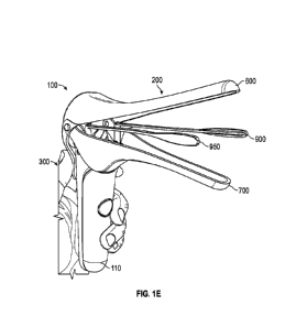
[0023] FIG. 1E is a perspective view of the speculum of FIG. 1A in an open
position.
[0024] FIG. 2 is an exploded view of the speculum of FIG. 1A.
[0025] FIG. 3 is view of an interior of a handle of the speculum of FIG. 1A.
[0026] FIG. 4A is a front perspective view of the handle of the speculum of
FIG. 1A.
[0027] FIG. 4B is a back perspective view of the handle of FIG. 4A.
[0028] FIG. 5A is aback perspective view of a handle cover of the speculum of
FIG. 1A.
-6-
CA 03009665 2018-06-22
WO 2017/117308
PCT/US2016/069043
[0029] FIG. 5B is a front perspective view of the handle cover of FIG. 5A.
[0030] FIG. 6 is a perspective view of an upper bill of the speculum of FIG.
1A.
[0031] FIG. 7 is a perspective view of a thumb tab of the speculum of FIG. 1A.
[0032] FIG. 8 is a perspective view of a lower bill of the speculum of FIG.
1A.
[0033] FIG. 9 is a perspective view of secondary bills assembly of the
speculum of FIG.
1A.
[0034] FIG. 10A is a perspective view of a right secondary bill of the
speculum of FIG. 1A.
[0035] FIG. 10B is a perspective view of a left secondary bill of the speculum
of FIG. 1A.
[0036] FIG. 11A is a top view of the slide of the speculum of FIG. 1A.
[0037] FIG. 11B is a bottom view of the slide of FIG. 10A.
[0038] FIG. 12A is a front view of a rocker of the speculum of FIG. 1A.
[0039] FIG. 12B is a back view of the rocker of FIG. 11A.
[0040] FIG. 13A is a perspective view of a pawl of the speculum of FIG. 1A.
[0041] FIG. 13B is a perspective view of a pawl according to a second
exemplary
embodiment for use with the speculum of FIG. 1A.
[0042] FIG. 14 is a perspective view of a lock strip of the speculum of FIG.
1A.
[0043] FIG. 15 is a perspective view of an illumination insert of the speculum
of FIG. 1A.
DETAILED DESCRIPTION
[0044] In the following detailed description, reference is made to the
accompanying
drawings, which form a part of the present disclosure. In the drawings,
similar symbols
typically identify similar components, unless context dictates otherwise. The
illustrative
embodiments described in the detailed description, drawings, and claims are
not meant to be
-7-
CA 03009665 2018-06-22
WO 2017/117308
PCT/US2016/069043
limiting. The detailed description is intended as a description of exemplary
embodiments and
is not intended to represent the only embodiments which may be practiced. The
term
"exemplary," as used herein, means "serving as an example, instance, or
illustration," and
should not necessarily be construed as preferred or advantageous over other
embodiments.
Other embodiments may be utilized, and other changes may be made, without
departing from
the spirit or scope of the subject matter presented here. It will be readily
understood that the
aspects of the present disclosure, as generally described herein, and
illustrated in the Figures,
can be arranged, substituted, combined, and designed in a wide variety of
different
configurations, all of which are explicitly contemplated and form part of this
disclosure.
[0045] Referring to the Figures generally, a speculum is shown. The speculum
has an
updated design relative to the antiquated, traditional two-bill design. In
some embodiments,
the speculum has two additional bills that are integrated with a speculum
having two bills.
The profile of the speculum may be narrower than traditional speculum, making
it more
comfortable for patients, because the secondary bills reduces some of the
previously
described shortcomings of the traditional design, for example, the problem of
side wall tissue
falling into the user's line of sight. In particular, while traditional
speculum typically employ
bills having a width between 20mm and 40mm, the bills of the present speculum
may have a
width between approximately 12mm and 20mm. The speculum also has an ergonomic
handle
design for increased comfort during use by the clinician.
[0046] Referring now to FIGS. 1A-1E, a speculum 100 is shown in accordance
with one
embodiment. The speculum 100 includes a bill portion 200 and a handle portion
300. The
speculum may be made of any sturdy biomaterial including metals and plastics.
The bill
portion 200 is coupled to the handle portion 300 and the bill portion is
movable between an
open position and a closed position. The bill portion 200 may be configured in
such a way
that when in the closed position, the bill portion may be wide near the handle
portion 300,
creating a cone shape as the bill portion 200 extends away from the handle
portion 300. The
bill portion 200 may maintain a constant shape after the cone, creating an
elongated shape.
[0047] When the bill portion 200 is in a closed position, as seen in FIGS. 1A-
1D, the
speculum 100 can be inserted in a patient's vagina. The bill portion 200 is
placed in line with
-8-
CA 03009665 2018-06-22
WO 2017/117308
PCT/US2016/069043
an opening of the vagina and applied a force parallel to the bill portion 200
to push the bill
portion 200 into the vagina. The user may position the speculum 100 at a depth
of the vagina
to provide a clear view of the cervix when the bill portion 200 is opened. The
speculum 100
may be inserted in a vertical direction, as seen in FIGS. 1A-1D.
Alternatively, the speculum
100 may be inserted in a horizontal direction and rotated to a vertical
position once inside the
vagina. The speculum 100 may be inserted into the vagina at a 45 degree angle
to increase the
comfort of the user. The speculum may be inserted so that an end of the bill
portion 200 are
located below the cervix. Once the bill portion 200 is opened, as seen in FIG.
1E, the cervix
may then fall into the viewing opening created by the separation of the bill
portion 200.
Alternatively, the speculum 100 may be moved around once inserted into the
vagina to
provide a clear view and adequate accessibility of the cervix.
[0048] The speculum 100 may also be equipped with a camera system. The camera
system
may provide images, video, or a combination thereof The speculum 100 may
additionally be
equipped with a system capable of transmitting images and/or video to a
monitor, allowing
the patient and/or user to simultaneously visualize the procedure. The
transmission of images
and/or video may occur wirelessly via Bluetooth, Wi-Fi, or other suitable
technology.
[0049] In some embodiments, the distal portion of the bill portion 200 may
optionally be
coated with one or more therapeutic/bioactive agents or lubricants. Examples
of suitable
bioactive agents include, but are not limited to, hormonal and non-hormonal
contraceptive
agents, cancer screening agents, vaginal spermicides, vaginal microbicides,
antibacterial
agents, antifungal agents, antiviral agents, anti-HIV agents and cancer
treatment agents, or
combinations thereof The therapeutic agents may be in any suitable formulation
that may be
applied to the surface of a vaginal speculum, such as liquid, gel and powder.
[0050] FIGS. 1A-1D may include an updated ergonomic handle in accordance with
certain
embodiments of the speculum 100. The ergonomic handle employs a greater angle
0 between
the bill portion 200 and the handle portion 300, which is more comfortable for
both the
practitioner and the patient during use. The handle portion 300 may also have
a textured grip,
for example, including bumps, dimples, and/or other texturizing elements, and
a rounded or
formed body for comfort and ergonomic benefit.
-9-
CA 03009665 2018-06-22
WO 2017/117308
PCT/US2016/069043
[0051] The handle portion 300 is positioned so as to create an angle 0 between
the bill
portion 200 and the handle portion 300. In some embodiments, the angle 0 is be
greater than
90 degrees but less than 180 degrees. In other embodiments, the angle 0 is
between 100
degrees and 180 degrees. In some embodiments the angle 0 is about 95, 100,
105, 110, 115,
120, 125, 125, 130, 135, 140, 145, 150, 155, 160, 165, 170 or 180 degrees. The
angle 0
provides a more comfortable angle for the user to insert the speculum 100 into
the vagina of
the patient. In addition, the angle 0 provides more room for the hand of the
user when
inserting the speculum 100. This reduces the risk of the hand of the user
coming in contact
with the patient when inserting the speculum 100, which can be uncomfortable
and awkward
for the patient. The angle 0 also provides a more comfortable angle for a
wrist of the user
during the procedure. This reduces the risk of injury or strain to the hand or
wrist of the user,
especially when the user completes multiple procedures in a single day, or day
after day.
[0052] FIG. 1E shows the speculum 100 in an open position. When in the open
position, the
bill portion 200 of the speculum 100 is expanded, by moving both an upper bill
600 and a
lower bill 700 away from the closed position. As shown, the upper bill 600 and
the lower bill
700 move symmetrically away from the closed position. In certain exemplary
embodiments,
opening the upper bill 600 and lower bill 700 also reveals and separates a
right secondary bill
900 and a left secondary bill 950. In the open position, the upper bill 600
and the lower bill
700 separate the tissue of the vagina, while the right and left secondary
bills 900 and 950 aid
in retaining side wall tissue of the vagina to maintain a clear viewing window
for the user.
[0053] The handle portion 300 may include a grip 110. The grip 110 may be of a
material
that provides more traction for the hand of the user. In some embodiments, the
grip 110 is
textured to provide more traction for the hand of the user. The grip 110 may
allow the user to
apply less force with the hand of the user in order to hold the speculum 100.
By allowing the
user to use less force to hold the speculum, the user may become less fatigued
when
performing the procedure. In addition, when less force is needed, the user may
experience
less cramps, strains and/or injuries caused by using the speculum 100. The
grip 110 may
extend a length of the handle portion 300. In some embodiments, the grip 110
only extends a
portion of the length of the handle portion 300. In another embodiment, the
grip 110 wraps
around the circumference of the handle portion 300. In yet another embodiment,
the grip 110
-10-
CA 03009665 2018-06-22
WO 2017/117308
PCT/US2016/069043
is a plurality of pieces spaced along the handle portion 300. In another
embodiment, the grip
110 is made of grooves located along the handle portion 300, where the grooves
align with
where fingers of the user would be located when holding the handle portion
300.
[0054] The handle 300 and/or the speculum 100 may be made of metal and/or
plastic,
including, but not limited to, titanium, aluminum, stainless steel, acrylic,
polyethylene,
polyester, polyethyleneaphthlate, polystyrene, polyvinylchloride,
polyethersulfone,
polyetherimide, polycarbonate, polysulfone, polyetheretherketone,
polyphenylsulfone, and
polymethyl methacrylate. The handle 106 may be made of a material that can be
sterilized.
The handle 106 may be made of material that is biocompatible. The handle 300
and/or the
speculum 100 may be made using a variety of techniques including, but not
limited to,
injection molding, extrusion, machining, blow molding, rotational molding,
compression
molding, transfer molding, stamping, and casting.
[0055] FIG. 2 is an expanded view of the speculum 100 with secondary bills of
FIG. 1A
showing components of the bill portion 200 and the handle portion 300. The
handle portion
300 includes a handle 400, a handle cover 500, and an actuation mechanism
including links
1600 and 1600b, and dowel 102, and a locking mechanism including a rocker
1100, a pawl
1300, a lock strip 1400, and a ball plunger 1700 (see also FIG. 3). The bill
portion 200
includes the upper bill 600, the lower bill 700, a secondary bill assembly
800, and a thumb
tab 1200. The secondary bill assembly 800 includes the right secondary bill
900, the left
secondary bill 950, and a slide 1000. The actuation mechanism causes opening
and closing of
the upper bill 600, lower bill 700, the right secondary bill 900 and the left
secondary bill 950.
Each of the components will be described in detail below.
[0056] Referring to FIGS. 4A and 4B, the handle 400 of the speculum 100 with
secondary
bills is shown. The handle 400 includes an external cover 402 and an internal
configuration
404. The external surface 402 has a rounded surface 406 that is configured to
provide an
ergonomic surface for a hand of a user (e.g., a nurse, practitioner,
physician, etc.). The
rounded surface 406 includes an aperture 408 to receive the rocker 1100. The
handle 400 also
includes a coupling portion 410 that is configured to couple the bill portion
200 to the handle
400. The coupling portion 410 includes apertures 412 to receive the lower bill
700. The
-11-
CA 03009665 2018-06-22
WO 2017/117308
PCT/US2016/069043
coupling portion 410 also includes a ridge 414 and a wall 416 that support the
lower bill 700.
The wall 416 includes a slot 418 for a link 1600b to extend through to allow
actuation of the
lower bill 700. The coupling portion 410 also includes cylindrical supports
420 that couple
the left and right secondary bills 900 and 950 to the handle 400.
100571 The internal configuration 404 includes a slide coupler 422 that
receives the slide
1000. The internal configuration 404 also includes extensions 424 that house
the pawl 1300
and provides a stop for the lock strip 1400. The internal configuration 404
also includes
screw holes 426 that provide coupling between the handle 400 and the handle
cover 500. The
internal configuration 404 also includes ledges 428 that receive links 1600 to
allow actuation
of the bill portion 200.
[0058] Referring to FIGS. 5A and 5B, the handle cover 500 of the speculum 100
is shown.
The handle cover 500 includes an external surface 502 that is configured to
provide an
ergonomic surface for a hand of the user. The external surface 502 also
includes apertures
504 that provide coupling between the handle 400 and the handle cover 500 via
screws. The
handle cover 500 also includes slots 506 that provide access for links 1600 to
connect the
handle 400 to the upper bill 600.
[0059] The handle cover 500 also includes an interior 508. The interior 508
includes ridges
510 to support the lock strip 1400. The interior 508 also includes an indent
512 that abuts the
ball plunger 1700. The interior 508 also includes guides 514 that provide
guidance of the lock
strip 1400.
[0060] Referring to FIG. 6, the upper bill 600 of the speculum 100 is shown.
The upper bill
600 includes an elongated portion 602. The elongated portion 602 may have a
width that is
larger than a height of the elongated portion 602, creating an oblong shape.
Alternatively, the
height and width of the elongated portion 602 may be configured in such a way
that when the
upper bill 600 and the lower bill 700 are closed, a circular cross section is
formed. At an end
604 of the elongated portion 602, away from a handle region 606, may be
rounded. The
rounded end 604 may provide more comfort to a patient whom will be receiving
the
speculum 100 in a cavity. The upper bill 600 and the lower bill 700 may also
be configured
such that when in the closed position, the end 604 of the upper bill 600 is
more proximal than
-12-
CA 03009665 2018-06-22
WO 2017/117308
PCT/US2016/069043
the end 704 of the lower bill 700 (in other words, lower bill 700 extends
farther than upper
bill 600), thereby the creating a gap to prevent tissue from becoming lodged
in between the
upper bill 600 and the lower bill 700 during insertion. In other embodiments,
however, the
two ends 604 and 704 may abut one another, providing no gap. The upper bill
600 and the
lower bill 700 may have a semi-circular cross section along a length of the
upper bill 600 and
the lower bill 700, where the flat portions of the semi-circles are moved
together when the
upper bill 600 and the lower bill 700 are in a closed position. Alternatively,
an outer edge and
an inner edges of the upper bill 600 and the lower bill 700 are circular, such
that when the
upper bill 600 and the lower bill 700 are in the closed position, a cross
section of the upper
bill 600 and the lower bill 700 is a ring shape. A ring shape cross section
may provide a
larger viewing opening for a user when the upper bill 600 and the lower bill
700 are in the
open position.
[0061] The upper bill 600 also includes a window frame 606. The window frame
606
includes apertures 608 to couple the upper bill 600 to the lower bill 700 and
the handle 400.
The apertures 608 may be accompanied by a slight indentation. The window frame
606 is
wider than the elongated portion 602 to provide a window 610 so that when the
upper bill
600 and the lower bill 700 are in the open position, the user has an opening
to view the
vagina and cervix. The window 610 may be circular, oblong, rectangular, or any
other shape
that would provide an opening for viewing. The window 610 should be of
sufficient size and
shape to allow the user to see the entire opening created when the upper bill
600 and the
lower bill 700 are in the open position. Referring back to FIG. 1A, the window
frame 606
extends at an angle (I) away from handle 300. In some embodiments, the angle
(I) is greater
than 25 degrees but less than 40 degrees, or any degree value or sub range of
degrees therein.
In some embodiments, the angle may be between 30 and 35 degrees. In some
embodiments
the angle (I) is about 25, 26, 27, 28, 29, 30, 31, 32, 33, 34, 35, 36, 37, 38,
39, 40, 41, 42, 43,
44, or 45 degrees.
[0062] The window frame 606 also includes an actuation region 612 that
receives a thumb
tab 1200 (see FIG. 7) to provide actuation of the upper bill 600. The
actuation region 612 also
includes a ridge 614 to secure the thumb tab 1200 in the upper bill 600. The
actuation region
612 is narrower than the viewing window 610 such that the thumb tab 1200 can
be slid into
-13-
CA 03009665 2018-06-22
WO 2017/117308
PCT/US2016/069043
the actuation region 1200. The window frame 606 also includes two indentations
616 that fit
a link 1600 on either side. The links 1600 are coupled to the window frame 606
and the
indentations 616 via the hinge pins 1800.
[0063] Referring to FIG. 7, the thumb tab 1200 is shown. The thumb tab
provides the
actuation mechanism for the speculum of the exemplary embodiment shown in the
figures.
The thumb tab 1200 includes a top surface 1202 to provide a rigid surface for
the user to
apply a force. The thumb tab 1200 also includes a groove 1204 that receives
the ridge 614 of
the upper bill 600. A top 1206 of the thumb tab has a curvature provided to
maintain an
ample viewing window for the user. A force is applied by a thumb of the user
to the thumb
tab 1200 and causes the upper bill 600 and the lower bill 700, as well as the
right and left
secondary bills 900 and 950 to separate. The force applied to the thumb tab
1200 should not
need to be a substantial force. In some embodiments, a distance the thumb tab
1200 moves
correlates to a distance the upper bill 600 and the lower bill 700 separate.
In this regard, the
user would be able to select a specific distance between the upper bill 600
and the lower bill
700 for each patient. The upper bill 600 and the lower bill 700 may open in a
continuous
fashion when force is continuously applied to the thumb tab 1200.
Alternatively, the force
applied to the thumb tab 1200 may cause the upper bill 600 and the lower bill
700 to only
open a specified distance (e.g., one fourth of the total distance the upper
bill 600 and the
lower bill 700 can separate). The user would apply force multiple times to
separate the upper
bill 600 and the lower bill 700 the desired distance.
[0064] When the force is applied to the thumb tab 1200, the opening created by
the
separation of the upper bill 600 and the lower bill 700 may be caused by both
the upper bill
600 and the lower bill 700 moving, or either the upper bill 600 and the lower
bill 700 moving.
For example, the force applied on the thumb tab 1200 may cause the upper bill
600 to move,
while lower bill 700 remains stationary.
[0065] Referring to FIG. 8, the lower bill 700 of the speculum 100 is shown.
The lower bill
700 includes an elongated portion 702. The elongated portion 702 may have a
width that is
larger than a height of the elongated portion 702, creating an oblong shape.
Alternatively, the
height and width of the elongated portion 702 may be configured in such a way
that when the
-14-
CA 03009665 2018-06-22
WO 2017/117308
PCT/US2016/069043
upper bill 600 and the lower bill 700 are closed, a circular cross section is
formed. At an end
704 of the elongated portion 702, away from an actuation region 706, may be
rounded. The
rounded end 704 may provide more comfort to a patient whom will be receiving
the
speculum 100 in a cavity.
[0066] The actuation region 706 may include extensions 708. The extensions 708
are
coupled to an exterior coupling knob 710 and an interior coupling knob 712.
The interior
coupling knob 710 couples the lower bill 700 to the handle 400. The exterior
coupling knob
712 couples the lower bill 700 to the upper bill 600.
[0067] The lower bill 700 is coupled to a link 1600b that is caused to move in
coordination
with the rotation of the upper bill 600. Specifically, the link 1600b is
coupled at a first end to
the upper bill 700 and at a second end to dowel 102. As the upper bill 600
moves between a
closed and an open position, dowel 102 moves via links 1600, which acts on
link 1600b and
thereby causes coordinated movement between the closed and the open position
of lower bill
700. In other embodiments, however, upper bill and lower bill may be
individually actuated.
In some such embodiments, upper bill and lower bill do not move simultaneously
between
the open and the closed position.
[0068] Referring to FIGS. 9-11, the secondary bill assembly 800 of the
speculum 100 is
shown. The secondary bill assembly 800 includes the right secondary bill 900
(shown in FIG.
10B), the left secondary bill 950 (shown in FIG. 10A), the slide 1000 and
dowels 103. The
right and left secondary bills 900 and 950 are substantially identical
opposites of one another.
The right and left secondary bills 900 and 950 includes arms 902 and 952. An
exterior of the
arms 902 and 952 may have a substantially flat vertical surface 904 and 954 to
provide a
clear view of the vagina and speculum once inserted by providing support to
the side tissue of
the vagina. Surfaces 904 and 954 may have a slight curve inward at the tip to
provide more
comfort when supporting the side tissue of the vagina. The right and left
secondary bills 900
and 950 may be sized to fit inside the upper bill 600 and the lower bill 700
when in the closed
position. The right and left secondary bills 900 and 950 also include
cylindrical connections
906 and 956 that receive dowels 103 to couple the right and left secondary
bills 900 and 950
to the handle 400. The right and left secondary bills 900 and 950 also include
rotation
-15-
CA 03009665 2018-06-22
WO 2017/117308
PCT/US2016/069043
elements 908 and 958 that limit the rotation of the right and left bills 900
and 950 when the
actuation mechanism moves the speculum 100 between the open position and the
closed
position. The right and left secondary bills 900 and 950 also include
horizontal protrusions
910 and 960 that include apertures 912 and 962. The apertures receive dowels
102 that couple
the right and left secondary bills 900 and 950 to the slide 1000. The
horizontal protrusions
910 and 960 are configured such the lower bill 700 abuts the protrusions 910
and 960, aiding
in movement of the slide 1000 and the right and left secondary bills 900 and
950.
[0069] The slide 1000 includes a top surface 1002 with a rounded indentation
1004 that
matches the curvature of the lower bill 700 to ensure that the slide 1000 does
not interfere
with the viewing window 610. The slide 1000 includes extensions 1006 on either
side with
protrusions 1008 that are pressed upon with movement of the upper bill 600,
thereby causing
slide 1000 to move forward. When the slide 1000 moves forward, dowels 103 held
in slot
1014 are pressed forward, thereby rotating horizontal protrusions 910 and 960
and causing
the bills 900 and 950 to open. An underside 1010 of the slide 1000 includes
stops 1012 that
limits movement of the slide 1000 when the actuation mechanism is engaged. The
slide 1000
also includes a slot 1014 that receives dowels 102 to couple the slide 1000 to
the right and
left secondary bills 900 and 950.
[0070] Referring to FIGS. 12-14, elements of a locking mechanism are shown.
The locking
mechanism includes the rocker 1100, the pawl 1300 and the lock strip 1400.
[0071] Referring to FIGS. 12A and 12B, the rocker 1100 is shown. The rocker
1100
includes an exterior face 1102 that has a curvature such that the rocker 1100
can be moved
between a first position and a second position such that a first portion 1104
of the rocker
1100 is substantially flush with the handle 400 in the first position and a
second portion 1106
of the rocker 1100 is substantially flush with the handle 400 in the second
position. To
provide rotation between the first and second position, the rocker 1100
includes knobs 1108
that couple the rocker 1100 to the handle 400. The rocker 1100 further
includes a cylindrical
housing 1110 that receives the ball plunger 1700 securing the rocker 1100 in
place inside the
handle 400. In some embodiments, the rocker 1100 is a button that is pushed to
lock/unlock
the bill portion 200 of the speculum 100 in an open position. Movement of the
rocker 1100
-16-
CA 03009665 2018-06-22
WO 2017/117308
PCT/US2016/069043
between the first position and the second position causes the rocker 1100 to
engage or
disengage the pawl 1300.
[0072] Referring to FIGS. 13A-B, two exemplary embodiments of pawl 1300 are
shown.
The pawl 1300 rests inside the extensions 424 of the handle 400, with the
knobs 1308 on
either side resting on the extensions 424. The first portion 1302 of the pawl
aligns with a top
of the extensions 424 and has a curved end 1304 that is configured to engage
with the lock
strip 1400. The pawl 1300 also includes a second portion 1306 that abuts the
rocker 1100
such that movement of the rocker 1100 either engages or disengages with the
pawl 1300,
causing rotational movement of the pawl 1300 relative to the lock strip 1400.
When the pawl
1300 is engaged with the rocker 1100, the second portion 1306 of the pawl 1300
is moved by
the rocker 1100, causing rotation of the pawl 1300 such that the first portion
1302 and
specifically the curved end 1304 of the pawl 1300 is positioned away from the
lock strip
1400. In this way, when the pawl 1300 is engaged with the rocker 1100, the
locking
mechanism is in an unlocked configuration. When the pawl 1300 is disengaged,
by moving
the rocker into the other position, the curved end 1304 of the pawl 1300 may
engage with the
lock strip 1400. In this way, when the pawl 1300 is disengaged with the rocker
1100, the
locking mechanism is in a locked position.
[0073] In the embodiment of FIG 13A, the second portion of the pawl 1306
engages with
the bottom portion of the rocker 1100. Thus, in this embodiment, when the
bottom portion of
the rocker is pressed in, the speculum is unlocked and the speculum is locked
when the top
portion of the rocker is pressed in. In the embodiment of FIG. 13B, the pawl
1300 has a
different design with an aperture 1309 through which the cylindrical housing
1110 and ball
plunger 1700 can pass, such that the second portion of the pawl 1306 engages
with the top
portion of the rocker 1100. Thus, in this embodiment, when the top portion of
the rocker is
pressed in, the speculum is unlocked and the speculum is locked when the
bottom portion of
the rocker is pressed in.
[0074] Referring to FIG. 14, the lock strip 1400 is shown. The lock strip 1400
includes a
flat portion 1402 that extends along the extensions 424 of the handle 400. An
underside of the
lock strip 1400 includes a plurality of teeth or divots 1404 (not shown) that
engage with the
-17-
CA 03009665 2018-06-22
WO 2017/117308
PCT/US2016/069043
curved end 1304 of the pawl 1300. The lock strip 1400 also includes connection
mechanisms
1406 with apertures 1408 that receive dowel 102. Dowel 102 extends a width of
the handle
400 between two links 1600 with a third link 1600 located in between the
connection
mechanism 1406. Rotation of the upper bill 600 causes movement of the exterior
links 1600,
which results in movement of the dowel 102, and ultimately, movement of the
lock strip
1400. When the lock strip moves, the divots 1404 to move into position and
interact with the
curved end 1304 of the pawl 1300. In this way, the locking mechanism locks the
bills into an
open position when the rocker 1100 is disengaged from the pawl 1300 because
the
engagement of pawl 1300 with the divots 1404 prevents movement of the lock
strip 1400 in a
direction that would allow the bills to close. When the rocker 1100 is rotated
to the second
position, engaging the pawl 1300, the pawl 1300 is moved away from the lock
strip 1400,
allowing the speculum 100 to return to the closed position by disengaging the
curved end
1304 of the pawl 1300 from the divots 1404 of the lock strip 1400. In this
unlocked
configuration, the speculum can also be opened with minimal resistance or
noise. In the
locked configuration (e.g., when the rocker 1100 is disengaged from the pawl
1300 and the
divots 1404 engage with the curved end 1304), the speculum bills may still
open, but will do
so with resistance as the curved end 1304 moves from divot 1404 to divot 1404.
[0075] In some embodiments, the speculum 100 may include a lighting module,
such as
lighting module 1500 shown in FIG. 15. The lighting module 1500 may be
positioned in the
window 610 and held in place by engagement with the window frame 606. The
lighting
module 1500 includes a base 1502 with a groove 1504 that receives the ridge
614 of the
upper bill 600. In other embodiments, the lighting module 1500 may have a snap
fit
relationship with the window frame 606. In other embodiments, the lighting
module may be
attached to the window frame 112 using fixation devices (i.e., screws, nails,
etc) or adhesive
(i.e., tape or glue). The base 1502 is configured to replace the thumb tab
1200, but function in
the same way as thumb tab 1200 for providing an actuating mechanism for
opening the bills
600 and 700. The lighting module is configured to illuminate the cavity in
which the
speculum 100 is placed in order to allow better visualization of the cavity
and execution of
procedures in the cavity. The lighting module 1500 provides one or more
illumination
elements, such as LEDs. The configuration of the lighting module 1500 provides
illumination
elements at or near the perimeter of the window 610 at window frame 606, so as
not to
-18-
CA 03009665 2018-06-22
WO 2017/117308
PCT/US2016/069043
obstruct the view of the user through the window 610. In the embodiment shown,
an
illumination element is positioned on each side of the window frame 606. The
illumination
element(s) may alternatively be positioned near any part of the window frame
606. The
illumination insert 1500 may be powered by batteries.
[0076] The speculum 100 with secondary bills 900 and 950 overcomes the
previously
described shortcomings of the traditional speculum in a variety of ways.
First, the slimmer
initial profile (in the insertion position) provides better comfort for the
patient. Furthermore,
the bill portion 200 may be capable of expanding to a variety of sizes so a
single speculum
may be appropriate for a number of patients. Also, the bill portion 200 with
the secondary
bills 900 and 950 provides the side wall support that allows the practitioner
better and less
impeded visualization and accessibility into the vagina and cervix. Finally,
the overall
updated design of the speculum 100 lessens anxiety of the patient by
eliminating the harsh-
looking metal device with sharp edges, and often employing a screw mechanism
to hold the
bill portion 200 open, with a more streamlined, softer, and overall updated
and more modern
look and feel.
[0077] For the practitioner, the features of the disclosure may reduce fatigue
and repetitive
stress injury, allow for one-handed opening and locking, allow increased
visibility and
accessibility, along with many other benefits. For the patients, these
features may reduce
patient anxiety because they employ quieter mechanism than the traditional
designs,
significantly reduce the probability of tissues and pubic hair being pinched,
and reduce
overall anxiety because of the updated look of the opening mechanism and
handles.
[0078] Some embodiments herein relate to methods of performing obstetric or
gynecological procedures utilizing speculum devices and components as
described herein
described herein. Non-limiting examples of such procedures include pelvic
exams, pap
smears, insemination, IUD insertion/removal. In some embodiments, the methods
can include
performing a plurality of such procedures in a given period of time, such as
an 8 hour or 24
hour period of time, or any sub period of time therein. Other embodiments
relate to methods
of reducing hand fatigue or repetitive use injury in a user of a device or
handle as described
herein.
-19-
CA 03009665 2018-06-22
WO 2017/117308
PCT/US2016/069043
[0079] The foregoing description details certain embodiments of the systems,
devices, and
methods disclosed herein. It will be appreciated, however, that no matter how
detailed the
foregoing appears in text, the devices and methods can be practiced in many
ways. As is also
stated above, it should be noted that the use of particular terminology when
describing certain
features or aspects of the technology should not be taken to imply that the
terminology is
being redefined herein to be restricted to including any specific
characteristics of the features
or aspects of the technology with which that terminology is associated. The
scope of the
disclosure should therefore be construed in accordance with the appended
claims and any
equivalents thereof
[0080] It will be appreciated by those skilled in the art that various
modifications and
changes may be made without departing from the scope of the described
technology. Such
modifications and changes are intended to fall within the scope of the
embodiments, as
defined by the appended claims. It will also be appreciated by those of skill
in the art that
parts included in one embodiment are interchangeable with other embodiments;
one or more
parts from a depicted embodiment can be included with other depicted
embodiments in any
combination. For example, any of the various components described herein
and/or depicted
in the Figures may be combined, interchanged or excluded from other
embodiments.
[0081] The devices, components, methods and systems described herein can be
combined
with one or more of the devices, components, methods and systems described in
any of U.S.
Patent Application entitled "Ergonomically Designed Vaginal Speculum," filed
on December
28, 2016 and identified by Atty. Docket No. 112359-0303, U.S. Patent
Application entitled
"Insertable Sleeve for Speculum and Use Thereof," filed on December 28, 2016
and
identified by Atty. Docket No. 112359-0353, and U.S. Patent Application
entitled "Sleeve for
Speculum and Use Thereof," filed on December 28, 2016 and identified by Atty.
Docket No.
112359-0403, each of which is incorporated herein by reference in its
entirety.
[0082] With respect to the use of any plural and/or singular terms herein,
those having skill
in the art can translate from the plural to the singular and/or from the
singular to the plural as
-20-
CA 03009665 2018-06-22
WO 2017/117308
PCT/US2016/069043
is appropriate to the context and/or application. The various singular/plural
permutations
may be expressly set forth herein for sake of clarity.
[0083] It will be understood by those within the art that, in general, terms
used herein, and
especially in the appended claims are generally intended as "open" terms
(e.g., the term
"including" should be interpreted as "including but not limited to," the terms
"comprising"
and "having" should, respectively, be interpreted as "comprising at least" and
"having at
least," the term "includes" should be interpreted as "includes but is not
limited to," etc.). It
will be further understood by those within the art that if a specific number
of an introduced
claim recitation is intended, such an intent will be explicitly recited in the
claim, and in the
absence of such recitation no such intent is present. For example, as an aid
to understanding,
the following appended claims may contain usage of the introductory phrases
"at least one"
and "one or more" to introduce claim recitations. However, the use of such
phrases should
not be construed to imply that the introduction of a claim recitation by the
indefinite articles
"a" or "an" limits any particular claim containing such introduced claim
recitation to
embodiments containing only one such recitation, even when the same claim
includes the
introductory phrases "one or more" or "at least one" and indefinite articles
such as "a" or
"an." In general, "a" and/or "an" should be interpreted to mean "at least one"
or "one or
more"; the same holds true for the use of definite articles used to introduce
claim recitations.
[0084] Furthermore, in those instances where a convention analogous to "at
least one of A,
B, and C, etc." is used, in general, such a construction is intended in the
sense one having
skill in the art would understand the convention (e.g., "a system having at
least one of A, B,
and C" would include but not be limited to systems that have A alone, B alone,
C alone, A
and B together, A and C together, B and C together, and/or A, B, and C
together, etc.). In
those instances where a convention analogous to "at least one of A, B, or C,
etc." is used, in
general such a construction is intended in the sense one having skill in the
art would
understand the convention (e.g., "a system having at least one of A, B, or C"
would include
but not be limited to systems that have A alone, B alone, C alone, A and B
together, A and C
together, B and C together, and/or A, B, and C together, etc.). It will be
further understood
by those within the art that virtually any disjunctive word and/or phrase
presenting two or
more alternative terms, whether in the description, claims, or drawings,
should be understood
-21-
CA 03009665 2018-06-22
WO 2017/117308
PCT/US2016/069043
to contemplate the possibilities of including one of the terms, either of the
terms, or both
terms. For example, the phrase "A or B" will be understood to include the
possibilities of
"A" or "B" or "A and B."
[0085] The technology disclosed herein has numerous applications and while
particular
embodiments of the technology have been described in detail, it will be
apparent to those
skilled in the art that the disclosed embodiments may be modified given the
design
considerations discussed herein. Therefore, the foregoing description is to be
considered
exemplary rather than limiting, and the true scope of the invention is that
defined in the
following claims.
-22-