Language selection

Search

Patent 3009703 Summary

Third-party information liability

Some of the information on this Web page has been provided by external sources. The Government of Canada is not responsible for the accuracy, reliability or currency of the information supplied by external sources. Users wishing to rely upon this information should consult directly with the source of the information. Content provided by external sources is not subject to official languages, privacy and accessibility requirements.

Claims and Abstract availability

Any discrepancies in the text and image of the Claims and Abstract are due to differing posting times. Text of the Claims and Abstract are posted:

  • At the time the application is open to public inspection;
  • At the time of issue of the patent (grant).
(12) Patent Application: (11) CA 3009703
(54) English Title: HAY RAKE TOOTH ASSEMBLY
(54) French Title: ASSEMBLAGE DE DENT D'ANDAINEUR
Status: Examination Requested
Bibliographic Data
(51) International Patent Classification (IPC):
  • A01D 80/02 (2006.01)
(72) Inventors :
  • ROWSE, RODNEY D. (United States of America)
  • WORDEN, RANDY L. (United States of America)
(73) Owners :
  • ROWSE HYDRAULIC RAKES CO., INC. (United States of America)
(71) Applicants :
  • ROWSE HYDRAULIC RAKES CO., INC. (United States of America)
(74) Agent: MACRAE & CO.
(74) Associate agent:
(45) Issued:
(22) Filed Date: 2018-06-27
(41) Open to Public Inspection: 2019-02-21
Examination requested: 2023-05-16
Availability of licence: N/A
(25) Language of filing: English

Patent Cooperation Treaty (PCT): No

(30) Application Priority Data:
Application No. Country/Territory Date
15/681,610 United States of America 2017-08-21

Abstracts

English Abstract


A hay rake tooth assembly having a base plate. One or more tines that extend
through
and are captured by one or more holes in the base plate. A molding connected
to the base
plate and molded about the tine extends.


Claims

Note: Claims are shown in the official language in which they were submitted.

What is claimed is:
1. A hay rake tooth assembly, comprising:
a base plate having an elongated member with at least one hole;
a tine that extends through and is captured by the base plate; and
a molding connected to the base plate and molded about the tine.
2. The assembly of claim 1 wherein the at least one hole is swedged.
3. The assembly of claim 1 wherein the base plate has connecting holes and
the at least
one hole is between the connecting hole and an end of the elongated member.
4. The assembly of claim 1 wherein the tine has a finger section and a head
section.
5. The assembly of claim 1 wherein the tine has a head section that is
conical in shape.
6. The assembly of claim 1 wherein the tine has a swedged head section that
is captured
by and engages a swedged portion of the at least one hole.
3


Description

Note: Descriptions are shown in the official language in which they were submitted.


HAY RAKE TOOTH ASSEMBLY
BACKGROUND OF THE INVENTION
This invention is directed to a hay rake tooth assembly and more particularly
a hay rake
tooth assembly having a stronger and more resilient construction.
Hay rake assemblies are well-known in the art and typically include a rake
wheel having
a plurality of tooth assemblies mounted to the wheel. An example of a
conventional hay rake
tooth is found in U.S. Pat. No. 3,401,515. As shown in Figure 1, prior art
tooth assemblies 1
include a base plate 2, a rubber molding 3 attached to the base plate 2, and a
tine 4 that
.. extends from within the rubber molding 3 outwardly away from the base plate
2. Some tines 4
are configured at a base end 5 to have an L-shape or a loop to reduce the
possibility of the tine
4 being pulled out of the molding 3.
With this prior art design, when the tine 4 is molded and is held in place by
hole 6 which
is made near the base of the molding on each side, that is in communication
with the bore 7 in
.. the molding 3 that receives a pin to hold the tine 4. However, the hole 6
weakens the structural
integrity of molding 3. Further, since the tine 4 is retained only by the
molding 3, when the
molding fatigues, or is stressed beyond its limitations, the molding 3 breaks
and the tine 4 is
released into the field where the tine 4 can puncture an implement tire, be
run through a field
chopper, or interfere with production in some other way. Accordingly, a need
exists in the art for
a tooth assembly that addresses these needs.
Therefore, an objective of the present invention is to provide a tooth
assembly that is
stronger and more resilient.
Another objective of the present invention is to provide a tooth assembly that
better
retains a tine 4 under stress or fatigue.
These and other objectives will be apparent to one skilled in the art based
upon the
following written description, claims, and drawings.
SUMMARY OF THE INVENTION
A hay rake tooth assembly having an elongated base plate having one or more
holes
that are preferably swedged or cupped. Tines having a finger section and a
head section that
are inserted through the holes in the base plate such that the head section of
the tine is
captured and retained by the base plate.
1
CA 3009703 2018-06-27

A molding is formed about the tine and attached to the base plate.
BRIEF DESCRIPTION OF THE DRAWINGS
Fig. 1 is a side sectional view of a prior art tooth assembly;
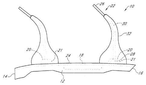
Fig. 2 is a side sectional view of a tooth assembly;
Fig. 3 is atop plan view of a base plate;
Fig. 4 is a side view of a base plate; and
Fig. 5 is a side sectional view of a tooth assembly.
.. DETAILED DESCRIPTION OF THE PREFERRED EMBODIMENT
Referring to the Figures, a hay rake tooth assembly 10 has a base plate 12
that is
secured to a raking wheel (not shown). The base plate 12 is an elongated
member having a
first end 14, a second end 16, and a connecting hole 18 about halfway between
the ends 14
and 16. The connecting hole 18 receives a bolt or the like to connect the base
plate 12 to the
wheel.
Positioned between the ends 14 and 16 and the connecting hole 18 are a pair of
holes
for receiving tines 22. Preferably, the holes 20 are swedged or cupped
upwardly 21 away
from a top surface 24 of the base plate 12.
The tines 22 have a finger section 26 that extends away from the head section
28. The
20 head section 28 is greater in diameter than the finger section 26 and
preferably is conical in
shape or swedged so that the finger section 26 will extend through the hole 20
while the head
section 28 is captured by and engages the swedge portion of base plate 22. A
molding 32,
which totally encloses the tine 22 with no positioning holes to weaken the
molding 32, is formed
about the tine connected to the base plate 12.
Once assembled, the tines 22 are able to move adequately to perform their
intended
function while being secured to the base plate 12. If the molding 32 were to
fail, the base plate
12 would still retain the tines 22.
In an alternative embodiment, instead of holes 20, the base plate 12 has a
connecting
member 34 such as a loop or the like. The head section 28 of the tine 22 would
also have a
.. connecting member 36 that would connect and/or interlock the base plate 12
and the tine 22.
Accordingly, a tooth assembly 10 has been disclosed that, at the very least,
meets all
the stated objectives.
2
CA 3009703 2018-06-27

Representative Drawing
A single figure which represents the drawing illustrating the invention.
Administrative Status

For a clearer understanding of the status of the application/patent presented on this page, the site Disclaimer , as well as the definitions for Patent , Administrative Status , Maintenance Fee  and Payment History  should be consulted.

Administrative Status

Title Date
Forecasted Issue Date Unavailable
(22) Filed 2018-06-27
(41) Open to Public Inspection 2019-02-21
Examination Requested 2023-05-16

Abandonment History

There is no abandonment history.

Maintenance Fee

Last Payment of $277.00 was received on 2024-05-22


 Upcoming maintenance fee amounts

Description Date Amount
Next Payment if standard fee 2025-06-27 $277.00
Next Payment if small entity fee 2025-06-27 $100.00

Note : If the full payment has not been received on or before the date indicated, a further fee may be required which may be one of the following

  • the reinstatement fee;
  • the late payment fee; or
  • additional fee to reverse deemed expiry.

Patent fees are adjusted on the 1st of January every year. The amounts above are the current amounts if received by December 31 of the current year.
Please refer to the CIPO Patent Fees web page to see all current fee amounts.

Payment History

Fee Type Anniversary Year Due Date Amount Paid Paid Date
Application Fee $400.00 2018-06-27
Maintenance Fee - Application - New Act 2 2020-06-29 $100.00 2020-06-05
Maintenance Fee - Application - New Act 3 2021-06-28 $100.00 2021-05-25
Maintenance Fee - Application - New Act 4 2022-06-27 $100.00 2022-05-24
Maintenance Fee - Application - New Act 5 2023-06-27 $210.51 2023-05-03
Request for Examination 2023-06-27 $816.00 2023-05-16
Maintenance Fee - Application - New Act 6 2024-06-27 $277.00 2024-05-22
Owners on Record

Note: Records showing the ownership history in alphabetical order.

Current Owners on Record
ROWSE HYDRAULIC RAKES CO., INC.
Past Owners on Record
None
Past Owners that do not appear in the "Owners on Record" listing will appear in other documentation within the application.
Documents

To view selected files, please enter reCAPTCHA code :


To view images, click a link in the Document Description column. To download the documents, select one or more checkboxes in the first column and then click the "Download Selected in PDF format (Zip Archive)" or the "Download Selected as Single PDF" button.

List of published and non-published patent-specific documents on the CPD .

If you have any difficulty accessing content, you can call the Client Service Centre at 1-866-997-1936 or send them an e-mail at CIPO Client Service Centre.


Document
Description 
Date
(yyyy-mm-dd) 
Number of pages   Size of Image (KB) 
Request for Examination 2023-05-16 2 37
Abstract 2018-06-27 1 6
Description 2018-06-27 2 94
Claims 2018-06-27 1 19
Drawings 2018-06-27 5 31
Amendment 2018-06-27 1 30
Representative Drawing 2019-01-16 1 7
Cover Page 2019-01-16 1 26