Note: Descriptions are shown in the official language in which they were submitted.
LONGITUDINAL GATE HOPPER CAR WITHOUT PARTITIONS
TECHNICAL FIELD
Particular embodiments relate generally to railcars, and more particularly to
a hopper
car with a single hopper, a single discharge opening, and/or a single
longitudinal gate (i.e., no
partitions).
BACKGROUND
Railway hopper cars transport and sometimes store bulk materials. Hopper cars
generally include one or more hoppers which may hold cargo or lading during
shipment.
Hopper cars are frequently used to transport coal, sand, metal ores,
aggregates, grain and any
other type of lading which may be satisfactorily discharged through openings
formed in one
or more hoppers. Discharge openings are typically provided at or near the
bottom of each
hopper to rapidly discharge cargo. A variety of door assemblies or gate
assemblies along
with various operating mechanisms have been used to open and close discharge
openings
associated with railway hopper cars.
Transversely oriented discharge openings and gates are frequently coupled with
a
common linkage operated by an air cylinder. The air cylinder is typically
mounted in the
same orientation as the operating gate linkage which is often a longitudinal
direction relative
to the associated hopper.
Longitudinally oriented discharge openings and doors are often used in pairs
that may
be rotated or pivoted relative to the center sill or side sills of a hopper
car. Longitudinally
oriented discharge openings and doors may be coupled with a beam operated by
an air
cylinder. The air cylinder is typically mounted in the same orientation as the
operating beam
which is often a longitudinal direction relative to the associated hopper. The
operating beam
may be coupled to the discharge doors by door struts that push (or pull) the
gates open or pull
(or push) them closed as the air cylinder moves the operating beam back and
forth.
Hopper cars may be classified as open or covered (enclosed). Hopper cars may
have
relatively short sidewalls and end walls or relatively tall or high sidewalls
and end walls.
The sidewalls and end walls of many hopper cars are often formed from steel or
aluminum
sheets and reinforced with a plurality of vertical side stakes or support
posts. Some hopper
1
CA 3009792 2018-06-28
cars include interior frame structures or braces to provide additional support
for the
sidewalls.
SUMMARY
Currently, covered hopper cars with longitudinal openings and gates are
configured
with two, three, or four sets of openings and gates with partition sheets
separating the car into
bays. The openings and covering gates are generally a fixed size that is
shorter than the bays.
Thus, sloped sheets are used to direct the lading into the gate during
discharging of the
hopper car. The sloped sheets result in a triangular shaped void area between
bays where no
lading is carried. The void space is disadvantageous because the hopper car is
made longer
to replace the lost volume.
Particular embodiments generally include a hopper car with a single bay, a
single
longitudinally oriented opening that extends the length of the bay, and one or
more
longitudinal gates that extend the length of the opening.
According to some embodiments, a railcar comprises an underframe, a pair of
sidewall assemblies, a pair of end wall assemblies, and one hopper bay formed
between the
pair of sidewall assemblies and the pair of end wall assemblies. The one
hopper bay includes
a longitudinal discharge opening extending the length of the hopper bay.
In particular embodiments, the one hopper bay extends the length of the
railcar. The
railcar may further comprise one or more longitudinal discharge gates coupled
to the hopper
bay and configured to cover the longitudinal discharge opening, wherein the
one or more
longitudinal discharge gates are movable away from the longitudinal discharge
opening,
thereby allowing lading within the hopper to discharge through the
longitudinal opening.
According to some embodiments, a hopper for a railcar comprises a longitudinal
discharge opening extending the length of the hopper. The hopper extends the
length of a
railcar when coupled to the railcar.
In particular embodiments, the hopper further comprises one or more
longitudinal
discharge gates coupled to the hopper and configured to cover the longitudinal
discharge
opening. The one or more longitudinal discharge gates are movable away from
the
longitudinal discharge opening, thereby allowing lading within the hopper to
discharge
through the longitudinal opening.
2
CA 3009792 2018-06-28
According to some embodiments, a railcar comprises a pair of trucks disposed
near
each end of the railcar and coupled to a center sill. One hopper is disposed
between the pair
of trucks and coupled to the center sill. The one hopper includes a
longitudinal discharge
opening extending the length of the hopper.
In particular embodiments, the one hopper extends from one truck of the pair
of
trucks to the other truck of the pair trucks. The railcar may further comprise
one or more
longitudinal discharge gates coupled to the hopper bay and configured to cover
the
longitudinal discharge opening. The one or more longitudinal discharge gates
are movable
away from the longitudinal discharge opening, thereby allowing lading within
the hopper to
discharge through the longitudinal opening.
As a result, particular embodiments of the present disclosure may provide
numerous
technical advantages. For example, because the discharge opening is not
shorter than the
bay, the need for a partition sheet is eliminated. The triangular void space
created by the
partition sheet is also eliminated. The hopper car can be shortened while
transporting the
same volume. A shorter hopper car reduces overall train length and improves
operation on
the railroad. In some embodiments, eliminating the partition sheet saves
weight and reduces
cost. Particular embodiments of the present disclosure may provide some, none,
all, or
additional technical advantages.
BRIEF DESCRIPTION OF THE DRAWINGS
For a more complete understanding of the particular embodiments, and the
advantages thereof, reference is now made to the following written description
taken in
conjunction with the accompanying drawings, in which:
FIGURE 1 is a schematic drawing in elevation showing a side view of an example
hopper car;
FIGURE 2 is a schematic drawing in elevation showing a side view of an example
hopper car highlighting the void space between hopper bays;
FIGURE 3 is a schematic drawing in elevation showing a side view of an example
hopper car with a single hopper bay and longitudinal discharge gate, according
to a particular
embodiment; and
3
CA 3009792 2018-06-28
FIGURE 4 is a block diagram illustrating longitudinal discharge doors
underneath an
example hopper car, according to a particular embodiment.
DETAILED DESCRIPTION
Railway hopper cars generally include two or more hoppers which may hold cargo
or
lading (e.g., bulk materials) during shipment. Hopper cars may be classified
as open or
covered (enclosed). Hopper cars may have relatively short sidewalls and end
walls or
relatively tall or high sidewalls and end walls. The sidewalls and end walls
of many hopper
cars are often formed from steel or aluminum sheets and reinforced with a
plurality of
vertical side stakes or support posts. Some hopper cars include interior frame
structures or
braces to provide additional support for the sidewalls. Alternatively, covered
hoppers may be
built with a monocoque body design employing a curved roof and sides which
provide the
structural support for the car body and obviate the need for external side
stakes.
Hopper cars frequently transport coal, sand, metal ores, aggregates, grain,
plastic
pellets, and any other type of lading which may be satisfactorily discharged
through openings
formed in one or more hoppers. Discharge openings are typically provided at or
near the
bottom of each hopper to rapidly discharge cargo. Discharge openings in
conventional
hopper cars are of fixed size, which limits the geometry of usable volume
within hopper cars.
A variety of door assemblies or gate assemblies along with various operating
mechanisms
have been used to open and close discharge openings associated with railway
hopper cars.
Using fixed discharge openings requires multiple hoppers to carry a certain
volume of
cargo with a certain discharge rate. The use of multiple hoppers creates a
substantial amount
of empty and unusable space between each hopper, under the peak of the
longitudinal hopper
sheets (the "cross-ridge") of the car which separates the compartments.
Lengthening the car
to increase the volumetric capacity also increases the distance between
hoppers, which raises
the intersection point between hopper sheets, thereby further increasing the
volume of empty
and unusable space. Furthermore, as the car is lengthened, it must also be
narrowed to
maintain compliance with regulatory clearance requirements, further reducing
the marginal
volume increase gained by lengthening the car.
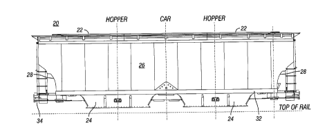
FIGURE 1 is a schematic drawing in elevation showing a side view of an example
hopper car. Hopper car 20 may be generally described as a covered hopper car,
and may
4
CA 3009792 2018-06-28
carry bulk materials such as sand, sugar, grain, and other agricultural
products. Other hopper
cars, however, may include open hopper cars, which typically carry coal, metal
ores,
aggregates or ballast, or any other cars suitable for carrying bulk lading.
Hopper car 20 includes compartments 22 each with hopper 24. Hoppers 24 may be
opened and closed to control discharge of lading from compartments 22. As
illustrated,
hopper car 20 includes two compartments (or bays) 22. Hoppers 24 may include
transverse
or longitudinal discharge gates.
Compartment 22 is configured to carry bulk materials and the interior walls of
compartment 22 are generally sloped towards hopper 24 to facilitate discharge
of the lading.
Multiple compartments 22 may be separated by interior bulkheads or partitions
(as illustrated
in more detail in FIGURE 2).
Hopper car 20 may include a pair of sidewall assemblies 26 and sloped end wall
assemblies 28 mounted on a railway car underframe. The railway car underframe
includes
center sill 34 and a pair of shear plates 30. A pair of side sills 32 provide
support for
sidewall assemblies 26.
Center sill 34 is a structural element for carrying the loads of the hopper
car. Center
sill 34 transfers the various longitudinal forces encountered during train
operation from car to
car. Shear plates 30 extend generally parallel with center sill 34 and are
spaced laterally
from opposite sides of center sill 34.
FIGURE 2 is a schematic drawing in elevation showing a side view of an example
hopper car highlighting the void space between hopper bays. Hopper car 20
includes
compartment 22a and compartment 22b. Within hopper car 20, compartment 22a is
separated from compartment 22b by partition 37. Partition 37 may comprise a
steel partition.
Partition 37 may also be referred to as a partition sheet. Partition 37
extends transversely
across the interior of hopper car 20 from one sidewall assembly 26 to the
other sidewall
assembly 26.
Partition slope sheet 38 is coupled to partition 37 to direct lading to hopper
24. For
example, partition slope sheet 38a directs lading to hopper 24a, and partition
slope sheet 38b
directs lading to hopper 24b. Partition slope sheet 38 may comprise a steel
partition.
Partition slope sheet 38 extends transversely across the interior of hopper
car 20 from one
sidewall assembly 26 to the other sidewall assembly 26.
5
CA 3009792 2018-06-28
Partition slope sheets 38a and 38b may intersect at partition 37, forming a
triangular
area beneath partition slope sheets 38a and 38b. The triangular area under
partition slope
sheets 38a and 38b is space that cannot be used for transporting a commodity.
For example,
cargo must be carried above partition slope sheets 38a and 38b for partition
sheets 38a and
38b to direct the cargo or landing to hoppers 24a and 24b, respectively. To
increase the
volume of hopper car 20 to make up for the void space, hopper car 20 may be
lengthened.
Because the discharge openings are of a fixed size, lengthening hopper car 20
requires
partition slope sheets 38a and 38b to extend longer from partition 37. At a
certain point,
however, slope sheets 38a and 38b may have a slope that does not facilitate
directing lading
to hoppers 24a and 24b.
For example, certain lading may have an effective viscosity that gravity
overcomes to
discharge through hoppers 24a and 24b when open. If the slopes are too lowly
graded, then
gravity may not overcome the viscosity and residual lading may reside in
hopper car 20
and/or the discharge rate may be reduced. To overcome the limitation, the
conventional
solution is to increase the number of openings and hoppers, thereby
introducing additional
partitions 37, which further increases the amount of unusable volume.
Particular embodiments obviate the problems described above and include a
hopper
car with a single hopper bay with one or more longitudinal discharge openings
extending the
entire length of the bay. Some embodiments may include a longitudinal gate
that covers the
longitudinal discharge openings. Because the discharge opening is not shorter
than the
length of the bay, the partition sheet is not needed. The triangular void
space is also
eliminated, and the hopper car can be shortened while transporting the same
volume. A
shorter hopper car reduces overall train length and improves operation on the
railroad. In
some embodiments, eliminating the partition sheet saves weight and reduces
cost.
Particular embodiments are described with reference to FIGURES 3 and 4 of the
drawings. Like numbers may be used for like and corresponding parts of the
various
drawings.
FIGURE 3 is a schematic drawing in elevation showing a side view of an example
hopper car with a single hopper bay and longitudinal discharge opening,
according to a
particular embodiment. Hopper car 40 be generally described as a covered
hopper car and
may carry bulk materials such as sand, sugar, grain, and other agricultural
products, for
6
CA 3009792 2018-06-28
example. Other hopper cars, however, may include open hopper cars, which may
carry coal,
metal ores, aggregates, ballast, etc. Hopper car 40 includes one compartment
42 with hopper
44. Hopper 44 may be opened and closed to control discharge of lading from
compartment
42. Hopper 44 comprises a longitudinal discharge opening and gate, as
described in further
detail in FIGURE 4.
Compartment 42 is configured to carry bulk materials and the interior walls of
compartment 42 are generally sloped towards the discharge opening of hopper 44
to facilitate
discharge of the lading. With a single compartment 42, interior bulkheads or
partitions are
not required.
The flow rate of the lading of single compartment 42 may be controlled by the
size of
the discharge opening in hopper 44. In some embodiments, the discharge opening
of hopper
44 may extend the length of hopper car 40 to facilitate a sufficiently high
discharge rate of
lading from single compartment 42 and ensure that substantially all lading is
discharged.
The size of the opening of hopper 44 may be adjusted based on the desired car
capacity, including the desired length of hopper car 40. The size of the
discharge opening of
hopper 44 may also be adjusted.
In some embodiments, hopper 44 includes a single discharge opening. In some
embodiments, hopper 44 may include two longitudinal discharge openings, one on
each side
of center sill 34, for example.
Hopper car 40 may include a pair of sidewall assemblies 26 and sloped end wall
assemblies 28 mounted on a railway car underframe. The railway car underframe
includes
center sill 34, trucks 28, and a pair of shear plates 30. A pair of side sills
32 provide support
for sidewall assemblies 26.
Center sill 34 is a structural element for carrying the loads of hopper car
40. Center
sill 34 transfers the various longitudinal forces encountered during train
operation from car to
car. Shear plates 30 extend generally parallel with center sill 34 and are
spaced laterally
from opposite sides of center sill 34.
Hopper car 40 may transport the same volume of commodity as hopper car 20, but
in
a shorter length car. The overall length of hopper car 40 may be shorter than
hopper car 20
because hopper car 40 does not include ridges between multiple hopper bays.
For example,
the triangular void areas between partition slope sheets 38a and 38b may be
eliminated by
7
CA 3009792 2018-06-28
having the opening of discharge assembly 60 extend along a substantial portion
of the length
of hopper car 40.
FIGURE 4 is a block diagram illustrating longitudinal discharge doors
underneath an
example hopper car, according to a particular embodiment. FIGURE 4 illustrates
a discharge
assembly 60 that may be coupled to hopper 44 illustrated in FIGURE 3. In
particular
embodiments, discharge assembly 60 comprises operating beam 62, discharge
doors 64,
guides 66, door struts 68, and operating cylinder 70.
Operating beam 62 is coupled to center sill 34 by guides 66. Operating beam 62
is
coupled to discharge door 64 by door struts 68. Operating cylinder 70 is
coupled to
operating beam 62 and is operable to move operating beam 62 back and forth
through guides
66.
Operating beam 62 may comprise a steel box beam, may be extruded from aluminum
or steel, may be pultruded as a fiber reinforced composite, such as a fiber or
carbon
composite, or any other suitable material.
Portions of slope sheet 36 cooperate with adjacent portions of center sill 34
to define
longitudinal discharge openings. Longitudinal discharge openings may be
disposed along
opposite sides of center sill 34. The longitudinal discharge openings may
extend the length
of hopper car 40 or the length of compartment 42. The discharge openings may
be optimized
for the specific hopper car 40 to maximize its volumetric capacity.
Discharge doors 64 are hinged proximate to center sill 34. Various types of
mechanical hinges may engage discharge doors 64 with center sill 34. Discharge
doors 64
may be oriented longitudinally and extend the length of the longitudinal
discharge openings.
Discharge doors 64 may be configured to match the longitudinal discharge
openings and
extend along the length of hopper car 40.
Discharge doors 64 are illustrated in the closed position, which prevents the
discharge
of lading through the longitudinal discharge openings. In operation, operating
cylinder 70
moves operating beam 62 through guides 66 to open discharge doors 64 via door
struts 68.
At a first end, door struts 68 are rotationally coupled to operating beam 62.
At a
second end, door struts 68 are rotationally coupled to discharge door 64. In
particular
embodiments, rotational coupling may be achieved via ball joints.
8
CA 3009792 2018-06-28
Operating cylinder 70 is operable to move operating beam 62 back and forth
through
guides 66. In particular embodiments, operating cylinder 70 may comprise a
pneumatic
cylinder, or any type of motor suitable for moving operating beam 62 in a
longitudinal
direction.
Longitudinal movement of operating beam 62 results in radial extension of door
struts
68 to move discharge doors 64 from their open position to their closed
position. Movement
of operating beam 62 in the opposite direction results in pulling, pushing, or
moving
discharge doors from their closed position to their open position which allows
rapid
discharge of any lading contained within railway hopper car 20.
Although FIGURE 4 illustrates a particular type of longitudinal gate, some
embodiments may include other configurations of hinge operated longitudinal
gates or other
types of longitudinal gates, such as sliding longitudinal gates.
herein
components, the phrase "same length" refers to substantially the same length
or
approximately the same length. For example, when a discharge opening is
described as the
same length as a hopper, the discharge opening may be substantially or
approximately the
same length as the hopper accounting for any supporting structure (e.g., cross
members,
braces, etc.) at each end of the hopper. Similarly, when a hopper or discharge
opening is
referred to as extending the length of the railcar, the hopper or discharge
opening extends the
length of the railcar usable for transporting lading (e.g., excluding end
portions reserved for
other components, such as the coupling equipment, ladders, etc. illustrated in
FIGURES 1-3).
Thus, the exact measurements of the two components may differ, but the
components may be
referred to as the same length for purposes of comparison and description
herein.
Certain embodiments may facilitate a variety of gate sizes and shapes, which
may be
optimized based on the density and flow characteristics of any desired
commodity hauled in
hopper car 40. An advantage is that particular embodiments improve upon design
constraints
imposed by currently used conventional gates that prevent such optimization.
Further, the
longitudinal discharge openings may facilitate the reduction of one or more
compartments
and provide for a more efficient car design by removing much of the unused
space which
exists under the cross-ridge in current car designs. More efficient use of the
cross-sectional
area of the car facilitates the overall length of covered hopper cars to be
substantially
9
CA 3009792 2018-06-28
reduced, with the potential of increasing the number of cars and the resulting
tonnage in a
given length of train.
Although particular embodiments and their advantages have been described in
detail,
it should be understood that various changes, substitutions and alternations
can be made
herein without departing from the spirit and scope of the embodiments.
CA 3009792 2018-06-28