Note: Descriptions are shown in the official language in which they were submitted.
CA 03009886 2018-06-27
WO 2017/116847 PCT/US2016/067746
POWER OUTLET HAVING AVAILABILITY NOTIFICATION
RELATED APPLICATIONS
[0001] The present application claims priority to U.S. Provisional
Application No.
62/273,183, filed December 30th, 2015, the entire contents of which are hereby
incorporated.
TECHNICAL FIELD
[0002] The present invention relates to electrical power outlets, such as
but not limited to,
duplex outlets, Universal Serial Bus (USB) outlets, low-voltage outlets, and
outlets having
ground fault circuit interrupter (GFCI) protection.
SUMMARY
[0003] In one embodiment, the invention provides an electrical receptacle
including an
outlet, a shutter, and a switch. The outlet is configured to receive an
electrical device. The
shutter is configured to move from a first position to a second position when
the electrical device
is received. The switch is configured to output a signal when the shutter
moves from the first
position to the second position.
[0004] In another embodiment the invention provides an electrical
receptacle including an
outlet and a switch. The outlet is configured to receive an electrical device.
The switch is
configured to determine when the electrical device is received and output a
signal when the
electrical device is received.
[0005] In another embodiment the invention provides a notification system
including an
electrical receptacle and a notification control unit. The electrical
receptacle includes an
outlet configured to receive an electrical device and a switch. The switch is
configured to
determine when the electrical device is received and output a signal when the
electrical device is
received. The notification control unit is configured to receive the signal,
determine a state of
the electrical receptacle based on the signal, and output the state of the
electrical receptacle.
[0006] In another embodiment the invention provides a method of providing
an availability
status of an electrical receptacle. The method including determining when the
electrical
1
CA 03009886 2018-06-27
WO 2017/116847 PCT/US2016/067746
receptacle receives an electrical device; outputting, from the electrical
receptacle, a signal when
the electrical device is received; determining, via a processing unit, the
availability status the
electrical receptacle; and outputting the availability status to a user
device.
[0007] Other aspects of the invention will become apparent by consideration
of the detailed
description and accompanying drawings.
BRIEF DESCRIPTION OF THE DRAWINGS
[0008] Fig. 1 is a block diagram illustrating a notification system
according to some
embodiments of the application.
[0009] Fig. 2 is a block diagram of the power receptacle of the
notification system of Fig. 1
according to some embodiments of the application.
[0010] Fig. 3 is a perspective view of the power receptacle of Fig. 2
according to some
embodiments of the application.
[0011] Fig. 4 is a perspective view of the power receptacle of Fig. 3
receiving an electrical
device, according to some embodiments of the application.
[0012] Fig. 5 illustrates a cross-sectional view of the power receptacle of
Fig. 3 taken along
line A-A, according to some embodiments of the application.
[0013] Fig. 6 illustrates a cross-sectional view of the power receptacle of
Fig. 3, receiving an
electrical device, taken along line A-A, according to some embodiments of the
application.
[0014] Fig. 7 illustrates a cross-sectional view of the power receptacle of
Fig. 3 taken along
line A-A, according to some embodiments of the application.
[0015] Fig. 8 illustrates a map displayed on a user device of the
notification system of Fig. 1,
according to some embodiments of the application.
[0016] Fig. 9A is a front perspective view of a notification system
according to another
embodiment of the application.
2
CA 03009886 2018-06-27
WO 2017/116847 PCT/US2016/067746
[0017] Fig. 9B is a rear perspective view of the notification system of
Fig. 9A according to
some embodiments of the application.
[0018] Fig. 10A is a front perspective view of a power receptacle of Fig.
9A according to
some embodiments of the application.
[0019] Fig. 10B is a rear perspective view of the power receptacle of Fig.
10A according to
some embodiments of the application.
DETAILED DESCRIPTION
[0020] Before any embodiments of the application are explained in detail,
it is to be
understood that the application is not limited in its application to the
details of construction and
the arrangement of components set forth in the following description or
illustrated in the
following drawings. The application is capable of other embodiments and of
being practiced or
of being carried out in various ways.
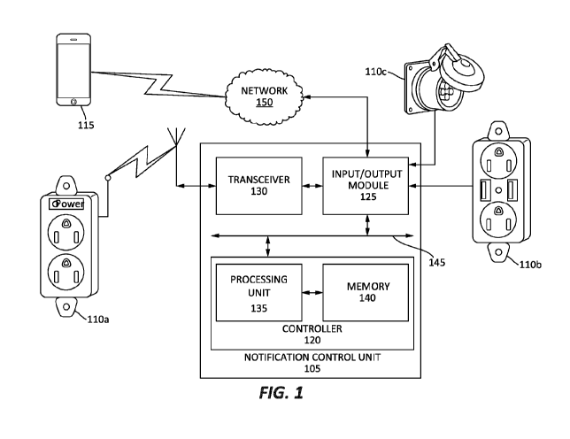
[0021] Fig. 1 illustrates a notification system 100 according to some
embodiments of the
application. The notification system 100 includes a notification control unit
105, one or more
power receptacles 110a-110c, and one or more user devices 115. In the
illustrated embodiment,
power receptacle 100a may communicate with the notification control unit 105
wirelessly, while
power receptacles 110b, 110c may communicate with the notification control
unit 105 via a
wired connection. Further, as illustrated, power receptacles 110a may be a
standard duplex
receptacle, power receptacle 110b may be a duplex receptacle include Universal
Serial Bus
(USB) ports, and power receptacle 110c may be a low-voltage port (e.g., a
class 2 low-voltage
port). In other embodiments, power receptacles 110 may be, but are not limited
to, 240-volt
receptacles, Universal Serial Bus (USB) outlets, or power receptacles having a
combination of
various electrical ports. In some embodiments, the power receptacle 110 may
include ground
fault circuit interrupter (GFCI) circuitry and components. The one or more
user devices 115 may
include, but are not limited to, smart phones, tablets, laptop computers, or
any internet-enabled
devices.
3
CA 03009886 2018-06-27
WO 2017/116847 PCT/US2016/067746
[0022] The notification control unit 105 may include, among other things, a
controller 120,
an input/output module 125, and a transceiver 130. The controller 120 may
include a processing
unit 135 and a memory 140. The controller 120 may implement certain methods
described
herein.
[0023] It should be appreciated by those of ordinary skill in the art that
Fig. 1 depicts the
notification control unit 105 in a simplified manner, and an actual
implementation may include
suitably configured power components and processing logic to support known or
conventional
features. The components of the controller 120 may be communicatively coupled
to one another
via a local interface 145. The local interface 145 may include, for example,
one or more buses or
other connections.
[0024] The processing unit 135 is a hardware device for executing software
instructions.
The processing unit 135 may be a microprocessor or other similar device. The
memory 140
includes, for example, a program storage area and a data storage area. The
program storage area
and the data storage area can include combinations of different types of
memory, such as read-
only memory (ROM), random access memory (RAM) or other suitable magnetic,
optical,
physical, or other non-transitory computer readable medium. The processing
unit 135 is
connected to the memory 140 and executes software instructions that are
capable of being stored
in a random access memory (RAM) of the memory 140 (e.g., during execution), a
read-only
memory (ROM) of the memory 140 (e.g., on a generally permanent basis). The
software may
include, one or more applications, program data, filters, rules, one or more
program modules, and
other executable instructions.
[0025] The input/output module 125 is configured to provide communication
between the
notification control unit 105 and outside devices. In the illustrated
embodiment, the input/output
module 125 provides communication between the notification control unit 105
and the one or
more power receptacles 110a-110c. Additionally, in the illustrated embodiment,
the input/output
module 125 provides communication between the notification control unit 105
and the one or
more user devices 115, through the network 150.
[0026] The transceiver 130, along with the transceiver antenna 155, enables
wireless
communication from the notification control unit 105 to, for example, the one
or more power
4
CA 03009886 2018-06-27
WO 2017/116847 PCT/US2016/067746
receptacles 110a. In other embodiments, rather than a transceiver 130 and
transceiver antenna
155, the notification control unit 105 may include separate transmitting and
receiving
components, for example, a transmitter, a transmitting antenna, a receiver,
and a receiving
antenna. The wireless communication between the notification control unit 105
and the one or
more power receptacles 110a may use a variety of different communications
protocols, such as
but not limited to, Bluetooth, ZigBee, Wifi, and a wireless personal area
network (WPAN).
[0027] Fig. 2 is a block diagram of the power receptacle 110 according to
one embodiment
of the application. It should be appreciated by those of ordinary skill in the
art that Fig. 2 depicts
the power receptacle 110 in a simplified manner, and an actual implementation
may include
suitably configured power components and processing logic to support known or
conventional
features. The power receptacle 110 includes a receptacle controller 200, one
or switches 205,
and a receptacle input/output module 210. The receptacle controller 200
includes a receptacle
processing unit 215 and a receptacle memory 220. The components of the
controller 120 may be
communicatively coupled to one another via a receptacle local interface 245.
The receptacle
local interface 245 may include, for example, one or more buses or other
connections.
[0028] The receptacle processing unit 215 is a hardware device for
executing software
instructions. The receptacle processing unit 215 may be a microprocessor or
other similar
device. The receptacle memory 220 includes, for example, a program storage
area and a data
storage area. The program storage area and the data storage area can include
combinations of
different types of memory, such as read-only memory (ROM), random access
memory (RAM) or
other suitable magnetic, optical, physical, or other non-transitory computer
readable medium.
The receptacle processing unit 215 is connected to the receptacle memory 220
and executes
software instructions that are capable of being stored in a random access
memory (RAM) of the
receptacle memory 220 (e.g., during execution), a read-only memory (ROM) of
the receptacle
memory 220 (e.g., on a generally permanent basis). The software may include,
one or more
applications, program data, filters, rules, one or more program modules, and
other executable
instructions.
[0029] The one or more switches 205 are configured to determine a current
state of the
outlets (e.g., outlets 310a, 310b of Fig. 3) of the power receptacle 110
(e.g., an available state or
CA 03009886 2018-06-27
WO 2017/116847 PCT/US2016/067746
an unavailable state) and output a signal corresponding to the current state.
The one or more
switches 205 may be, but are not limited to, toggle switches, push-button
switches, or any other
type of electrical switch.
[0030] The receptacle input/output module 210 is configured to provide
communication
between the receptacle 110 and the notification control unit 105. As discussed
above, the
communication may be wired or wireless. In some embodiments, the power
receptacle 110 may
include further components for providing wireless communication, such as a
transceiver and
transceiver antenna.
[0031] Fig. 3 is a perspective view of a power receptacle 110 according to
some
embodiments of the application. The power receptacle 110 includes a housing
305, one or more
outlets 310a, 310b, and one or more shutters 315a, 315b. The housing 305
includes a rear cover
320 secured to a front cover 325. In some embodiments, such as illustrated,
the front cover 325
includes openings for accommodating a RESET button 330 and a TEST button 335.
Contained
within the rear cover 320 and front cover 325 may be electrical and electronic
components
configured to receive and provide power to electrical devices 400 (Fig. 4)
plugged into the one or
more outlets 310. Further contained within the rear cover 320 and front cover
325 may be the
components discussed above with respect to Fig. 2. In some embodiments, the
one or more
shutters 315a, 315b are tamper resistant (TR) shutter mechanisms. On a
singular basis, one of
the outlets may be referred to herein as outlet 110 while the shutters may be
referred to herein as
shutter 315.
[0032] Fig. 4 is a perspective view of the power receptacle 110 receiving
an electrical device
400. As illustrated, as electrical device 400 is plugged into the outlet 310b,
shutter 315b is
moved in a first direction 410 from a closed position to an open position.
When either shutter
315a, 315b is moved in the first direction 410 to the open position,
respective outlet 310a, 310b
is determined to be in the unavailable state.
[0033] Figs. 5 and 6 illustrate a cross-sectional view of the power
receptacle 110 taken along
line A-A (Fig. 3). Fig. 5 illustrates the power receptacle 110 in the
available state (e.g., the
shutter 315b is in the closed position and the electrical device 400 is not
plugged into the outlet
6
CA 03009886 2018-06-27
WO 2017/116847 PCT/US2016/067746
310b). When the shutter 315b is in the closed position, the shutter 315 is not
in contact with
switch 205 and switch 205 is not activated.
[0034] Fig. 6 illustrates the power receptacle 110 in the unavailable state
(e.g., the shutter
315b is in the open position and the electrical device 300 is plugged into
outlet 310b). When the
shutter 315b is moved in the first direction 410 to the open position, the
shutter 315b comes into
contact with, and activates, switch 205. In some embodiments, the switch 205
is integrated into
the shutter 315. Such an embodiment operates in a similar fashion to the
embodiment of Figs. 5
and 6.
[0035] Fig. 7 illustrates a cross-section view of another embodiment of the
power receptacle
110 taken along line A-A (Fig. 4). Such an embodiment further includes a
switch arm 700. The
switch arm 700 is configured to activate the switch 205 when the shutter 315b
is moved in the
first direction 410 to the open position. Outlet 310a and shutter 315a operate
in a similar fashion
as outlet 310b and shutter 315b discussed above with respect to Figs. 5-7.
[0036] In some embodiments, the shutters 315a, 315b, receptacle controller
110, switches
205, and receptacle input/output module 210 are coupled to an interior of the
front cover 325. In
such an embodiment, the front cover 325 may be configured to releasably couple
to an existing
power receptacle. Such an embodiment, provides the same features as the power
receptacle 110,
discussed above, to a pre-installed power receptacle.
[0037] In operation, the power receptacle 110 is configured to output a
signal respective of
the current states (e.g., available or unavailable) of outlets 310a, 310b to
the notification control
unit 105. In some embodiments, the signal may include the type and number of
available outlets
or ports. The notification control unit 105 receives a plurality of signals
from a plurality of
power receptacles 110. The notification control unit 105 determines the
current state of each
power receptacle 110 according the received signals and outputs information
concerning the
current state of each power receptacle 110.
[0038] Fig. 8 illustrates an exemplary map 800 according to some
embodiments of the
present application. The map 800 may illustrate a public location, such as but
not limited to, an
airport, a bus station, a train station, and a restaurant. The map 800
illustrates the location and
7
CA 03009886 2018-06-27
WO 2017/116847 PCT/US2016/067746
availability of one or more power receptacles 110, as well as their state, at
a location. For
example, in the illustrated embodiment, a filled circle 805 may indicate an
unavailable power
receptacle 110, while an unfilled circle 810 may indicate an available power
receptacle 110.
[0039] In some embodiments, the map 800 further illustrates information
concerning the
power receptacles 110. For example, the map 800 may further provide a user
with the type of
power receptacle 110, as well as a number of available outlets, or port, of
the one or more power
receptacles 110. As discussed above, the map 800 may be sent to, or accessed
by, the one or
more user devices 115.
[0040] Figs. 9A & 9B illustrate a notification system 900 according to some
embodiments of
the application. The notification system 900 includes a plurality of power
receptacles 905 each
housed within a power receptacle housing 910. In some embodiments, the
notification system
900 and the plurality of power receptacles 905 may include similar components,
and function in
a similar, as notification system 100 and power receptacles 110, discussed
above.
[0041] In some embodiments, each power receptacle 905 includes a circuit
breaker for
protecting the power receptacle 905 from, among other things, overcurrent. In
such an
embodiment, when one or more power receptacles 905 are placed in a tripped
condition by the
respective circuit breaker, the notification system 900 may output a
notification. Such a
notification may be output in a similar manner as discussed above with respect
to the receptacle
input/output module 210 of Fig. 2.
[0042] As illustrated, in some embodiments, the power receptacles 905 are
electrically
connected together. In some embodiments, the power receptacles 905 may be
electrically
connected in a "daisy-chain" configuration, such that if one of the power
receptacles 905 is
placed in a tripped condition, all of the power receptacles 905 of the
notification system 900 are
placed in a tripped condition. In other embodiments, the power receptacle 905
may be
electrically connected in a "parallel-type" configuration, such that if one of
the power receptacles
905 is placed in a tripped condition, the other power receptacles 905 of the
notification system
900 remain in a non-tripped condition.
8
CA 03009886 2018-06-27
WO 2017/116847 PCT/US2016/067746
[0043] Figs. 10A & 10B illustrate a power receptacle 905 of the
notification system 900.
The power receptacle 905 includes one or more outlets 915 and one or more user-
inputs 920. In
some embodiments, the outlets 915 are substantially similar to outlets 310a,
310b, discussed
above. The user-inputs 920 may be a power button, a RESET button, and/or a
TEST button.
Although not illustrated, in some embodiments, the power receptacles 905
further includes one
or more shutters 315 (Figs. 3-7).
[0044] Thus, the invention provides, among other things, a power receptacle
configured to
output an availability state. In some embodiments, the availability state is
received by a
notification control unit. The notification control unit is configured to
output the availability of
one or more power receptacles to a user device. Various features and
advantages of the
invention are set forth in the following claims.
9