Note: Descriptions are shown in the official language in which they were submitted.
CA 03010018 2018-06-27
WO 2017/132618 PCT/US2017/015504
WEARABLE APPARATUS FOR DETECTING A TARGET SUBSTANCE IN A LIQUID
CROSS-REFERENCES TO RELATED APPLICATIONS
[0001] This application claims priority to U.S. Provisional Application No.
62/287,623,
filed on January 27, 2016; U.S. Provisional Application No. 62/287,677, filed
on January 27,
2016; U.S. Provisional Application No. 62/287,643, filed on January 27, 2016;
U.S. Provisional
Application No. 62/337,603, filed on May 17, 2016; U.S. Provisional
Application No.
62/337,558, filed on May 17, 2016; and U.S. Provisional Application No.
62/337,608, filed on
May 17, 2016, each of which is incorporated herein by reference in its
entirety.
FIELD
[0002] Described herein are apparatus and methods for detecting a target
substance. For
example, the apparatus and methods described herein can be used for real-time
detection of illicit
drugs, different compounds in liquids, and/or different compounds in solids.
BACKGROUND
[00031 The demand and need for persons to be able detect different
substances on a real-
time basis has increased as the prevalence of auto-immune disorders and
different allergies
diagnoses have increased. This increase has also corresponded with an
increased frequency of
drug use and abuse. In view of these trends, conventional testing methods and
devices often are
too cumbersome or take too long to evaluate a particular medium for a target
substance. In some
cases, no specific apparatus for real-time detection for certain target
substances or compounds
exist.
[0004] For example, an increased misuse of various psychotropic and/or
sedating drugs for
recreational or criminal purposes has become more problematic. A particularly
troubling form of
misuse is the surreptitious introduction of these drugs into ordinary drinks
for the purpose of
rendering the consumer of the drink disoriented or unconscious. The
unknowingly sedated
individual may then be taken advantage of, e.g., become the victim of robbery
or sexual assault.
Drug-facilitated sexual assault has become increasingly common, particularly
among younger
members of the population, to the degree that most universities have warning
and prevention
programs and policies in place to prevent drug-facilitated sexual assault.
Conventional apparatus
to detect such drugs prior to ingestion often are insufficient as they may be
too cumbersome to
use, take too long to detect the target substance, detect only a limited
substance, and lack
selectivity and/or are sensitive to many other non-drug compounds.
1
CA 03010018 2018-06-27
WO 2017/132618 PCT/US2017/015504
100051 As another example, an increased frequency of diagnoses of auto-
immune disorders
or highly sensitive allergies has occurred in the general population. For
example, Celiac's
disease, peanut allergies, lactose allergies or other conditions triggered by
different ingested
substances have become more common in the general population. If the
particular harmful
substance is ingested by persons having these types of conditions occurs,
significant and severe
consequences for the person may result.
[0006] Viable methods, systems, and apparatus for the safe, real-time
detection of targeted
substances are needed.
SUMMARY
100071 The terms "invention," -the invention," "this invention" and "the
present invention"
used in this patent are intended to refer broadly to all of the subject matter
of this patent and the
patent claims below. Statements containing these terms should be understood
not to limit the
subject matter described herein or to limit the meaning or scope of the patent
claims below. This
summary is a high-level overview of various aspects of the invention and
introduces some of the
concepts that are further described in the Detailed Description section below.
This summary is
not intended to identify key or essential features of the claimed subject
matter, nor is it intended
to be used in isolation to determine the scope of the claimed subject matter.
The subject matter
should be understood by reference to appropriate portions of the entire
specification of this
patent, any or all drawings and each claim.
[0008] Various embodiments of the present invention relate to a wearable
apparatus and
methods for making a wearable apparatus for detecting a targeted substance in
a liquid. For
example, the wearable apparatus and methods described herein can be used for
real-time
detection of illicit drugs. In some embodiments, a wearable apparatus for
detecting the presence
of a targeted substance comprises a detection layer that includes an indicator
that may be
configured to display a signal upon the detection of an interaction with the
targeted substance, a
top layer coupled to a top surface of the detection layer, and a bottom layer
coupled to a bottom
surface of the detection layer.
[0009] In some embodiments, an apparatus for detecting the presence of a
targeted
compound in a liquid further comprises an adhesive layer coupled to a bottom
surface of the
bottom layer. In some embodiments, the apparatus further comprises a removable
layer coupled
to a top surface of the detection layer. In some such embodiments, the
removable layer may be
2
CA 03010018 2018-06-27
WO 2017/132618 PCT/US2017/015504
configured such that upon removing of the removable layer, at least a portion
of the detection
layer may be exposed to an external environment.
[0010] In some embodiments, the detection layer comprises a chromatographic
membrane
pad and a sample pad. In some embodiments, the detection layer further
comprises a conjugate
pad. In some embodiments, the detection layer further comprises an absorbent
pad. In some
embodiments, the absorbent pad may substantially U-shaped. In some
embodiments, the
absorbent pad is substantially parallel to the chromatographic membrane pad.
In some
embodiments, the detection layer may be configured to minimize, significantly
reduce, or
substantially eliminate migration of an assay component into the liquid being
tested. In some
embodiments, the detection layer comprises a lateral flow assay.
[0011] In some embodiments, the wearable apparatus may be positioned on a
human body.
In some embodiments, the apparatus may be positioned on a fingernail, and in
some cases, by an
adhesive. In some embodiments, the apparatus may be position on or within
objects, such as a
ring, bracelet, charm, lanyard, or necklace.
[0012] In other embodiments, a method of detecting the presence of a
targeted substance in
a liquid is described herein. In some embodiments, the method comprises
providing the
wearable apparatus, exposing a portion of the wearable apparatus to the
liquid, and observing a
visual indication to determine presence or absence of the targeted substance.
[0013] In other embodiments, a method of making a wearable apparatus is
described herein.
In some embodiments, the method of making an apparatus comprises providing a
detection layer
configured to detect the presence of a targeted substance; coupling a top
layer to a top surface of
the detection layer; and coupling a bottom layer to a bottom surface of the
detection. In some
embodiments, the method of making also includes coupling a removable layer to
the top layer.
100141 The details of one or more embodiments are set forth in the drawings
and description
below. Other features, objects, and advantages will be apparent from the
drawings, the
description, and from the claims.
BRIEF DESCRIPTION OF DRAWINGS
[0015] Figure 1 shows an exploded view of an apparatus according to one
embodiment of
the present invention.
100161 Figure 2 shows a perspective view of an apparatus according to one
embodiment of
the present invention.
3
CA 03010018 2018-06-27
WO 2017/132618 PCT/11S2017/015504
100171 Figure 3A shows a top view of an apparatus as described herein
before initiating a
test to detect a target substance.
[0018] Figure 3B shows a top view of an apparatus as described herein after
conducting a
test to detect a target substance with an indication that the target substance
is not present.
[0019] Figure 3C shows a top view of an apparatus as described herein after
conducting a
test to detect a target substance with an indication that the target substance
is present.
[0020] Figure 4A is an illustration of an apparatus as described herein
showing the presence
of a compound in a liquid.
[0021] Figure 4B is an illustration of an apparatus as described herein
showing the absence
of a compound in a liquid
[0022] Figure 5 shows an exploded view of an apparatus according to one
embodiment of
the present invention.
[0023] Figure 6 shows a top view of an apparatus according to one
embodiment of the
present invention.
[0024] Figure 7 shows a cross-sectional view of an apparatus according to
one embodiment
of the present invention.
[0025] Figure 8 shows a perspective view of an apparatus according to one
embodiment of
the present invention.
[0026] Figure 9 shows atop view of an apparatus according to one embodiment
of the
present invention.
100271 Figure 10 shows a bottom view of an apparatus according to one
embodiment of the
present invention.
[0028] Figures 11A and 11B show exploded views of an apparatus according to
one
embodiment of the present invention. Figure 11A shows a top perspective, and
Figure 11B
shows a bottom perspective.
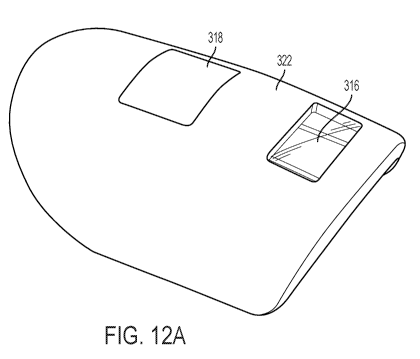
100291 Figure 12 shows a an exploded view of a top layer and a bottom layer
of an
apparatus according to one embodiment of the present invention Figure 12A
shows a top layer
and Figure 12B shows a bottom layer.
[0030] Figures 13A, 13B, 13C, and 13D show an apparatus according to one
embodiment of
the present invention Figure 13A shows a top, perspective view, Figure 13B
shows a side view,
Figure 13C shows a top view, and Figure 13D shows a front view.
4
CA 03010018 2018-06-27
WO 2017/132618 PCT/US2017/015504
[0031] Figures 14A and Figure 14B show a top layer of an apparatus
according to one
embodiment of the present invention. Figure 14A shows a bottom, perspective
view, and Figure
14B shows a bottom view.
[0032] Figure 15 shows views of a bottom layer of an apparatus according to
one
embodiment of the present invention. Figure 15A shows atop, perspective view,
Figure 15B
shows a side view, Figure 15C shows a top view and Figure 15D shows a front
view.
[0033] Figure 16A, Figure 16B, and Figure 16C show a detection layer
according to one
embodiment of the present invention. Figure 16A shows a top, perspective view,
Figure 16B
shows a top view, and Figure 16C shows a cross-sectional view along the line B-
B in Figure
16B
[0034] Figure 17 shows an exploded view of a top layer, an detection layer,
and a bottom
layer of an apparatus according to one embodiment of the present invention.
[0035] Figure 18 shows an embodiment of an apparatus according to one
embodiment of
the present invention Figure 18A shows a side view, Figure 18B shows a cross-
sectional view
along the line A-A of Figure 18A, and Figure 18C shows a front view.
[0036] Figure 19 shows an embodiment of an apparatus according to one
embodiment of
the present invention
100371 Figure 20 shows an embodiment of an apparatus according to one
embodiment of
the present invention
[0038] Figure 21 shows an embodiment of an apparatus according to one
embodiment of
the present invention.
[0039] Figure 22 shows an embodiment of an apparatus comprising an assay
cartridge
according to one embodiment of the present invention.
[0040] Figures 23A and 23B show an apparatus according to one embodiment of
the present
invention. Figure 23A shows a top, perspective view and Figure 23B shows a
bottom,
perspective view.
[00411 Figures 24A and 24B show an apparatus according to one embodiment of
the present
invention. Figure 24A shows a top, perspective view and Figure 24B shows a
bottom,
perspective view.
CA 03010018 2018-06-27
WO 2017/132618 PCT/US2017/015504
[0042] Figure 25 shows a cross sectional view of the detection layer and
the direction of
flow of a liquid through the detection layer according to one embodiment of
the present
invention.
[0043] Figure 26 shows the top view of the detection layer and the
direction of flow of a
liquid through the detection layer according to one embodiment of the present
invention.
100441 Figure 27 shows cut away perspective view of the apparatus and the
direction of
flow of a liquid through the apparatus according to one embodiment of the
present invention.
[0045] Figure 28 shows an exploded cross-sectional view of the detection
layer according to
one embodiment of the present invention.
100461 Figure 29 shows test results of comparative assays and inventive
assays according to
some embodiments described herein
[0047] Figure 30 shows test results of comparative assays and inventive
assays according to
some embodiments described herein.
100481 Figure 31 shows test results of comparative assays and inventive
assays according to
some embodiments described herein.
[0049] Figure 32 shows of test results of comparative assays and inventive
assays according
to some embodiments described herein.
DETAILED DESCRIPTION
[0050] The subject matter of embodiments of the present invention is
described herein with
specificity to meet statutory requirements, but this description is not
necessarily intended to limit
the scope of future claims. The subject matter to be claimed may be embodied
in other ways,
may include different elements or steps, and may be used in conjunction with
other existing or
future technologies. This description should not be interpreted as implying
any particular order
or arrangement among or between various steps or elements except when the
order of individual
steps or arrangement of elements is explicitly described. The illustrative
examples are given to
introduce the reader to the general subject matter discussed herein and not
intended to limit the
scope of the disclosed concepts The following sections describe various
additional
embodiments and examples with reference to the drawings in which like numerals
indicate like
elements and directional description are used to describe illustrative
embodiments but, like the
illustrative embodiments, should not be used to limit the present invention
6
CA 03010018 2018-06-27
WO 2017/132618 PCT/US2017/015504
[0051] Unless indicated to the contrary, the numerical parameters set forth
in the following
specification are approximations that can vary depending upon the desired
properties sought to
be obtained by the present invention. At the very least, and not as an attempt
to limit the
application of the doctrine of equivalents to the scope of the claims, each
numerical parameter
should at least be construed in light of the number of reported significant
digits and by applying
ordinary rounding techniques.
[0052] Notwithstanding that the numerical ranges and parameters setting
forth the broad
scope of the invention are approximations, the numerical values set forth in
the specific
examples are reported as precisely as possible. Any numerical value, however,
inherently
contains certain errors necessarily resulting from the standard deviation
found in their respective
testing measurements. Moreover, all ranges disclosed herein are to be
understood to encompass
any and all subranges subsumed therein. For example, a stated range of "1 to
10" should be
considered to include any and all subranges between (and inclusive of) the
minimum value of 1
and the maximum value of 10; that is, all subranges beginning with a minimum
value of 1 or
more, e.g. 1 to 6.1, and ending with a maximum value of 10 or less, e.g., 5.5
to 10.
[0053] Described herein are methods and a wearable apparatus for detecting
a target
substance. In some embodiments, the methods and apparatus can detect a
targeted compound in
a liquid. In some embodiments, the methods and apparatus can detect a target
substance in a
solid. For example, the methods and apparatus described herein can be used for
real-time
detection of illicit drugs, e.g., amine-containing compounds or drugs,
benzodiazepines, amine-
containing compounds or drugs, analytes, abused narcotics, alcohol, drugs,
date rape drugs, or
other target compounds or analytes As another example, the methods and
apparatus described
herein can be used for real-time detection of certain proteins, sugars, or
allergens, e.g., gluten,
peanut proteins, or lactose. In some embodiments, the methods and apparatus
described herein
can be used for real-time detection of other materials, for example,
pesticides, steroids and their
metabolites, bacteria, pathogens, fungi, poisons, toxins, chemical warfare
agents, environmental
poisons, explosives and the starting materials used to make them, as well as
mixtures of small
molecules, metals, volatile organics, and other targeted compounds.
[0054] In some embodiments, the methods and apparatus described herein can
used for real-
time detection of targeted substances, analytes, or compounds within ketamine,
4-
hydroxybutanoic acid (GHB), ephedrine, methamphetamine, amphetamine,
flunitrazepam, 3,4-
7
CA 03010018 2018-06-27
WO 2017/132618 PCT/US2017/015504
methylenedioxy-methamphetamine (MDMA), also known as ecstasy or molly,
tetrahydrocannabinol (THC), and benzodiazepines such as clonazepam and others,
and many
more. In some embodiments, the methods and apparatus described herein can used
for real-time
detection of targeted substances, analytes, or compounds within foods or
liquids.
[0055] In some examples, the liquid comprises a consumable liquid. For
example, the
consumable liquid can be include beer, cider, energy drinks, flavored drinks,
fruit drinks, liquor
or other alcoholic beverages, milk, milk-containing beverages, soda, sports
drinks, vegetable
drinks, water, wine, and combinations thereof. In some examples, the liquid
comprises a non-
consumable liquid (e.g., blood, non-potable water, organic solvents, potable
water, serum,
treated waste water, untreated waste water, urine, vomit, sweat, tears,
reproductive fluids, other
bodily secretions, or combinations thereof). The liquid can comprise a
solution, a suspension, or
an emulsion. In some examples, the liquid can contain solid particles or ice
suspended therein.
In some examples, the liquid medium can include liquid extract from a solid.
In other cases, the
methods and apparatuses can be used to detect analytes in a solid material,
such as extracting
gluten from bread. In some examples, the methods and apparatuses can be used
to detect
analytes in nutritional supplements, cosmetics, or soil. In further examples,
the methods and
apparatuses can be used to detect the presence of heavy metals.
100561 In some examples, the wearable apparatus may be positioned on the
surface of an
object. In some examples, the apparatus can be positioned, integrated, or
incorporated in an
object. In other examples, the apparatus can be positioned below the surface
of an object. In
some examples, the wearable apparatus may be positioned on a human body.
Wearable as
described herein includes placement on a body or a part of a body as
decoration, protection, or
for some other purpose. Placement may be in direct contact with the body or
indirect contract
with the body. Some examples of items worn include, but are not limited to a
synthetic
fingernails, fingernail decals, rings, bracelets, charms, necklaces, and
lanyards.
100571 In some embodiments, the apparatus is positioned on the body with
adhesive. The
adhesive may be coupled with the bottom surface of the bottom layer to adhere
the apparatus to
the desired surface. Suitable objects include, for example, a fingernail, an
artificial fingernail, a
layer of fingernail polish, a fingernail sticker, a fingernail decal, a
sticker, a decal, a nail wrap, a
mesh nail wrap, a ring, a bracelet, a necklace, a charm, a lanyard, or any
other appropriate
surface or structure. In some embodiments, the apparatus can have a degree of
flexibility to
8
CA 03010018 2018-06-27
WO 2017/132618 PCT/US2017/015504
conform to the intended application of the apparatus. In some embodiments, the
bottom layer
may be flexible to conform to the intended application. In some embodiments,
the detection
layer may be flexible to conform to the intended application. For example,
when the apparatus
may be positioned on an arcuate structure (e.g., a fingernail), the apparatus
can be flexed and
positioned on the arcuate surface of a fingernail.
100581 In some embodiments, the apparatus comprises a thickness ranging
from about 0.1
millimeters (mm) to about 10 mm. In some embodiments, the apparatus comprises
a thickness
ranging from about 1 mm to about 5 mm. In some embodiments, the apparatus can
have a
thickness of about 0.4 mm or less, 0.5 or less, 1 mm or less, 2 mm or less, 3
mm or less, 4 mm or
less, 5 mm or less, 6 mm or less, 7 mm or less, 8 mm or less, 9 mm or less, or
10 mm or less.
100591 In some embodiments, the apparatus can have a length of about 10 mm
to about 25
mm, or from about 10 mm to about 20 mm. In some embodiments, the apparatus can
have a
length of about 10 mm or less, 11 or less, 12 mm or less, 13 mm or less, 14 mm
or les, 15 mm or
less, 16 mm or less, 17 mm or less, 18 mm or less, 19 mm or less, 20 mm or
less, 21 mm or less,
22 mm or less, 23 mm or less, 24 mm or less, 25 mm or less, 26 mm or less, 27
mm or less, 28
mm or less, 29 mm or less, or 30 mm or less.
100601 In some embodiments, the apparatus comprises up to about a width of
about 17 mm,
for example, a width of about 16 mm, about 15.5 mm, about 15 mm, about 14.5
mm, about 14
mm, about 13.5 mm, or about 13 mm. In some examples, the apparatus may have a
width of
about 17 mm to about 13 mm. In some embodiments, the apparatus comprises up to
about a
width of about 4 mm, for example, a width of about 3.8 mm, about 3.6 mm, about
3.4 mm, about
3.2 mm, about 3 mm, about 2.8 mm, or about 2.6 mm. In some embodiments, the
apparatus can
have a width of about 10 mm or less, 11 or less, 12 mm or less, 13 mm or less,
14 mm or less, 15
mm or less, 16 mm or less, 17 mm or less, 18 mm or less, 19 mm or less, 20 mm
or less, 21 mm
or less, 22 mm or less, 23 mm or less, 24 mm or less, 25 mm or less, 26 mm or
less, 27 mm or
less, 28 mm or less, 29 mm or less, or 30 mm or less.
100611 Some embodiments of the apparatus described herein can have a length
of less than
about 25 mm, a width of about 15 mm, and a thickness of about 5 mm. In some
embodiments,
the apparatus described herein can have a length of less than about 20 mm, a
width of about 10
mm, and a thickness of about 2.5 mm.
9
CA 03010018 2018-06-27
WO 2017/132618 PCT/US2017/015504
100621 In some embodiments, the apparatus can be laminated to provide
protection from
external environment without compromising the integrity of the test by
permitting gas
permeability during use. In some embodiments, the apparatus can be waterproof,
or substantially
waterproof, until the apparatus is activated, for example, upon the removal of
a removable layer
or other methods
100631 Certain embodiments described herein provide an apparatus for
detecting the
presence of a compound in a liquid, where the apparatus comprises a detection
layer. In some
embodiments, the detection layer can detect the presence of a target substance
upon being
exposed to a particular medium. In some embodiments, the detection layer can
detect the
presence of target substance or particular compound upon receiving a liquid to
be tested for the
target substance or particular compounds. For example, the detection layer can
be exposed to the
liquid in question and then monitored by a user to determine whether there is
a particular
interaction between the detection layer and the liquid to indicate the
presence of the target
substance. In some embodiments, the target substance may be an amine-
containing compound
or a benzodiazepine. In some embodiments, the target substance may be a
protein or sugar.
[0064] In some embodiments, the detection layer can comprise at least one
of a matrix that
includes a marker, a lateral flow assay, a nanofluidic device, microfluidic
devices,
electrochemical sensors, or a membrane. In some embodiments the detection
layer can operate
by relying on the wicking or drawing of a liquid through the detection layer
by capillary action.
In some embodiments, the detection layer can operate based on a series of
capillary sections that
transport fluids through a plurality of sections. In some embodiments, the
detection layer can
include at least one channel to control and direct the flow of fluid or
particular compounds
through the channels in the layer. In yet some other embodiments, the
detection layer can
include a membrane that separates particular compounds or targeted substances
for detection, for
example by phase separation or other distinguishing indicia.
100651 In some embodiments, the detection layer may be positioned on,
within, and/or
below a surface of an object In some instances, the object may be a
fingernail, an artificial
fingernail, a layer of fingernail polish, a fingernail sticker, a press-on
nail, a fingernail decal, a
sticker, a ring, a bracelet, a necklace, a charm, a lanyard, or other
appropriate surface.
CA 03010018 2018-06-27
WO 2017/132618 PCT/US2017/015504
100661 In some cases, the detection layer further comprises an absorbent.
In some
embodiments, the detection layer may be pre-treated with a desiccant. The
absorbent can include
chromatography paper, silica gel, or alumina.
[0067] In some instances, the detection layer comprises a lateral flow
assay. In some
examples, the lateral flow assay may be multiplexed for testing for the
detection of multiple
compounds. In some embodiments, the apparatus comprising a lateral flow assay
can be
laminated. In some embodiments, the lateral flow assay may be arcuate-shaped.
Lateral flow
assays that can be included within the present apparatus are described and set
forth in a PCT
patent application entitled "Methods and Apparatus for Detecting Compounds in
Liquids,"
applied for by Undercover Colors, Inc. and filed on the same day as the
present application,
which is incorporated by reference in its entirety.
100681 In some embodiments, the detection layer comprises a single layer,
film, or
cartridge. In some embodiments, the detection layers comprises a plurality of
layers or stages
that make up the detection layer. For example, the detection layer can include
a plurality of sub-
layers or stages are configured to absorb a liquid, provide a matrix through
which the liquid can
travel, and provide a reservoir for collecting liquid that travels through the
matrix. In some such
embodiments, the plurality of sub-layers comprise the detection layer. In some
embodiments,
the detection layer can comprise two, three, four, five, six, or seven sub-
layers or more. For
example, the detection layer could include up to twenty sub-layers. In some
embodiments, the
detection layer can be referred to herein as a detection subassembly.
100691 In some embodiments, a sample pad material can be included within
the detection
layer. The sample pad can aid in the wetting of the detection layer. The
sample pad can limit the
amount of liquid that flows into the apparatus. In some embodiments, once the
sample pad is
saturated, the rate of absorption of the liquid can decrease and thus limit
the amount of liquid that
is absorbed, controlling the flow of the liquid into the apparatus.
100701 In some embodiments, the detection layer can be configured to
minimize,
significantly reduce, or substantially eliminate backflow or migration of an
assay component into
the test liquid. This backflow or potential flow of constituents from the
detection layer to the test
liquid may be undesirable, especially for testing of consumable liquids. In
some embodiments,
the potential backflow or reverse flow may comprise the test liquid and
chemical additives from
the detection layer. To address the potential for backflow, in some
embodiments, the detection
11
CA 03010018 2018-06-27
WO 2017/132618 PCT/US2017/015504
layer may further comprise a backflow reduction component. In some
embodiments, the
backflow reduction component may be an untreated pad between the sample port
or opening in
the top layer and the sample pad. The untreated pad may minimize,
significantly reduce, or
substantially eliminate potential flow of material back to the test liquid due
to saturation of the
untreated pad upon introduction of the apparatus into the test liquid. Once
introduced into the
test liquid, the saturated untreated pad may serve as a constraint on backflow
by minimizing the
gradient and motive force of flow from the sample pad to the test liquid. In
some embodiments,
this constraint of flow by the saturated untreated pad may at least
significantly reduce potential
contact between chemical additives or buffers from the detection layer and the
test liquid. In
some embodiments, the constraint of flow by the saturated untreated pad may
help ensure that
essentially none of the chemical additives or buffers from the detection layer
come in contact
with the test liquid. In some embodiments, the design and configuration of the
top layer and
bottom layer may sufficiently encase the detection layer to substantially
prevent backflow to the
test liquid. In this embodiment, the opening for liquid entry is small in
comparison to the size
and surface area of the apparatus. For example, when the wearable apparatus is
introduced to a
liquid, the relatively small opening for liquid presents the only potential
backflow path. The
substantially small size of the opening reduces the potential for back flow.
In some examples,
the backflow reduction component can prevent at least about 70% of the assay
components from
migrating into the liquid sample, for example, at least about 75%õ at least
about 80%, at least
about 85%, at least about 90%, at least about 95%, or at least about 99%.
[0071] In some embodiments, the apparatus comprises a boundary that may
substantially
prevent liquid entrainment at the boundary when the apparatus is fully
submerged. In some
examples, the boundary refers to the peripheral edge of the apparatus or the
perimeter of two
joined edges. In some embodiments, the apparatus comprises a boundary that can
be configured
to substantially prevent liquid entrainment at the boundary when the apparatus
is fully
submerged. The boundary configuration may be achieved by any one of adhesive,
bond, weld,
compressive force, mateable arrangements (stud/anti-stud), electrostatic
interaction, and
magnetic interaction or other methods. In such cases, the full submersion of
the apparatus in a
liquid may have no effect on the detection layer. In some embodiments, the
opening for liquid
entry is small in comparison to the size and surface area of the sealed
apparatus. For example,
when the apparatus is introduced to a liquid, the relatively small opening for
liquid presents the
12
CA 03010018 2018-06-27
WO 2017/132618 PCT/US2017/015504
only path to the detection layer. The substantially small size of the opening
reduces the potential
for flooding of the detection layer.
[0072] In some cases, the area of the opening comprises less than about 30%
of the total
surface area of the top of the apparatus, for example, an area of the opening
of about 29 010, 28 %,
27%, 26%, 25%, 24 'o 23 %, 22%, 21 0/0, 20%, 19%, 18%, 17%, 16%, 15%, 14%,
13%
12 %, 11 9'0, 10 0/0, 9 %, 8 %, 7%, 6 %, 5 %, 4% 3%, 2%, and 1%. In some
examples, the area
of the opening may be about 1% to 30%. In some cases, the area of the opening
comprises less
than about 1% of the total surface area of the top of the apparatus, for
example, an area of the
opening of about 0.9%, 0.8% 0.7% 0.6%, 0.5% 0.4 0.0, 0.3 %, 0.2%, 0.1%. In
some
examples, the area of the opening may be about 5% to 0. 10,0.
[0073] In some embodiments, the absorbent capacity of the wick or absorbent
layer may
also reduce the potential for back flow. For example, the wick or absorbent
layer may have an
absorbent pad capacity substantially greater than the intended sample volume
of the detection
layer; the substantially greater absorbent pad capacity may reduce the
potential for backflow by
ensuring virtually all of the sample and companion detection layer chemicals
are drawn into the
absorbent layer. In some embodiments, the capacity of the absorbent pad may be
50 to 100 13/6
greater than the intended sample volume.
100741 In some embodiments a detection layer comprises a chromatographic
membrane pad
capable of receiving a liquid and allowing for migration of the liquid. In
some instances, the
chromatographic membrane can include an anti-analyte antibody-particle
conjugate at at least a
first location and an analyte-conjugate protein at at least a second location.
In some
embodiments, the chromatographic membrane pad further comprises an anti-
species antibody at
at least a third location. In some instances, the apparatus further comprises
a sample pad capable
of receiving the liquid, and in some cases, the liquid moves from the sample
pad to the
chromatographic membrane. In some embodiments, the liquid moves from the
chromatographic
membrane to a wick or absorbent pad. In some embodiments, the detection layer
further
comprises a conjugate pad. In some embodiments, the sample pad and conjugate
pad may be
connected. In other embodiments, the sample pad and conjugate pad may be
combined. In some
embodiments, at least a portion of the sample pad-conjugate pad overlaps the
chromatographic
membrane pad. In some embodiments, the sample pad-conjugate pad and the
absorbent pad are
not connected. In some embodiments, the absorbent pad can be separated from
the
13
CA 03010018 2018-06-27
WO 2017/132618 PCT/US2017/015504
chromatographic pad with an impermeable membrane, except for the area where
the absorbent
pad overlaps a portion of the chromatographic membrane pad.
[0075] In some embodiments, the detection layer can be configured to direct
flow of a
liquid through the detection layer in a generally horizontal orientation,
e.g., substantially along a
single horizontal plane from a first end of the detection layer to the second
end of the detection
layer. In other embodiments, the detection layer can be configured to direct
flow of a liquid
through the detection layer in a generally vertical orientation, e.g.,
substantially through a
plurality of vertical planes, i.e., from the bottom of the detecting layer to
the top of the detecting
layer. In some embodiments, the detection layer can be configured to split the
flow of a liquid
through the detection layer into multiple paths. In some embodiments, the
liquid may flow along
from a first path to a second curved path that is substantially parallel to
the first path. In some
embodiments, this second path may flow counter-current to the direction of the
first path.
[0076] In some embodiments, the configuration of the detection layer,
specifically the
relationship of the chromatographic membrane pad and the absorbent to each
another may result
in a flow path in a portion of the detection layer being counter-current in
nature. In some
examples, the flow of liquid in the absorbent pad is counter-current to the
direction of flow in the
chromatographic membrane pad. In some embodiments, the configuration of the
detection layer
may allow for the overall length of the detection layer to be substantially
less than a conventional
detection layer that maintains a single-direction flow path throughout the
length of the detection
layer. By overlapping the chromatographic membrane pad and the absorbent pad,
the overall
length of the detection layer can be significantly reduced without reducing
the length of the
overall flow path of the liquid. In some embodiments, the overall length of
the detection layer
may be further reduced by utilizing counter-current flow paths in the
detection layer.
100771 A particular advantage of miniaturization of a lateral flow assay is
timeliness of test
results. For example, a conventional lateral flow assay with an 80 mm long
chromatographic
membrane requires a minimum of 5 minutes to display test results. In contrast,
some
embodiments of the miniaturized assays described herein display test results
much faster. For
example, a 12 mm detection layer comprising a buffer formulation as described
herein requires
only about 30 seconds to display test results. An additional advantage of a
miniaturized lateral
flow assay is reduced test fluid volume. In some examples, a sample volume of
no more than 15
L is required for an apparatus described herein, compared to 80 uL for a
conventional 80 mm
14
CA 03010018 2018-06-27
WO 2017/132618 PCT/US2017/015504
lateral flow assay. In some embodiments, sample volume is less than 40 4, less
than 30 4,
less than 20 4, less than 10 4, or less than 5 [11_,. In some embodiments test
results are
displayed in less than 1 minute, less than 30 seconds, less than 15 seconds,
less than 10 seconds,
or less than 5 seconds.
100781 In some embodiments, the detection layer further comprises a cover
over the
chromatographic membrane. In some instances, the cover may comprise an opening
to permit
gas to escape, or the cover may be gas-permeable. In some cases, the cover may
be an opaque
cover, a tinted cover, a transparent cover, or a translucent cover. In some
embodiments, the
cover defines a stencil pattern, which may comprise an indication such as
"yes", "no", "safe",
"OK", or " ". In some embodiments, the stencil pattern may be placed over the
second
position of the chromatographic membrane. Such a pattern may be helpful to the
user by making
the test results easy to understand.
[00791 The detection layer of certain embodiments described herein can
provide an
indication or signal mechanism to a user as to whether a particular compound
or target substance
may be present. For example, the indication can comprise the appearance of a
colored dot or
region, the absence of any appearance of a colored region, completing lines,
logos, patterns or
symbols, the printing of words, such as "SAFE," "OK," "YES," or "NO,"
checkmarks,
emoticons or symbols such as a "CD," fluorescence, vibration, or sounds In
some embodiments,
the indication can comprise the appearance of a portion of a word or symbol,
for example, the
indication may be the letter "A" of the word "SAFE." In some embodiments, the
detection layer
can provide an indication to a user by electrochemical detection,
polymerization or de-
polymerization in the presence of an analyte, endo- and exothermic reaction
initiation, hydrogel
formation, and a device-aided quantitation, for example with the aid of
smartphone application
or other device. In some embodiments, the presence of an indication can show a
user that a
target substance may be present. In other embodiments, the presence of an
indication can show a
user that a target substance may be absent.
100801 In some embodiments, the detection layer can include an indication
that provides a
portion of a communication to the user, for example, completes a pre-printed
word or symbol.
For example, the detection layer (or other layers, e.g., the top layer) can
include pre-printed or
pre-formed characters such as the letters "S," "F,- and "E." The indication
can comprise the
letter "A" and be aligned to display the indication of "A" between the pre-
formed letters and
CA 03010018 2018-06-27
WO 2017/132618 PCT/US2017/015504
"F- such that the results of the test are displayed in the context of the pre-
printed or preformed
characters as "S A F E"
[0081] In some embodiments, the detection layer can include a plurality of
indication or
signal mechanisms. For example, the detecting layer can include a first
indicator and a second
indicator. In some such embodiments, the first indicator can correspond to a
control, and the
second indicator can correspond to a positive or negative presence of a target
substance. In some
embodiments, the first indicator corresponding to the control can be viewable
by a user showing
the user that the detecting layer was properly and sufficiently disposed to a
liquid. The second
indicator corresponding to the detection of a target substance can be
viewable. In some
embodiments, the first indicator and the second indicator can be complementary
to provide a
single, joined indication. For example, and not to be considered limiting, the
first indicator can
be a horizontal line (" ¨ ") and the second indicator can be a vertical line
(" I ") that intersects
with the first indicator. When both the example first indicator and the
example second indicator
are viewable, the joined indication or character may appear as a "plus" or
cross (" + "). As
another example, and not to be considered limiting, the first indicator can be
the letters "S," "F,"
and "E" and the second indicator can be the letter "A." When both the example
first indicator
and the example second indicator are viewable, the joined indication may
appear as "S A F E."
As one of ordinary skill in the art appreciates, other combinations of the
first indicator and the
second indicator can be utilized.
[0082] In some embodiments, the detection layer comprises a thickness
ranging from about
50 microns to about 1000 microns. In some embodiments, the detection layer
comprises a
thickness ranging from about 200 microns to about 400 microns. In some
embodiments, the
detection layer can have a thickness of about 100 microns or less, 200 microns
or less, 400
microns or less, 600 microns or less, 800 microns or less, or 1000 microns or
less.
[0083] In some embodiments, the detection layer can be subject to different
surface
treatments. For example, the detection layer can be subject to a ozonation
treatment. In some
embodiments, the detection layer can be subject to one or more surface
treatments that can
increase the hydrophilicity of the layer, and can in some cases, improve
wetting properties of the
layer. In some embodiments, the surface treatment can aid in prevent air
pockets or bubbles
from forming at an opening when the apparatus is exposed to a liquid.
16
CA 03010018 2018-06-27
WO 2017/132618 PC T/US2017/015504
[0084] In some embodiments, the detection layer can be configured to detect
the presence of
a plurality of targeted substances. For example, the detection layer can be
configured to detect
multiple illicit drugs on one particular detection layer. In some embodiments,
the detection layer
can be physically divided to permit the detecting of multiple drugs without
the inferring with the
detection of another drug. As another example, a detection layer can be
multiplexed with certain
components to test for multiple drugs on a single detection layer. In some
embodiments, the
apparatus can include a plurality of discrete, physical sections positioned
adjacent to each other
to make up a single detection layer. For example, a plurality of matrices can
be positioned side
by side with each matrix configured to test for the presence of a different
compound in a liquid.
100851 In some embodiments, the apparatus comprising a detection layer can
also include at
least one additional layer. In some embodiments, the apparatus can include at
least one of a top
layer, a bottom layer, and a removable layer. In some embodiments, the
apparatus can include
any combination of layers described herein
100861 The apparatus described herein can also include a top layer
positioned on a top
surface of a detection layer. In some embodiments, the top layer can be
coupled to the detection
layer using an adhesive. In some embodiments, the adhesive can comprise
acrylate copolymer
microspheres, acrylic and methacrylic ester homo-or copolymers, butyl rubber
based systems,
silicones, urethanes, vinyl esters and amides, olefin copolymer materials, di-
alkyl fumarates,
natural or synthetic rubbers, and the like, including hot-melt adhesives.
[0087] Coupling as described herein may be direct or indirect. The layers
may be coupled
by adhesive, bond, weld, compressive force, mateable surfaces (stud / anti-
stud), electrostatic
interaction, magnetic interaction, otherwise covering a surface, or other
methods known to those
of skill in the art.
[0088] In other embodiments, the top layer can be coupled to the detection
layer by heat
sealing at least a portion of the respective layers, by ultrasonic welding the
two layers, through
the use of ultraviolet radiation curable adhesive, or through the use of
pressure-sensitive
adhesives. In some embodiments, other suitable binding material or methods
known to those of
skill in the art can be used to couple the detection layer to the top layer.
100891 In some embodiments, the top layer defines an opening through which
at least a
portion the detection layer may be exposed. In some embodiments, the opening
provides a
channel through which the detection layer can absorb a liquid to be tested. In
some
17
CA 03010018 2018-06-27
WO 2017/132618 PCT/US2017/015504
embodiments, the opening can be positioned at an end or boundary edge of the
top layer, for
example at a tip, to provide a channel through which the detection layer can
absorb a liquid to be
tested.
[0090] In other embodiments, the detection layer can include an opening at
an end or
boundary of the detection layer, for example at a tip, to provide a channel
through which the
detection layer can absorb a liquid to be tested. The end or boundary' of the
detection layer can
be positioned in proximity to an end or boundary of the apparatus.
[0091] The top layer can be an opaque cover, a tinted cover, a transparent
cover, or a
translucent cover. Optionally, the top layer can include one or more
perforations. These
perforations can allow for the escape of gaseous materials during the use of
the apparatus. In
some embodiments, the top layer may be a gas permeable membrane. As fluid is
absorbed by
the detection layer, the gas or air within the test may be displaced and
escape or venting of the
displaced gas may be needed.
100921 In examples where the top layer may be opaque, tinted, or
translucent, the top layer
can optionally include one or more transparent windows on the top layer. In
some embodiments,
the transparent window can be aligned and positioned on the detection layer
such that the
indication or signal mechanism of the detection layer can be visible through
the transparent
window. Window may include opening, aperture, void, lens, or the like. In some
embodiments,
the transparent window of the top layer can be shaped as certain words, such
as "SAFE," "OK,"
"YES," or "NO," checkmarks, completing lines, logos, patterns or symbols,
emoticons or
symbols such as a " ," that can provide the results of the test to a user.
[0093] In some embodiments, the top layer comprises a laminate layer. In
some
embodiments, the top layer comprises a thin film. The top layer can be
constructed of different
materials. In some embodiments, the thin film comprises at least one of a
metal material,
polymeric material, ceramic material, inorganic material, and other suitable
material. In some
embodiments, the top layer can comprise one or more of ABS (acrylonitrile
butadiene styrene),
ABS + PC (ABS + polycarbonate alloy), acetal (POM) (polyoxymethylene), LCP
(liquid crystal
polymer), Nylon 6-PA (polyamide), Nylon 6/6-PA (polyamide), Nylon 11-PA
(polyamide), PBT
polyester (polybutylene terepthalate), PC (polycarbonate), PEI
(polyetherimid), PE
(polyethylene), LDPE (low density polyethylene), HDPE (high density
polyethylene), PET
polyester (polyethylene terepthalate), PP (polypropylene), PPA
(polyphthalamide), PPS
18
CA 03010018 2018-06-27
WO 2017/132618 PCT/US2017/015504
(polyphenylene sulfide), PS (polystyrene crystal), HIPS (high impact
polystyrene), PSU
(polysulfone), PVC (polyvinylchloride), PVDF (polyvinylidene fluoride), SAN
(styrene
acrylonitrile), TPE (thermoplastic elastomer), TPU (thermoplastic polyurethane
elastomer),
copolymers thereof, metal foils, and mixtures thereof. The polymeric materials
may be
thermosetting or thermoplastic. These polymers typically have a tensile
strength in the range of
1,000-50,000 psi; a flexural modulus of 5,000 to 5,000,000 psi; an impact
strength of 0.1 ft-lb/in
notched Izod to 30 ft-lb/in notched Izod.
[0094] In some embodiments, the top layer can be subject to different
surface treatments.
For example, the top layer can be subject to a ozonation treatment. In some
embodiments, the
top layer can be subject to one or more surface treatments that can increase
the hydrophilicity of
the layer, and can in some cases, improve wetting properties of the layer. In
some embodiments,
the surface treatment can aid in prevent air pockets or bubbles from forming
at an opening when
the apparatus is exposed to a liquid.
100951 In some embodiments, the top layer comprises a thickness ranging
from about 10
microns to about 1000 microns. In some embodiments, the top layer comprises a
thickness
ranging from about 200 microns to about 400 microns. In some embodiments, the
top layer can
have a thickness of about 100 microns or less, 200 microns or less, 400
microns or less, 600
microns or less, 800 microns or less, or 1000 microns or less.
[0096] In some embodiments, the apparatus has sufficient structural
strength to resist
structural change from an external force that would damage the apparatus to
the extent that the
apparatus did not function to achieve an intended result. In some embodiments,
the top layer
provides the structural strength of the apparatus, or substantially all of the
structural strength of
the apparatus. In some embodiments, a bottom layer (as described below)
provides the structural
strength of the apparatus, or substantially all of the structural strength of
the apparatus. In some
embodiments, the top layer and the bottom layer provide the structural
strength of the apparatus.
Structural changes that could damage the apparatus, depending on the nature of
the apparatus,
may include deformation, collapse, creasing, puncture and the like. In some
embodiments, the
apparatus may have sufficient structural strength to resist deformation,
collapse, creasing, or
puncture. By way of non-limiting examples, a structural change may: restrict
liquid flow; cause
the channel liquid to flow in unintended ways, cause unwanted accumulation of
the detecting
19
CA 03010018 2018-06-27
WO 2017/132618 PCT/US2017/015504
substance; or cause incorrect results to occur. The type of structural change
that may damage the
apparatus may depend, at least in part, on apparatus design.
100971 In some embodiments, the structural strength of the apparatus may be
sufficient to
sustain an external axial compressive force of >0.1 Newtons and a
perpendicular compressive
force of >40 Newtons without impacting the ability of the apparatus to detect
the presence of a
targeted substance. In some embodiments, the apparatus may sustain an external
axial
compressive force of >0.25 Newtons and a perpendicular compressive force of
>30 Newtons
without impacting the ability of the apparatus to detect the presence of a
targeted substance. In
some embodiments, the apparatus may sustain an external axial compressive
force of >0.5
Newtons and a perpendicular compressive force of >20 Newtons without impacting
the ability of
the apparatus to detect the presence of a targeted substance. In some
embodiments, the apparatus
may sustain an external axial compressive force of >20 Newtons and a
perpendicular
compressive force of >35 Newtons without impacting the ability of the
apparatus to detect the
presence of a targeted substance. In some embodiments, the apparatus may
sustain an external
axial compressive force of >60 Newtons and a perpendicular compressive force
of >100
Newtons without impacting the ability of the apparatus to detect the presence
of a targeted
substance.
100981 In some embodiments, the apparatus may sustain an external
perpendicular force of
1000 Newtons without impacting the ability of the apparatus to detect the
presence of a targeted
substance, In some embodiments, the apparatus may sustain an external force of
2500 Newtons
without impacting the ability of the apparatus to detect the presence of a
targeted substance.
100991 The apparatus described herein can also include a bottom layer
coupled to a bottom
surface of a detection layer. In some embodiments, the bottom layer can be
coupled to the
detection layer using an adhesive. In some embodiments, the adhesive can
comprise acrylate
copolymer microspheres, acrylic and methacrylic ester homo-or copolymers,
butyl rubber based
systems, silicones, urethanes, vinyl esters and amides, olefin copolymer
materials, di-alkyl
fumarates, natural or synthetic rubbers, and the like, including hot-melt
adhesives.
101001 In other embodiments, the bottom layer can be coupled to the
detection layer by heat
sealing at least a portion of the respective layers, by ultrasonic welding the
two layers, or through
the use of pressure-sensitive adhesives. In some embodiments, other suitable
binding material or
methods known to those of skill in the art can be used to couple the detection
layer to the bottom
CA 03010018 2018-06-27
WO 2017/132618 PCT/US2017/015504
layer. In some embodiments, the bottom layer defines an opening through which
the detection
layer may be exposed. In some embodiments, the opening provides a channel
through which the
detection layer can absorb a liquid to be tested. In some embodiments, the
opening can be
positioned at an end or boundary edge of the bottom layer, for example at a
tip, to provide a
channel through which the detection layer can absorb a liquid to be tested.
[01011 In some embodiments where the apparatus may be positioned on an
object, the
bottom layer can be coupled to the object with an adhesive. For example, if
the apparatus is
positioned on a fingernail, the adhesive can comprise an FDA-approved adhesive
for skin
contact, known to those of ordinary skill in the art.
101021 In some embodiments, the bottom layer comprises a structure of
sufficient rigidity to
protect the detection layer from being damaged when used or applied to a
desired surface, for
example, on a finger nail. In some embodiments, the bottom layer can function
as an insulating
layer that protects the detection layer from the environment in which the
apparatus may be
employed. For example, the bottom layer can be impermeable to certain fluids
or materials, such
as those present in fingernail polish. In some such embodiments, the bottom
layer can provide a
layer that eliminates or minimizes any undesired interactions between the
detection layer and the
external environment, for example, the fingernail polish applied to a user's
fingernail.
101031 In some embodiments, the bottom layer comprises a laminate layer. In
some
embodiments, the bottom layer comprises a thin film. The bottom layer can be
constructed of
different materials. In some embodiments, the thin film comprises at least one
of a metal
material, polymeric material, ceramic material, inorganic material, and other
suitable material.
In some embodiments, the bottom layer can comprise one or more of ABS
(acrylonitrile
butadiene styrene), ABS + PC (ABS + polycarbonate Alloy), acetal (POM)
(polyoxymethylene),
LCP (liquid crystal polymer), Nylon 6-PA (polyamide), Nylon 6/6-PA
(polyamide), Nylon 11-
PA (polyamide), PBT polyester (polybutylene terepthalate), PC (polycarbonate),
PEI
(polyetherimid), PE (polyethylene), LDPE (low density polyethylene), HDPE
(high density
polyethylene), PET polyester (polyethylene terepthalate), PP (polypropylene),
PPA
(polyphthalamide), PPS (polyphenylene sulfide), PS (polystyrene crystal), HIPS
(high impact
polystyrene), PSU (polysulfone), PVC (polyvinylchloride), PVDF (polyvinylidene
fluoride),
SAN (styrene acrylonitrile), TPE (thermoplastic elastomer), TPU (thermoplastic
polyurethane
elastomer), copolymers thereof, metal foils, and mixtures thereof.
21
CA 03010018 2018-06-27
WO 2017/132618 PCT/US2017/015504
101041 In some embodiments, the bottom layer can be subject to different
surface
treatments. For example, the bottom layer can be subject to a ozonation
treatment. In some
embodiments, the bottom layer can be subject to one or more surface treatments
that can increase
the hydrophilicity of the layer, and can in some cases, improve wetting
properties of the layer. In
some embodiments, the surface treatment can aid in prevent air pockets or
bubbles from forming
at an opening when the apparatus is exposed to a liquid.
101051 In some embodiments, the bottom layer comprises a thickness ranging
from about 50
microns to about 1000 microns. In some embodiments, the bottom layer comprises
a thickness
ranging from about 200 microns to about 400 microns. In some embodiments, the
bottom layer
can have a thickness of about 100 microns or less, 200 microns or less, 400
microns or less, 600
microns or less, 800 microns or less, or 1000 microns or less.
[0106] The apparatus described herein can also include an activation means.
In some
embodiments, the activation means may be a removable layer. The removable
layer can provide
a layer that provides an external barrier on the apparatus, and then may be
removed prior to use
of the apparatus when checking for the presence of a particular substance or
compound.
[0107] In some embodiments, the removable layer can be coupled to a top
surface of a
detection layer. In some embodiments, the removable layer can be coupled
directly to the top
surface of the detection layer. In other embodiments, the removable layer can
be coupled
indirectly to the top surface of the detection layer, for example, coupled to
a top layer that may
be positioned between the removable layer and the detection layer. In some
embodiments, the
removable layer can be removed from the apparatus to expose at least a portion
of the detection
layer for use to detect the presence of a target compound in a liquid. For
example, in some
embodiments, the removable layer can be peeled off exposing the remaining
portion of the
apparatus, and then inserted into a liquid. In other embodiments, the
removable layer can be
removed by sliding the removable layer and in turn exposing the remaining
portion of the
apparatus. In other embodiments, the removable layer can be removed by scratch-
off type
activation, for example, a wax layer that can be scratched-off to expose the
remaining portion of
the apparatus. In other embodiments, the removable layer can be dissolvable
layer that can be
removed by exposing the layer to a stimulus. In yet other embodiments, the
removable layer can
be removed by breaking off or snapping off a portion of the removable layer
and in turn
22
CA 03010018 2018-06-27
WO 2017/132618 PCT/US2017/015504
exposing the remaining portion of the apparatus, for example, breaking off a
portion of a drink
stirrer to expose and activate the remaining portion of the apparatus.
[0108] In some embodiments, the removable layer comprises a peelable
adhesive. In other
embodiments, the removable layer comprises a layer of nail polish configured
to be peeled off of
the apparatus In some embodiments, the removable layer can be coupled to the
detection layer
or top layer using an adhesive. In some embodiments, the adhesive can comprise
acrylate
copolymer microspheres, acrylic and methacrylic ester homo-or copolymers,
butyl rubber based
systems, silicones, urethanes, vinyl esters and amides, olefin copolymer
materials, di-alkyl
fumarates, natural or synthetic rubbers, and the like, including hot-melt
adhesives.
101091 In other embodiments, the removable layer can be coupled to the
detection layer or
top layer by heat sealing at least a portion of the respective layers, by
ultrasonic welding the two
layers, or through the use of pressure-sensitive adhesives. In some
embodiments, other suitable
binding material or methods known to those of skill in the art can be used to
couple the detection
layer to the bottom layer.
101101 In some embodiments, the strength of adhesion between the removable
layer and for
example, the top layer, may be less than the strength of adhesion between for
example the top
layer and the detection layer or the bottom layer and the detection layer. The
relative lower
strength of adhesion coupling the removable layer in the apparatus (as
compared to adhesion
strength between the other layers) can permit the removal of the removable
layer without
decoupling the remaining layers of the apparatus,
[0111] In some embodiments, the removable layer can be coupled to the top
layer by a
complementary tongue and groove coupling. In some such embodiments, the
removable layer
can be removed by sliding the removable layer in a specific direction, i.e.,
along the plane of the
groove, to permit the removal of the removable layer and exposing of the
detection layer.
101121 In some embodiments, the removable layer comprises a structure of
sufficient
rigidity to protect the detection layer or other layers from being damaged
when not in use, for
example, on a finger nail. In some embodiments, the removable layer can
function as an
insulating or barrier layer that protects the detection layer from the
external environment prior to
the apparatus being employed. For example, the removable layer can be
impermeable to certain
fluids or materials, such as fingernail polish. In some such embodiments, the
removable layer
can provide a layer that eliminates or minimizes any undesired interactions
between the detection
23
CA 03010018 2018-06-27
WO 2017/132618 PCT/US2017/015504
layer and the external environment. In some embodiments, the removable layer
may be
waterproof. In some such embodiments, the removable layer can cause the
apparatus to be
substantially waterproof. Upon removal of the removable layer, the apparatus
can be activated
and available for use, for example, exposed to a liquid to be tested.
[0113] In some embodiments, the removable layer provides a surface upon
which the
external appearance of the apparatus can be modified or customized. For
example, the
removable layer can provide a surface upon which a manufacturer can customize
the appearance
with different designs, decals, logos, colors, or other indicia. As another
example, the removable
layer can provide a surface upon which a user can apply fingernail polish.
[0114] In some embodiments, the removable layer comprises a thin film. The
removable
layer can be constructed of different materials. In some embodiments, the thin
film may be
comprised at least one of a metal material, polymeric material, ceramic
material, inorganic
material, and other suitable material. In some embodiments, the removable
layer can comprise
polyethylene, polyethylene terephthal ate, polyvinyl chloride, polyurethane,
polypropylene,
copolymers thereof, metal foils, and mixtures thereof. In some embodiments,
the removable
layer can be subject to different surface treatments. For example, the
removable layer can be
subject to a ozonation treatment. In some embodiments, the removable layer can
be subject to
one or more surface treatments that can increase the hydrophilicity of the
layer, and can in some
cases, improve wetting properties of the layer. In some embodiments, the
surface treatment can
aid in prevent air pockets or bubbles from forming at an opening when the
apparatus is exposed
to a liquid.
[0115] In some embodiments, the removable layer comprises a thickness
ranging from
about 50 microns to about 1000 microns. In some embodiments, the removable
layer comprises
a thickness ranging from about 200 microns to about 400 microns. In some
embodiments, the
removable layer can have a thickness of about 100 microns or less, 200 microns
or less, 400
microns or less, 600 microns or less, 800 microns or less, or 1000 microns or
less.
[0116] In some embodiments, the apparatus can additionally include a layer
comprising an
opening. The layer can define a particular opening to facilitate the analysis
of the test results.
For example, the opening can be configured in words, such as "SAFE," -OK,"
"YES," or "NO,"
checkmarks, completing lines, logos, patterns or symbols, emoticons or symbols
such as a
Upon the movement of a marker or other indicator to the region of layer
comprising an opening,
24
CA 03010018 2018-06-27
WO 2017/132618 PCT/US2017/015504
the indicator or color dye can be visible to a user through the opening
facilitating the reading of
the test results. In some embodiments, the layer can be a discrete layer. In
other embodiments,
the layer can be integrated within other layers, for example, a top layer.
[0117] In some embodiments, the apparatus can additionally include a layer
comprising a
defined pattern of reagents positioned in a certain manner to facilitate the
analysis of the test
results. For example, the pattern of reagents can be configured in words, such
as "SAFE,"
"OK," "YES," or "NO," checkmarks, completing lines, logos, patterns or
symbols, emoticons or
symbols such as a "0." Upon the movement of a marker or other indicator to the
region of
layer comprising the pattern of reagents, the marker or other indicator can
interact with the
reagent and in turn display the pattern. When the pattern is displayed, a user
can more easily
analyze the results of the apparatus. In some embodiments, the layer can be a
discrete layer. In
other embodiments, the layer can be integrated within other layers, for
example, a top layer.
[0118] In some embodiments, the apparatus can be positioned on the surface
of an object.
In some examples, the apparatus can be positioned within an object. In other
examples, the
apparatus can be positioned below the surface of an object. Suitable objects
include, for
example, a fingernail, an artificial fingernail, a layer of fingernail polish,
a fingernail sticker, a
fingernail decal, a sticker, a decal, a nail decal, a mesh nail wrap, a ring,
a bracelet, a necklace, a
charm, a lanyard, or any other appropriate surface. Other appropriate surfaces
include items that
could easily and discreetly be brought into contact with a suspect liquid,
providing an improved
degree of personal security for the liquid consumer.
101191 Embodiments of an apparatus and multi-layer detection system are
illustrated in the
figures. As will be understood, the illustrated embodiments are provided as a
way to illustrate
the features and advantages of the present invention and should not be read as
limiting the
present invention to any particular examples. Further, the use of top, bottom
and side in the
following description of the figures is to aid understanding and should not be
read as a
geographic/orientation limitation of embodiments of the present invention.
101201 Turning to the figures, Figure 1 shows an exploded view of apparatus
1 comprising a
removable layer 11, a top layer 12, detection layer 13, and a bottom layer 14.
Figure 2 shows
apparatus 1 in a partially assembled configuration with the removable layer 11
not being coupled
to the top layer 12.
CA 03010018 2018-06-27
WO 2017/132618 PCT/US2017/015504
101211 In Figure 1, the detection layer 13 shows the direction in which a
liquid travels upon
exposing the apparatus to a liquid for testing. The top layer 12 comprises a
window 16 at a first
location and an opening 17 at a second location. The window 16 can be aligned
with the
detection layer 13 such that when the test is complete an indicator 15 can be
visible to a user.
For example, if the apparatus does not detect the presence of a certain
compound in a liquid, an
indication can be visible in the window 16. Window 16 is in the shape of the
letters "OK," but
other shapes of window 16 can be included in top layer 12. Opening 17 of the
top layer can
provide an opening through which liquid or other medium can travel to the
detection layer 13 for
testing.
101221 Figures 3A to 3C show top views of the apparatus before and after
different tests to
detect a targeted substance. Figure 3A shows the apparatus prior to testing.
In Figure 3B, the
apparatus has been exposed to a liquid where the detection layer absorbs the
liquid in question,
and then displays the results of the test where the indicator has traveled the
length of the
detection layer resulting in the color being shown through the window 16. The
indication shown
in Figure 3B corresponds to a test where the target substance is not present.
In Figure 3C, the
apparatus has been exposed to a liquid where the detection layer absorbs the
liquid in question,
and then displays the results of the test where the indicator did not travel
the length of the
detection layer. The indication shown in Figure 3C corresponds to a test where
the target
substance is present in the liquid.
101231 In some embodiments like that shown in Figure 5, the detection layer
13 comprises a
physical break that defines an optional slit 18. The slit 18 can divide the
detection layer into two
halves, for example, to be used to detect two target substances. The top layer
12 comprises a
window 26 at a first location and a window 27 at a second location. The window
26 and window
27 can be aligned with the position of an indicator (not shown) of the
detection layer 13. For
example, if the apparatus does not detect the presence of a certain compound
in a liquid, an
indication can be visible in the window 26. In some embodiments, an optional
layer 22 can be
applied on the removable layer 11, such as finger nail polish, a sticker, a
decal, or other
materials. Figure 5 also shows an optional window 23 positioned in the bottom
layer 14. In
some embodiments, the optional window 23 can be aligned with the position of
an indicator (not
shown) of the detection layer 13. The optional window 23 can positioned at
different regions of
the bottom layer 14, for example, at the opposite end of the bottom layer 14.
26
CA 03010018 2018-06-27
WO 2017/132618 PCT/US2017/015504
101241 Figure 6 shows a top view of a detection layer 200 according to one
embodiment
described herein. The detection layer 200 comprises an absorbent pad 260
(sometimes referred
to as a wick) and a test strip 280. The test strip 280 comprises sample pad-
conjugate pad 250
and a chromatographic membrane pad 230. The sample pad-conjugate pad 250
contacts the
proximal end of chromatographic membrane pad 232. The sample pad-conjugate pad
250 may
be separated from the absorbent pad 260. Liquid absorbed into the sample-
conjugate pad 250
may flow to a distal end of the chromatographic membrane pad 234 and then flow
outwardly
through absorbent pad 260. The distal end of the chromatographic membrane 234
overlaps a
portion of the u-shaped absorbent pad 260.
101251 Figure 7 shows a cross sectional view of a detection layer 200 along
the plane 7-7
shown in Figure 6. Detection layer 200 comprises a sample pad-conjugate pad
250, a
chromatographic membrane pad 230, and an absorbent pad 260. The sample pad-
conjugate pad
250 overlaps with the proximal end of the chromatographic membrane pad 232 at
conjugate area
254. Liquid absorbed into the sample-conjugate pad 250 may flow to a proximal
end 232 of the
chromatographic membrane pad 230 toward the distal end 234 of the
chromatographic
membrane pad 230. The distal end of the chromatographic membrane 234 overlaps
a portion of
the u-shaped absorbent pad 260. The absorbent pad 260 may absorb liquid from
the
chromatographic membrane pad 230 during use. Optionally, the detection layer
200 may have a
top layer 270. In some embodiments, the top layer 270 may be adhesive. In some
embodiments,
the top layer 270 may be transparent. In some embodiments, the combined sample
pad-
conjugate pad 250 has a sample area 252 and a conjugate area 254 that do not
overlap.
101261 In some embodiments, the detection layer comprises a matrix. The
matrix can
include a marker. The marker can be included in the matrix by contacting the
matrix with a
composition comprising a marker. A marker refers to a compound, substance, or
antibody
coupled to a particular substance that can facilitate the detection of a
target substance. For
example, in some embodiments, the marker can include an antibody coupled to
latex or polymer
microbeads or gold nanoparticles. In some embodiments, the marker comprises
carboxyfluorescein, 2,7-dichlorofluorescein, Eosin B, Eosin Y, erythrosine,
fluorescein,
fluorescein amidite, fluorescein isocyanate, merbromin, aptamers, antibodies,
phloxine B, Rose
Bengal, derivatives and salts thereof, or combinations thereof. In other
embodiments, particles
27
CA 03010018 2018-06-27
WO 2017/132618 PCT/US2017/015504
can be used as markers. The particle may be any colored nanoparticle such as
gold and/or dye-
infused polymer microbeads.
[0127] In some embodiments, the apparatus comprises a marker having the
following
formula:
R9
R8 R1
R7 COOR11
R3 R6
R2 R5
X 0
R1 R4
or a salt thereof, where RI, R2, 12.3, R4, R5, R6, R8, R9, and RI0 are each
independently selected
from the group consisting of hydrogen, halogen, hydroxyl, nitro, cyano,
trifluoromethyl,
substituted or unsubstituted amino, substituted or unsubstituted alkyl,
substituted or unsubstituted
alkenyl, substituted or unsubstituted alkynyl, substituted or unsubstituted
heteroalkyl, substituted
or unsubstituted heteroalkenyl, substituted or unsubstituted heteroalkynyl,
substituted or
unsubstituted cycloalkyl, substituted or unsubstituted cycloalkenyl,
substituted or unsubstituted
cycloalkynyl, substituted or unsubstituted aryl, substituted or unsubstituted
heteroaryl,
substituted or unsubstituted carbonyl, substituted or unsubstituted carboxyl,
substituted or
unsubstituted thio, and substituted or unsubstituted sulfonyl; RI I is
hydrogen or substituted or
unsubstituted alkyl; X is hydroxyl or substituted or unsubstituted amino; and
Y is 0 or NRI2,
wherein R12 is hydrogen or substituted or unsubstituted alkyl. In some such
embodiments, the
marker has the following formula:
R9
R8 R1
R7 COOR11
R3 R6
R2 R5
HO 0 0
R1 R4
[01281 In other embodiments, the marker has the following formula:
28
CA 03010018 2018-06-27
WO 2017/132618 PCT/US2017/015504
R9
R8 Rio
R7 C00- M+
R3 R6
R2 R5
+MO 0 0
R1 R4
wherein M is a cation. In some such embodiments, M- is selected from the group
consisting of
Na-, K-, Li, Cs, Rb+, Ag-, Au-, Cu-, Fr-, NIV, NR4--, and NRIR2R1+.
101291 In other embodiments, the marker has the following formula:
0
0
R2 R4
X 0
R1 R3
or a salt thereof, where RI, R2, R3, R4, and Rs are each independently
selected from the group
consisting of hydrogen, halogen, hydroxyl, nitro, cyano, trifluoromethyl,
substituted or
unsubstituted amino, substituted or unsubstituted alkyl, substituted or
unsubstituted alkenyl,
substituted or unsubstituted alkynyl, substituted or unsubstituted
heteroalkyl, substituted or
unsubstituted heteroalkenyl, substituted or unsubstituted heteroalkynyl,
substituted or
unsubstituted cycloalkyl, substituted or unsubstituted cycloalkenyl,
substituted or unsubstituted
cycloalkynyl, substituted or unsubstituted aryl, substituted or unsubstituted
heteroaryl,
substituted or unsubstituted carbonyl, substituted or unsubstituted carboxyl,
substituted or
unsubstituted thio, and substituted or unsubstituted sulfonyl, and X and Y are
each independently
hydroxyl or substituted or unsubstituted amino.
101301 In some embodiments, the marker can be included in the matrix by
contacting the
matrix with a composition comprising a marker. The marker can be present on
the matrix at at
least a first location. For example, the marker composition can be loaded onto
the matrix at the
location 50 in the Figure 4A. The amount of marker composition that can be
loaded onto the
matrix can be quantified by the size of the mark applied to the matrix. The
amount of marker
composition can be a quantity that is large enough to be visualized by the
human eye. For
29
CA 03010018 2018-06-27
WO 2017/132618 PCT/US2017/01550-1
example, the marker composition can be applied to the matrix as a dot of
diameter in a range up
to about 10 mm (e.g., from about 1 mm to about 10 mm or from about 1 mm to
about 5 mm).
The size of the applied composition can have a diameter of about 1 mm or less,
2 mm or less, 3
mm or less, 4 mm or less, 5 mm or less, 6 mm or less, 7 mm or less, 8 mm or
less, 9 mm or less,
or 10 mm or less. In some embodiments, the marker composition can be applied
as a line in a
range up to about 10 mm (e.g., from about 1 mm to about 10 mm or from about 1
mm to about 5
mm). The size of the applied composition can have a height of about 1 mm or
less, 2 mm or less,
3 mm or less, 4 mm or less, 5 mm or less, 6 mm or less, 7 mm or less, 8 mm or
less, 9 mm or
less, or 10 mm or less.
101311 In some embodiments, an apparatus for detecting the presence of a
targeted
substance comprises a length of less than about 25 millimeters, a width of
about 15 millimeters,
and a thickness of about 5 millimeters. In some embodiments the apparatus may
be configured
to detect a targeted substance present in a liquid when the targeted substance
may be present in a
concentration less than about 5 milligrams per milliliter. In some
embodiments, the apparatus
can detect the presence of the targeted substance upon being exposed to the
targeted substance
for less than ten seconds. In some embodiments, the apparatus can provide
indication of the
presence of the targeted substance in less than 5 minutes after being exposed
to the liquid.
101321 In some embodiments, the detection layers of the apparatuses
according to the
description herein comprise a matrix. The matrix can comprise one or more
polymers. In certain
embodiments, the one or more polymers comprise polysaccharides. Suitable
polysaccharides for
use in the matrix include agar, agarose, alginate, carrageenan, cellulose,
chitosan, dextran,
konjac, and mixtures thereof. In some embodiments, the matrix includes
cellulose or cellulose
derivatives, including surface-functional ized cellulose. Exemplary agarose
polymers include, for
example, carboxymethyl agarose, diethylaminoethyl agarose, and like
derivatives. Optionally,
the agarose polymers for use in the matrix are commercially available from
Pharmacia Fine
Chemicals, Inc. (Piscataway, N.J.). Exemplary cellulose polymers include, for
example, cellulose
esters (e.g., cellulose acetate, cellulose acetate butyrate, cellulose acetate
propionate),
carboxymethyl cellulose, diethylaminoethyl (DEAE) cellulose, nitrocellulose,
phosphocellulose,
quaternary ammonium substituted cellulose, and sulfoxyethyl cellulose.
Optionally, the
cellulose polymers for use in the matrix are commercially available from
Whatman Co.
(Whatman Paper Co., Ltd., Maidstone, England) or BioRad Corp. (Richmond,
California).
CA 03010018 2018-06-27
WO 2017/132618 PCT/US2017/015504
101331 The matrix can further include an absorbent. In some embodiments,
the matrix can
comprise a plurality of absorbents. For example, the absorbent can include
chromatography
paper, filter paper, and other materials typically used for chromatography,
such as for paper
chromatography or thin layer chromatography (TLC). The chromatography paper
and filter
paper can be qualitative or quantitative filter paper, such as the
chromatography paper and filter
paper commercially available from Whatman Co. (Whatman Paper Co., Ltd.,
Maidstone,
England).
101341 Optionally, the absorbent comprises silica gel, alumina, high
performance thin layer
chromatography (HPTLC) silica gel, polysilicic acid, aluminum oxide,
cellulose, polyamide,
reversed phase silica Gel C2 (dimethyl bonded), reversed phase silica gel C2
(ethyl bonded),
reversed phase silica gel C8 (octyl bonded), reversed phase silica gel C18
(octadecyl bonded),
acetylated cellulose, silica gel modified with amino groups, silica gel
modified with cyano
groups, Kieselghur impregnated with hydrocarbons, anionic and cationic anion
exchange resins,
diethylaminoethyl cellulose, and mixtures of the listed sorbents. The
absorbent can be
immobilized on an inert surface.
101351 Optionally, the matrix can be pre-treated with a desiccant to
integrate the desiccant
into the matrix. The desiccant can be any desiccant as known to those of skill
in the art,
including, but not limited to, molecular sieves, silica gels, clays, synthetic
polymers, and
starches. For example, suitable desiccants include alumina, bauxite, anhydrous
calcium sulfate,
water-absorbing clays, silica gel, zeolite, and mixtures thereof.
101361 Optionally, the matrix can be pre-treated with a buffering agent.
The buffering agent
can be, for example, acetic acid and a conjugate base thereof, citric acid and
a conjugate base
thereof, dibasic sodium phosphate, polyelectrolyte polymers, potassium
hydrogen phthalate,
sodium hydroxide, sodium phosphate, and combinations thereof. The matrix can
be pre-treated
with a buffering agent such that the matrix may be buffered at a pH ranging
from about 3 to
about 8 (e.g., from about 4 to about 6 or from about 4.5 to about 5.5). For
example, the buffering
agent can be added to the composition to provide a pH of about 3, about 3.5,
about 4, about 4.5,
about 5, about 5.5, about 6, about 6.5, about 7, about 7.5, about 8, about
8.5, or about 9. Buffers
that can used in the described apparatus can include, for example, those
described and set forth in
a PCT patent application entitled "Methods and Apparatus for Detecting
Compounds in
31
CA 03010018 2018-06-27
WO 2017/132618 PCT/US2017/015504
Liquids," applied for by Undercover Colors, Inc. and filed on the same day as
the present
application, which is incorporated by reference in its entirety.
101371 For example, a first buffer solution may be applied to a sample area
to deposit
buffering compounds and buffer additives selected to neutralize or counteract
beverage
components that might interfere with a test result. Another buffer solution
may be applied to the
chromatographic membrane to increase the viscosity of the beverage or liquid,
for example to
slow its migration across the chromatographic membrane. In some embodiments
specific
combinations of buffer solutions may be used in an apparatus where a first
buffer solution is
applied to the sample area, a second buffer solution is applied to the
chromatographic membrane,
and the first and second buffer solutions are different. Such combinations of
buffer solutions can
be used synergistically to improve the performance of the apparatus and
methods across a wide
range of test liquids.
101381 In some embodiments, specific combinations of neutralizing agents,
buffering
agents, and surfactants are used synergistically to improve the performance of
the assay across a
wide range of sample matrices. Neutralizing agents can be used alone or in
combination with
buffering agents to improve assay performance across a diverse set of test
liquids. Neutralizing
reagents may include traditional buffering agents, such as Good's buffer
salts, and other acidic or
basic components which treat the sample prior to the sample encountering the
detection means.
Neutralizing reagents may consist of carboxylate salts such as sodium citrate
or potassium
carbonate. Buffering reagents create a stable and consistent environment for
the detection means
to function within and may consist of ionic or zwitterionic buffer salts.
Alone buffering agents
may not provide adequate neutralization of all sample types Neutralizing
agents alone may be
too acidic or basic to be compatible with the detection means. For example,
one potential
combination of neutralizing agent and buffering agent is potassium carbonate
(0.1 to 3M) and
tris (0.1M to 3M), respectively, at any combination of neutralizing and
buffering agent
concentrations within the specified ranges. In some embodiments, the ratio of
neutralizing agent
to buffering agent is 2:1.
101391 The neutralizing agent may be located in an assay component such as
the sample pad
or area which is separate from the buffering agent located in the conjugate
pad or area. In some
cases, the neutralizing agent is K2CO3 (0.1 to 3M) or other carboxylate salt.
In some cases, the
buffering agent is Tris (0.1M to 3M) or other Good's buffer agent. Separation
of the neutralizing
32
CA 03010018 2018-06-27
WO 2017/132618 PCT/US2017/015504
agent from the conjugate pad is of particular importance when the neutralizing
agent is not
compatible with the antibody-particle conjugate as is the case with K2CO3 and
antibody-gold
nanoparticle conjugates. The neutralizing agent may deposited on the same
assay component but
in a separate area from the detection means. In some cases, the neutralizing
agent is K2CO3 (0.1
to 3M) or other carboxylate salt. In some cases, the buffering agent is Tris
(0.1M to 3M) or other
Good's buffer agent.
101401 In some embodiments, certain combinations of non-ionic surfactants
are particularly
useful for ensuring an apparatus described herein is compatibile with a wide
range of test liquids.
These non-ionic surfactants may be used alone or in conjugation with
neutralizing and buffering
agents. In some examples, a first non-ionic surfactant is Pluronic F68 (0.1 ,0
to 2%) or other
poloxamer and a second non-ionic surfactant is Triton X-100 (0.1% to 2%) or
other polyethylene
oxide phenyl ether at any combination of concentrations within the stated
ranges for each
compound. Buffer formulations and residual buffer formulation may comprise a
first and a
second non-ionic surfactant at any combination of concentrations within the
stated ranges for
each surfactant. The non-ionic surfactants may be located in the conjugate
pad. The non-ionic
surfactants may be located in the sample pad. One non-ionic surfactant may be
located in the
sample pad and one non-ionic surfactant may be located in the conjugate pad.
101411 In some embodiments, combinations of neutralizing agents, buffering
agents, and
non-ionic surfactants were found to improve assay performance. For example, a
useful
combination includes the neutralizing agent K2CO3 (0.1 to 3M), buffering agent
Tris (0.1M to
3M), the non-ionic surfactant Triton X-100 (0.1 to 2%), and a second non-ionic
surfactant
Pluronic F68. In some examples, an apparatus described herein includes a
specific combination
of residual buffer formulations that can render the apparatus compatible with
a wide range of test
fluids. For example, a first residual buffer formulation may be used at a
location near the
beginning of the liquid flow path, for example the sample area, to interact
with components in
the test fluid that could be detrimental to test results, such as acids,
alcohol, and/or colorants, and
a second residual buffer formulation may be used at a separate location
further down the liquid
flow path to buffer the test liquid near a certain pH so as not to denature
proteins involved in the
assay.
101421 In addition, a specific combination of buffer formulations can allow
combining
multiple detection means (such as using two or more marker-test line
combinations) for detecting
33
CA 03010018 2018-06-27
WO 2017/132618 PCT/US2017/015504
multiple analytes, whereas in the absence of the specific combination of
residual buffer
formulations the different detection means would not be compatible with the
same scope of test
fluids. In one example, in the absence of a particular residual buffer
formulation, a first
detection means for detecting a first analyte is only compatible with test
fluids A and B, and a
second detection means for detecting a second analyte is only compatible with
test fluids B and
C. In that case, the first and second means could not be used in combination
to simultaneously
detect the first and second analytes in fluids A and C. But a single apparatus
including an
appropriate combination of residual buffer formulations is compatible with
fluids A, B, and C,
and can detect the first and the second analytes in all three fluids. This
"multiplexing" is useful
for the detection of multiple analytes with may require different detection
means (such as
different antibodies, aptamers, or markers) with a single apparatus. In some
examples, an
apparatus described herein may detect the presence of both benzodiazepines and
ketamines.
[0143] In some embodiments, the methods and apparatuses described herein do
not rely on
the observation or measurement of color change of the markers to detect the
presence of amine-
containing compounds in a liquid. In some embodiments, the methods and
apparatuses
described herein do not rely on other techniques, such as electrophoresis.
Instead, in some
embodiments, the presence of a target substance may be indicated by changes in
the movement
of colored material or a complex through the matrix. When the matrix
containing the marker is
exposed to a liquid, if no target substance, is present in the liquid, the
marker color will move
freely with the solvent front 40 as it advances through the matrix. However,
when one or more
of the target substances is present in the liquid, the color will not advance
with the solvent front
40 or it will advance only slowly relative to the rate of advance in a blank
control sample
101441 If a target substance to be detected is present, the small dot or
line of marker 44 does
not substantially move (see, for example, Figure 4A). As defined herein, -does
not substantially
move" means that the small dot or line of marker at location 50 remains at
location 50 or moves
less than about 25% of the solvent front 40 distance relative to location 50.
For example, the dot
or line of marker 44 moves less than about 15%, less than about 10%, less than
about 5%, less
than about 4%, less than about 3%, less than about 2%, less than about I %, or
less than about
0.5%. In some examples, if a target substance to be detected is present and
the marker does not
substantially move, the marker can -tail" 42 as the solvent front 40 moves
along the length of the
matrix (see, for example, Figure 4A). When the target substance is not present
in the liquid in an
34
CA 03010018 2018-06-27
WO 2017/132618 PCT/US2017/015504
amount that is detectable, the marker dot or line substantially moves with the
liquid along the
front 40, possibly with some tailing 46 behind the moving marker dot or line
(see, for example,
Figure 4B). It should be appreciated that Figures 4A and 4B are intended to be
generalized
schematics of the method of detecting a target substance described herein, as
understood by one
skilled in the art.
101451 In some embodiments, the detection layer comprises a lateral flow
assay. In some
embodiments, the lateral flow assay can rely on antibody-analyte interactions
to determine the
presence of drugs in an alcoholic or non-alcoholic beverage. In some
embodiments, the lateral
flow assay can rely on aptamer-analyte interactions to determine the presence
of an analyte in a
liquid. In some embodiments, the lateral flow assay can include an anti-drug
antibody that is
conjugated to colored particles which can be carried through a chromatographic
membrane upon
which a drug-conjugated protein (test line) and an anti-species antibody
(control line) are
immobilized. In some embodiments, the colored particles can include gold
nanoparticles. In
some embodiments, the colored particles can include dye-infused latex
microbeads. In some
embodiments, the chromatographic membrane can include cellulose,
nitrocellulose, glass fiber,
similar materials, or a combination of these materials. Lateral flow assays
that can used in the
described apparatus can include, for example, those described and set forth in
a PCT patent
application entitled "Methods and Apparatus for Detecting Compounds in
Liquids,- applied for
by Undercover Colors, Inc. and filed on the same day as the present
application, which is
incorporated by reference in its entirety.
101461 In some embodiments, upon exposure of the detection layer comprising
a lateral
flow assay to a beverage, the fluid absorbed by the detection layer can move
through the
detection layer carrying with it the anti-drug antibody-particle conjugate so
that it passes over the
immobilized drug-protein conjugate and anti-species antibody. If no drug is
present the anti-
drug antibody-particle conjugate will interact and bind to the drug-protein
conjugate as well as
the anti-species antibody which will cause the anti-drug antibody-particle
conjugate to become
immobilized as well. The immobilization of the anti-drug antibody-particle
conjugate can result
in the deposition of color on the areas where the drug-protein conjugate (test
line) and anti-
species antibody (control line) are located. In the case where drug is present
in the beverage, the
drug will bind the anti-drug antibody-particle conjugate in turn preventing
the anti-drug
antibody-particle conjugate from interacting with and binding the drug-protein
conjugate (test
CA 03010018 2018-06-27
WO 2017/132618 PCT/US2017/015504
line). Because the drug inhibits the interaction and binding between the anti-
drug antibody-
particle conjugate and the test line, no color will be deposited in this area
Because the
interaction and binding of the anti-drug antibody-particle conjugate with the
anti-species
antibody (control line) is not impacted by the presence of drug, there will
still be deposition of
the color on the control line. In some embodiments, a result indicating no
drug is present
consists of two lines (test and control lines are colored) while a result
indicating that drug is
present consists of one lines (control line is colored). In other embodiments,
a result indicating
the target analyte is present consists of one line (control line is colored)
while a result indicating
that the analyte is not present consists of two lines (test and control lines
are colored).
[0147] In some embodiments, the detection layer comprising a lateral flow
assay includes a
buffering agent. The buffering agent can modify the properties of the absorbed
samples to make
the solution compatible with the antibody-particle conjugate. The buffering
agents can include
additives such as organic and inorganic acids, salts, ionic and non-ionic
detergents, sugars, and
proteins. Buffers that can used in the described apparatus can include, for
example, those
described and set forth in a PCT patent application entitled "Methods and
Apparatus for
Detecting Compounds in Liquids," applied for by Undercover Colors, Inc. and
filed on the same
day as the present application, which is incorporated by reference in its
entirety. In some
embodiments, the additives can also serve the function of preparing the
membrane(s) for the
flow of the liquid sample through the matrix. These additives can facilitate
flow of the sample
through the membrane while simultaneously preventing unwanted interactions
between the
membrane and the anti-drug antibody-particle conjugate, drug-protein
conjugate, and anti-
species antibody. The concentrations and combination of reagents tend to be
dictated by the
sample matrix being tested.
[0148] In some embodiments, the detection layer comprising a lateral flow
assay, the lateral
flow assay can have a length of less than about 12 mm, a width of less than
about 6 mm, and a
thickness of less than about 1.5 mm. In some embodiments, the lateral flow
assay can have a
length of about 10 mm, a width of about 4 mm or less, and a thickness of about
1 mm or less. In
some embodiments, the lateral flow assay can have a length of about 10 mm, a
width of about 3
mm or less, and a thickness of about 1 mm or less. For example, the length of
the lateral flow
assay can be about 24 mm, 23, mm, 22 mm, 21 mm, 20 mm, 19 mm, 18 mm, 17 mm, 16
mm, 15
mm, 14 mm, 13 mm, 12 mm, 11 mm, 10 mm, 9 mm, 8 mm, 7 mm, 6 mm, or 5 mm. In
other
36
CA 03010018 2018-06-27
WO 2017/132618 PCT/US2017/015504
examples, the width of the lateral flow assay can be about 6 mm, 5 mm, 4 mm, 3
mm, 2 mm, or 1
mm.
[0149] In some embodiments, the detection layer comprising a lateral flow
assay can
comprise a linear flow channel. In other embodiments, the detection layer
comprises a channel
have a non-linear shape, for example, curved, spiral, angled shape, or U-
shape. In other
embodiments, the flow channel may split into multiple paths. In some of these
embodiments, the
multiple paths may curve and may be substantially parallel to the non-split
flow path. In some
embodiments, the multiple paths may flow counter-current to the non-split flow
path.
101501 In some embodiments, the lateral flow assay can comprise multiple
drug detections
configurations on a single assay.
[0151] In some embodiments, the lateral flow assay can have an extended
storage life. In
some embodiments, the detection layer comprising a lateral flow assay (and
apparatus) can be
laminated to provide protection from external environment without compromising
the integrity
of the test by permitting gas permeability during use.
[0152] In some embodiments, the apparatus comprising a lateral flow assay
can include a
stencil layer as described above to facilitate the readability of the results
of the test.
[0153] As described above, the apparatus can be positioned on, within,
and/or below a
surface of an object. In some instances, the apparatus may be incorporated
into a fingernail or an
artificial fingernail. Figures 8-25 show examples of the apparatus embodied as
fingernails.
[0154] Figure 8 shows a top, perspective view of an apparatus 500 with a
test strip 510
comprising a sample pad-conjugate pad 522 and chromatographic membrane pad 524
in a cavity
514 of the first cassette structure 506 In some embodiments, the first
cassette structure 506
may have an arcuate shape.
101551 Figure 9 shows a top view of an apparatus 500 with a test strip 510
comprising a
sample pad-conjugate pad 522 and chromatographic membrane pad 524 in a cavity
514 of the
first cassette structure 506. In some embodiments, the first cassette
structure 506 may have an
arcuate shape.
[0156] Figure 10 shows a bottom, perspective view of an apparatus 500. In
some
embodiments, an adhesive strip 516 may be added to the center region 520 on
the back side of
the second cassette structure 508 to adhere the assembled apparatus 500 to a
desired location for
use. In some embodiments, the first cassette structure 506 may have an arcuate
shape.
37
CA 03010018 2018-06-27
WO 2017/132618 PCT/US2017/015504
101571 Figures 11A and 11B show an exploded view of an apparatus 500
according to one
embodiment described herein. Figure 11A shows an exploded view of the topside;
Figure 11B
shows an exploded view of the underside. An absorbent pad/wick 504 is cut,
formed and placed
on the underside of a first cassette structure 506 partially encompassing a
raised feature 518 in
the first cassette structure 506 of the detection layer 502. In some
embodiments, the first cassette
structure 506 is arcuate shaped. The detection layer 502 is covered with a
bottom layer, in some
embodiments a second cassette 508. An Ultraviolet radiation curable adhesive
is used on the
surface of the first cassette 506 surrounding the absorbent pad 504 to couple
the second cassette
508 to the first cassette structure 506 with UV radiation. Once cured, the
absorbent pad 504 is
coupled to the first cassette structure 506 and second cassette structure 508.
101581 A top layer 512 may have an adhesive backing. In some embodiments,
the top layer
512 includes an opening 526 and a window 528. Opening 526 of the top layer can
provide an
opening through which liquid or other medium can travel to the detection layer
or detection
subassembly for testing. The opening 526 generally overlaps the sample pad-
conjugate pad 522
of the test strip 510. The opening 526 is generally circular, but other shapes
of opening 526 can
be included, for example, oval, rectangles, words, symbols, and emoticons can
be used. Window
528 is in a rectangular shape, but other shapes of window 528 can be included
in the top layer
512. Window 528 can be aligned with chromatographic membrane pad 524 of a
detection layer
502 or detection subassembly such that when the test is complete, an indicator
(not shown) can
be visible to a user through the window 528. In Figures 11A and 11B one
opening 526 is shown;
in other embodiments, more than one opening can be included, for example, two
three, four, five,
six, or more openings. In some such embodiments, the size of the plurality of
openings can be
adjusted to a size sufficient to permit a liquid or other medium to travel to
a detection layer or
detection subassembly for testing and a size that minimize the aesthetic
impact of the openings.
101591 A test strip 510 comprising a sample pad-conjugate pad 522 and
chromatographic
membrane pad 524 is adhered to the underside of the top layer 512. The top
layer 512 with
connected test strip 510 is placed in a cavity 514 of the first cassette
structure 506. The cavity
514 and the raised feature 518 are complementary features in the first
cassette structure 506. An
adhesive strip 516 may be added to the center region 520 on the back side of
the second cassette
structure 508 to adhere the assembled apparatus 500 to a desired location for
use.
38
CA 03010018 2018-06-27
WO 2017/132618 PCT/US2017/015504
[0160] Figure 12A and 12B show top layer component 322 and bottom layer
component
342 of an apparatus in an embodiment of the present invention in an exploded
relationship. A
detection layer (not shown) can be positioned on a top surface of the bottom
layer 342. The
bottom layer 342 includes a channel 414 that houses the detection layer 342.
In some
embodiments, the channel 414 is T-shaped and centered on the bottom layer 342.
Opening 316
of the top layer 322 can provide an opening through which liquid or other
medium can travel to
the detection layer (not shown) or detection subassembly for testing. The
opening 316 generally
overlaps the detection layer. The opening 316 is generally rectangular, but
other shapes of
opening 316 can be included, for example, oval, circles, words, symbols, and
emoticons can be
used. The top layer 322 of the apparatus 312 may also include window 318 that
allows viewing
of an area beneath the top surface. Window 318 may be a void/opening, an
aperture, a
translucent solid or include optical properties e.g. a lens. In Figure 12A, a
window 318 is shown;
in other embodiments, more than two openings can be included, for example,
three, four, five,
six, or more openings. Window 318 can be aligned with the detection layer or
detection
subassembly such that when the test is complete, an indicator (not shown) can
be visible to a user
through the window 318. In some embodiments, apparatus 312 may have an arcuate
shape.
[0161] Figure 13A shows atop layer component 322 of an apparatus 312 in an
embodiment
of the present invention. The top layer component 322 includes opening 316.
Figures 13B, 13C
and 13D show different perspectives of top layer component 322, with Figure
13C being a top
view. Opening 316 can provide an opening through which liquid or other medium
can travel to
the detection layer (not shown) for testing. The opening 316 generally
overlaps the detection
layer. In Figure 13, opening 316 is in a rectangular shape, but other shapes
of opening 316 can
be included in the top layer 61. In some embodiments, apparatus may have an
arcuate shape and
may be thinner at the edge of the apparatus than in the center of the
apparatus 312.
[0162] Figures 14A and 14B show the underside of a top layer component 322
of an
apparatus 312 in an embodiment of the present invention. Figure 14A is a
perspective view and
Figure 14B is a top view of the underside. The underside of the top laver 322
may be configured
with recessed areas to facilitate interconnection with other layers of the
apparatus 312. A
channel / series of grooves 414 is provided to allow a detection layer (not
shown) to at least
partially recess within the top layer 322. The channel 414 shaped matches the
shape of the
detection layer, in this embodiment, the channel 414 is T-shaped. Antistuds
418 are provided to
39
CA 03010018 2018-06-27
WO 2017/132618 PCT/US2017/015504
mate with studs from other layers of the apparatus 312. In this embodiment,
the anti-studs 418
are placed on either side of the channel 414 for the detection layer. The
shape of the anti-stud
418 corresponds to the shape of the stud on the other layers of the apparatus
312. Opening 316 is
shown at the edge of the top layer opposite of the widest portion of the
channel 414.
101631 Figures 15A, 15B, 15C and 15D show a bottom layer component 342 of
an
apparatus in an embodiment of the present invention. Figure 15B shows a side
view, Figure 15C
shows a top view and Figure I5D shows an alternative side view of a bottom
layer component
342, respectively. As shown in the Figures, a bottom layer component 342 may
include grooves,
slots, cut-out areas and channels 415 and studs 416 to facilitate
interconnection with other layers
of the apparatus. In an embodiment, portions of the grooves, slots, cut-out
areas and channels
415 on the top side of bottom layer component 342 correspond to portions of
the grooves, slots,
cut-out areas and channels 414 on the underneath side of top layer component
322. Similarly,
portions of the anti-studs 418 on the top side of bottom layer component 342
correspond to
portions of the studs 416 on the underneath side of top layer component 322.
In some
embodiments, the channel 415 may have a raised edge the may facilitate
alignment of the
detection layer within the apparatus 312. The underneath portion of bottom
layer component
342 may be coupled with an adhesive to facilitate placement for use.
101641 Figure 16 shows detection layer that can be used in embodiments of
apparatus
described herein. Figure 16A shows detection layer 362, with an absorbent pad
364 for
facilitating receiving of a liquid. Detection layer 362 also includes
chromatographic membrane
366 that allows for liquid migration, and a sample pad 368. A portion of the
sample pad 368
overlaps the chromatographic membrane 366. Similarly, a portion of the
absorbent pad 364
overlaps the chromatographic membrane 366. In some embodiments, the absorbent
pad 364 may
be wider than the chromatographic membrane 366 and sample pad 368, giving the
detection
layer a T-shaped appearance. As shown in Figure 16C, the detection layer 362
may include a
backing 369. Figure 16B shows a top view of detection layer 362, and Figure
16C shows a
cross-sectional view of detection layer 362 along the line B-B in Figure 16B.
101651 Figure 17 shows a bottom view of bottom layer component 342,
detection layer 362,
and the underneath of top layer component 322 in exploded view. In some
examples, a detection
layer can be an assay system. The channel 414 in the top layer permit
alignment and coupling of
CA 03010018 2018-06-27
WO 2017/132618 PCT/US2017/015504
the detection layer 362 The opening 316 can provide an opening through which
liquid or other
medium can travel to the detection layer 362 for testing.
[0166] Figure 18 shows an apparatus 312, with a plurality of layers
comprising a top layer
component 322, detection layer 362, a bottom layer component 342 and further
comprising an
adhesive layer 382. Figure 18A shows a side view of apparatus 312. Figure 18B
shows a cross-
sectional view along the line A-A in Figure 18A, that shows the relationships
among the layers.
Figure 18C shows a front on view of apparatus 312. The shell top 402, shell
bottom 406, and
test strip assembly 404 are shown in Figure 18B. The relationship of the studs
416 and anti-studs
418 are shown in the connected/mated top layer 322 and bottom layer 342. In
some
embodiments, the apparatus 312 may be thinner at the edges of the apparatus
312 as the layers
decrease.
[0167] Figure 19 shows top layer component 322, detection layer 362, and
bottom layer
component 342 of an apparatus in an embodiment of the present invention in an
exploded
relationship. Opening 316 can provide an opening through which liquid or other
medium can
travel to the detection layer 362 for testing. The opening 316 generally
overlaps the detection
layer 362. In some embodiments, the apparatus may have an arcuate shape.
[0168] Figure 20 shows top layer component 322, detection layer 362, and
bottom layer
component 342 of an apparatus in an embodiment of the present invention in an
exploded
relationship. In some embodiments, the detection layer 362 is rectangular in
shape. As shown in
the figure, a bottom layer component 342 may include grooves, slots, cut-out
areas and channels
415 and studs 416 to facilitate interconnection with other layers of an
apparatus and use of an
assay. In an embodiment, portions of the grooves, slots, cut-out areas and
channels 415 on the
top side of bottom layer component 342 correspond to portions of the grooves,
slots, cut-out
areas and channels 414 on the underneath side of top layer component 322. The
underneath
portion of bottom layer component 342 may communicate with an adhesive to
facilitate
placement for use.
101691 Figure 21 shows top layer component 322 covered with protective
layer 412.
Protective layer 412 may be transparent or opaque, and in some cases may match
the color or top
layer component 322. This protective layer may also have decorative patterns,
symbols, logos,
or other designs. The shape of the protective layer 412 is substantially
similar to the top layer
322 and may be arcuate, as in this embodiment.
41
CA 03010018 2018-06-27
WO 2017/132618 PCT/US2017/015504
[0170J Figure 22 shows top layer component 322, which may contain a channel
414 for
receiving cartridge 422. In some embodiments, the detection layer 362 may be
in cartridge form.
In an embodiment, top layer component 322 is reusable, while cartridge 422 is
disposable. Test
cartridge 422 may contain test strip 404 as described herein.
[0171] Figures 23A and 23B show another apparatus that can be used
according to
embodiments described herein. Figure 23A shows apparatus 60 from a top
perspective view
having a top layer 61. The top layer 61 can be include features of the top
layer described herein.
In some embodiments, the top layer 61 can be a decorative layer. In some
embodiments, an
optional peelable layer (not shown) may be adhered to the top side of the top
layer 61. The top
layer 61 includes an window 62 and two openings 63. Window 62 is in a
rectangular shape, but
other shapes of window 62 can be included in the top layer 61. Window 62 can
be aligned with
a detection layer or detection subassembly such that when the test is
complete, an indicator (not
shown) can be visible to a user through the window 62. Openings 63 of the top
layer can provide
an opening through which liquid or other medium can travel to the detection
layer or detection
subassembly for testing. The openings 63 are generally circular, but other
shapes of openings 63
can be included, for example, oval, rectangles, words, symbols, and emoticons
can be used.
[0172] In Figure 23A two openings 63 are shown; in other embodiments, more
than two
openings can be included, for example, three, four, five, six, or more
openings. In some such
embodiments, the size of the plurality of openings can be adjusted to a size
sufficient to permit a
liquid or other medium to travel to a detection layer or detection subassembly
for testing and a
size that minimize the aesthetic impact of the openings. In the embodiment
shown in Figure 23A
and Figure 23B, the detection subassembly is not shown.
101731 Figure 23B shows apparatus 60 from a bottom perspective view, that
is the side of
the apparatus that is position proximate to the user. The apparatus 60
includes substrate 65
where the detection subassembly (not shown) can be positioned, for example in
a channel 64.
Other configurations of the substrate 65 and channel 64 can be utilized.
Although not shown, a
bottom layer or film can be placed on the apparatus 60 that can be positioned
on a user, for
example, on a user's fingernail. The openings 63 provide a channel through
which the liquid or
other medium can travel to from the top layer (i.e., the layer exposed to the
environment) to a
detection layer or a detection subassembly, for example, to a sample pad of a
detection
subassembly.
42
CA 03010018 2018-06-27
WO 2017/132618 PCT/US2017/015504
[0174J Figures 24A and 24B show another apparatus that can be used
according to
embodiments described herein. Figure 24A shows apparatus 70 from a top
perspective view
having a top layer 71. The apparatus has a first end 76 and a second end 77.
In some
embodiments, when positioned on a user, the first end 76 is positioned
proximate to a user's
cuticle, and the second end 77 is positioned distal to a user's cuticle The
top layer 71 can be
include features of the top layer described herein. In some embodiments, the
top layer 71 can be
a decorative layer. In some embodiments, an optional peelable layer (not
shown) may be
adhered to the top side of the top layer 71. The top layer 71 includes an
window 72 and opening
73. In the embodiment shown in Figures 24A and 2413, when positioned on a
user's fingernail,
the opening 73 is positioned at a first end 76 proximate to a user's cuticle.
In some such
embodiments, the opening 73 being positioned near the cuticle can facilitate
flow of the liquid
into the apparatus in order to be tested. For example, when a user places her
finger into a
beverage, the second end 77 of the apparatus 70 is positioned in below the
first end 76. As the
fingernail in which the apparatus 60 is applied is submerged in the beverage,
the liquid can enter
into the opening 73 while also permitting any gas within a detection
subassembly, for example in
a cavity or channel, to escape and not be trapped in the detection
subassembly.
101751 Window 72 is in a rectangular shape, but other shapes of window 72
can be included
in the top layer 71. Window 72 can be aligned with a detection layer or
detection subassembly
such that when the test is complete, an indicator (not shown) can be visible
to a user through the
window 72. Opening 73 of the top layer can provide an opening through which
liquid or other
medium can travel to the detection layer or detection subassembly for testing.
The opening 73 is
generally circular, but other shapes of opening 73 can be included, for
example, oval, rectangles,
words, symbols, and emoticons can be used.
101761 In Figure 24A a single opening 73 is shown; in other embodiments,
more than one
opening can be included, for example, two, three, four, five, six, or more
openings. In some such
embodiments, the size of the opening can be adjusted to a size sufficient to
permit a liquid or
other medium to travel to a detection layer or detection subassembly for
testing and a size that
minimize the aesthetic impact of the openings. In the embodiment shown in
Figure 24A and
Figure 24B, the detection subassembly is not shown.
101771 Figure 24B shows apparatus 70 from a bottom perspective view, that
is the side of
the apparatus that is position proximate to the user. The apparatus 70
includes substrate 75
43
CA 03010018 2018-06-27
WO 2017/132618 PCT/US2017/015504
where the detection subassembly (not shown) can be positioned, for example in
a channel 74.
Other configurations of the substrate 75 and channel 74 can be utilized.
Although not shown, a
bottom layer or film can be placed on the apparatus 70 that can be positioned
on a user, for
example, on a user's fingernail. The opening 73 provides a channel through
which the liquid or
other medium can travel from the top layer (i.e., the layer exposed to the
environment) to a
detection layer or a detection subassembly, for example, to a sample pad of a
detection
subassembly.
101781 Figure 25 shows a cross sectional view of the detection layer and
the general
direction of flow of a liquid medium through the detection layer 600. The
liquid enters the
detection layer through opening/sample port 602. The liquid flows from the
opening to the
sample pad 604, through the sample pad 604 to the conjugate pad 606, through
the conjugate pad
606 to the chromatographic membrane pad 608, through the chromatographic
membrane pad 608
to the absorbent pad 610, and finally diffuses within the absorbent pad 610.
As shown in Figure
25, the transitions to the subsequent pad in the flow path may be vertical,
such as the flow from
the conjugate pad 606 to the chromatographic membrane pad 608 and the
chromatographic
membrane pad 608 to the absorbent pad 610.
101791 In Figure 25, the configuration of the pads may also result in the
flow path being
counter-current in a portion of the detection layer as compared to the flow on
a previous or
subsequent pad of the detection layer. For example, the liquid in the
absorbent pad/wick 610
flows counter-current to the direction of liquid flow in the chromatographic
membrane pad 608.
This configuration of the detection layer may allow for the overall length of
the detection layer to
be substantially less than a conventional detection layer that maintains a
single flow path
throughout the detection layer. This configuration allows for the overall
length of the detection
layer to be significantly reduced without reducing the overall flow path of
the liquid. Thus, the
configuration may achieve a detection layer in which the flow path of the
liquid is longer than
the overall length of the detection layer. In some examples, the length of the
flow path may by
two or three times the length of the detection layer. The optional untreated
pad 614 may
significantly reduce back flow through the opening 602 once the untreated pad
614 becomes
fully saturated.
f01801 Figure 26 shows the top view of the detection layer and the
direction of flow of a
liquid through the detection layer 600. The liquid enters the detection later
and flows to the
44
CA 03010018 2018-06-27
WO 2017/132618 PCT/US2017/015504
sample pad-conjugate pad 616, through the sample pad-conjugate pad 616 to the
chromatographic membrane pad 608, through the chromatographic membrane pad 608
to the
absorbent pad 610, and finally diffuses in the absorbent pad 610. As shown in
Figure 26, a flow
path may be curved, such as the flow through the absorbent pad 610. Where the
absorbent pad
610 is substantially U-shaped, the flow path of the liquid may be curved to
substantially match
the U-shaped of the absorbent pad 610. Furthermore, the flow direction of the
liquid through the
absorbent pad 610 may be counter-current to the flow direction of the liquid
through the
chromatographic membrane pad 608. In Figure 26, the flow of liquid from the
chromatographic
membrane pad 608 splits when transitioning to the absorbent pad 610 with a
portion of the liquid
flowing to the proximal end of the absorbent pad 618 and a portion of the
liquid flowing to the
distal end of the absorbent pad 620.
[0181] Figure 27 shows cut away perspective view of the apparatus 601 and
the direction of
flow of a liquid through the apparatus 601. The liquid enters the detection
layer 600 through
opening 602 (not shown). The liquid flows down to the sample pad-conjugate pad
616, through
the sample pad-conjugate pad 616, up to chromatographic membrane pad 608,
through the
chromatographic membrane pad 608, down to absorbent pad 610, and diffuses
through the
absorbent pad 610. In Figure 27, the flow path may be curved, as seen in the
absorbent pad 610.
Where the absorbent pad 610 is substantially U-shaped, the flow path of the
liquid may be
curved to substantially match the U-shaped of the absorbent pad. Furthermore,
the flow
direction of the liquid in the absorbent pad 610 may be counter-current to the
flow direction of
the liquid in the chromatographic membrane pad 608. In some cases, the flow of
liquid in the
absorbent pad 610 may be substantially parallel to the flow of liquid in the
chromatographic
membrane pad 608.
[0182] Figure 28 is an exploded cross-section view of an apparatus 100
according to one
embodiment described herein. Apparatus 100 comprises a sample pad 110, a
conjugate pad 120,
a detection layer 130 and an absorption pad or wick 160. The sample pad 110 is
adjacent to a
first portion 122 of the conjugate pad 120 so that in use a liquid is absorbed
into the conjugate
pad 120 from the sample pad 110. A second portion 124 of the conjugate pad is
adjacent to the
chromatographic membrane 130 at a proximal end 132 of the chromatographic
membrane 130 so
that in use a liquid is absorbed into the chromatographic membrane at the
proximal end 132 and
moves through the chromatographic membrane toward the distal end 134 of the
chromatographic
CA 03010018 2018-06-27
WO 2017/132618 PCT/US2017/015504
membrane 130. Between the proximal and distal ends the chromatographic
membrane includes
at least one test line 140 where an analyte-conjugated protein is deposited
and at least one control
line 150 where an anti-species antibody is deposited. The apparatus also
comprises an
absorption pad or wick 160 adjacent to the chromatographic membrane 130 so
that in use liquid
is absorbed into the wick from the chromatographic membrane 130. In some
embodiments
multiple test lines may be present to test for a plurality of targeted
substances. Optionally, the
apparatus may have a clear cover layer 170.
[0183] The design of the apparatus is not limited by the designs described
in the Figures.
The system may be produced by any technique known in the art.
101841 In other embodiments, a method of making an apparatus is described
herein. In
some embodiments, the method of making an apparatus comprises providing a
detection layer
configured to detect the presence of a targeted substance; coupling a top
layer to a top surface of
the detection layer; and coupling a bottom layer to a bottom surface of the
detection. In some
embodiments, the method of making also includes coupling a removable layer to
the top layer.
In some embodiments, the strength of the coupling of the removable layer to
the top layer may
be less than the strength of the coupling of the top layer to the detection
layer.
[0185] Turning to Figure 11, the method of making an apparatus 500 for
detecting the
presence of a targeted substance comprises preparing a detection layer 502 by
cutting, forming,
and placing an absorbent pad/wick 504 on the underside of a first cassette
structure 506. An
Ultraviolet radiation curable adhesive is applied to the surface of the first
cassette 506
surrounding the absorbent pad 504. The detection layer 502 is covered with a
bottom layer by
placing a second cassette 508 on the UV adhesive. The second cassette 508 is
coupled to the first
cassette structure 506 with UV radiation. Once cured, the absorbent pad 504 is
coupled to the
first cassette structure 506 and second cassette structure 508. The
preparation of the detection
layer 502 continues by adhering a test strip 510 to the underside of a top
layer 512 and placing
the top layer 512 with attached test strip 510 within a designed cavity 514 of
the topside of the
first cassette 506. An adhesive strip 516 may be added to adhere the apparatus
500 to the desired
location for use.
101861 The method for making the apparatus may further comprise applying a
marker
composition. Optionally, the method for making the apparatus may include
applying the marker
composition to more than one locations of the matrix For example, the marker
composition can
46
CA 03010018 2018-06-27
WO 2017/132618 PCT/US2017/015504
be applied to two locations of the matrix, three locations of the matrix, four
locations of matrix,
five locations of the matrix, six locations of the matrix, seven locations of
the matrix, eight
locations of the matrix, nine locations of the matrix, or ten locations of the
matrix.
101871 The method of making the matrix can further include drying the
marker composition
on the matrix. Optionally, the humidity conditions for the drying step can be
between 30% and
70% relative humidity (e.g., between 40% and 50% relative humidity). The
marker composition
can be dried on the matrix by allowing the composition to dry at room
temperature. Optionally,
the composition can be dried on the matrix by heating the composition to an
elevated
temperature. The temperature for drying the matrix can be from about 30 C to
about 100 C
(e.g., from about 40 C to about 90 C, from about 50 C to about 80 C, or
from about 60 C
to about 70 C). For example, the temperature for drying the matrix can be
about 90 C or
lower, 80 C or lower, 70 C or lower, 60 C or lower, 50 C or lower, 40 C
or lower, or 30 C
or lower.
101881 The composition may be dried on the matrix for a period of time
ranging from five
seconds to several hours. For example, the composition can be dried on the
matrix for a period
of time of 5 seconds, 10 seconds, 20 seconds, 30 seconds, 40 seconds, 50
seconds, I minute, 2
minutes, 3 minutes, 4 minutes, 5 minutes, 10 minutes, 15 minutes, 30 minutes,
1 hour, 2, hours, 3
hours, 4 hours, or 5 hours.
[0189] In yet further embodiments, a method of using an apparatus to detect
a targeted
substance is described herein. In some embodiments, the method of using
comprises providing
an apparatus described herein, exposing a portion of the apparatus to a
medium, and observing
an indication to determine the presence or absence of the targeted substance.
In some
embodiments, the method of using comprises removing a removable layer from the
apparatus to
expose at least a portion of the detection layer. In some embodiments, the
method of using
comprises observing a visual indication. In some embodiments, the method of
using comprises
exposing an apparatus to a liquid medium. In some embodiments, the method of
using can be
exposed to a medium comprising at least one of beer, cider, energy drinks,
flavored drinks, fruit
drinks, liquor or other alcoholic beverages, milk, milk-containing beverages,
soda, sports drinks,
vegetable drinks, water, wine, and combinations thereof. In some embodiments,
the medium can
comprise at least one of non-consumable liquid (e.g., blood, non-potable
water, organic solvents,
potable water, serum, treated waste water, untreated waste water, urine,
vomit, sweat, tears,
47
CA 03010018 2018-06-27
WO 2017/132618 PCT/US 2017/015504
feces, reproductive fluids, other bodily secretions, or combinations thereof).
In some
embodiments, the medium can comprise at least one of a solution, a suspension,
or an emulsion.
In some embodiments, medium can contain at least one of solid particles, solid
material, or ice
suspended therein. In some embodiments, the targeted substance may comprise
any one of illicit
drugs, amine-containing compounds, benzodiazepines, analytes, narcotics,
alcohol, date rape
drugs
[0190] In some embodiments, a multi-layered detection system for detecting
the presence of
a targeted substance is described herein. In some embodiments, the multi-
layered detection
system can include a detection means to test a medium for the presence of a
targeted substance;
an entry means through which the medium travels to the detection means; at
least one outer
surface; and at least one viewing area for viewing a signal indicating whether
the target
substance is present in the medium.
[01911 In some embodiments, the detection means can refer to an assembly of
mechanical
and/or chemical items that can detect or signal the presence of a target
substance. Examples of
the detection means and detection layers are described throughout this
Detailed Description. The
entry means can refer to an area within the at least one outer surface can
permits a medium to
pass or travel to the detection means to initiate the testing of the medium.
Examples of the entry
means include a void, hole, perforated region of the at least one outer
surface, and other entry
means described throughout this Detailed Description. The at least one outer
surface can refer to
a surface that may be exposed to the environment surrounding the system, for
example, the
surface may face outward from a human body or toward a human body. Examples of
the at least
one outer surface include the top layer, bottom layer, and removable layer
described throughout
this Detailed Description. The viewing area can refer to an area where visible
signal can be
viewed. Examples of viewing areas include a transparent area or the at least
one outer surface, a
window or opening and other viewing areas described throughout this Detailed
Description.
101921 In some embodiments, the multi-layered detection system can further
include an
activation means that covers at least a portion of the entry means The
activation means can
provide a protective layer that can prevent unintentional exposure of the
entry means to the
medium, prevent accidental or unintended testing of a medium, or otherwise
protect the detecting
means from damage.
48
CA 03010018 2018-06-27
WO 2017/132618 PCT/US2017/015504
101931 In some embodiments of the multi-layered detection system, the
matrix can be
within a detection layer. The detection layer can comprise a first indicator
and a second
indicator, wherein the second indicator signals the presence of the targeted
substance.
Optionally, the first indicator and the second indicator are complementary
such that when both
the first indicator and the second indicator provide an indication, a joint
indication provides
notification to a user. The first indicator can be, for example, a control.
The control can indicate
that the detection means has been sufficiently exposed to a medium. The first
indicator can
signal a portion of at least one of a word, symbol, or character and the
second indicator signals a
different portion of the at least one of a word, symbol, or character.
Optionally, the signal of the
first indicator only signals to a user the presence of the targeted substance
and wherein the joint
signal of both the first indicator and the second indicator signals to a user
the absence of a
targeted substance.
[0194] In some embodiments, the detection means can display a signal. In
some aspects,
the detection means displays the signal upon a visible shift of at least part
of the detection means.
In some cases, the signal can include a color change. In some aspects, the
signal can include the
indicators described throughout this Detail Description. In some embodiments,
the viewing area
can be aligned with a portion of the detection means that displays the signal
such that the signal
may be visible through the viewing area.
101951 In some aspects, the multi-layered detection system can positioned
on a human body,
for example, on a fingernail or as a patch on a user's skin. The system can be
positioned on a
human with the aid of an adhesive. In some embodiments, the system may have an
arcuate
shape. In some embodiments, the at least one outer surface of the multi-
layered detection system
may be a rigid material shaped in the form of a fake human fingernail. In
other embodiments,
the at least one outer surface of the multi-layered detection system may be a
pliable material in
the form of a human fingernail decal. In yet other embodiments, the at least
one outer surface
the multi-layered detection system may be applied as a coating, for example,
as a liquid similar
to fingernail polish. In other embodiments, the at least one outer surface of
the multi-layered
detection system may be in the form of a ring, a bracelet, a necklace, a
charm, or a lanyard.
[0196] In some embodiments, the multi-layered detection system has
sufficient structural
strength to resist structural change from an external force that would damage
the multi-layered
detection system to the extent that the multi-layered detection system did not
function to achieve
49
CA 03010018 2018-06-27
WO 2017/132618 PCT/US2017/015504
an intended result. In some embodiments, the multi-layered detection system
may protect the
housed detection layer from damage, including damage from compressive forces,
moisture
damage, damage from liquids, and normal wear and tear. In some embodiments,
the multi-
layered detection system may be fully submersible in a liquid sample with
minimal effect on the
detection layer. In some embodiments, the multi-layered detection system may
be fully
submersible in a liquid sample with no effect on the detection layer. In some
cases, the multi-
layer detection system may have a boundary that prevents liquid entrainment
when the system is
fully submerged. As discussed in the Detailed Description, in some
embodiments, the multi-
layered detection system may sustain external perpendicular forces up to 2500
Newtons without
impacting the ability of the system to detect the presence of a targeted
substance. In some
embodiments, the multi-layered detection system may sustain external axial
compressive force of
>60 Newtons without impacting the ability of the system to detect the presence
of a targeted
substance. The physical characteristics of the multi-layered detection system
may be selected by
selection of a suitable polymeric material or polymeric material blend as
detailed above.
[0197] In some embodiments, the detection means of the multi-layered
detection system
may be limited to a one-time use to detect the presence of a targeted
substance. In other
embodiments, the detection means of the multi-layered detection system can be
employed for
multiple uses to detect the presence of a targeted substance. In some
embodiments, the at least
one outer surface can be used with a plurality of detection means.
[0198] In some embodiments, the at least one outer surface can be used with
a plurality of
detection means. For example, the at least one outer surface can be removed
from a first
detection means and applied to a second detection means.
101991 In some embodiments, the apparatus and systems described herein may
comprise a
lateral flow assay. Other assays may be used with the apparatus described
herein. In some
embodiments, the apparatus and systems described herein may comprise one or
more of a
colorimetric assay, an electrochemical assay, a fluorescent assay, a
radiolabeled assay, a
magnetic assay, a lateral flow immunoassay, or the like.
[0200] In some embodiments, the apparatus and systems described herein can
detect the
presence of a targeted substance after being exposed to the target substance
for less than 10
seconds, in other embodiments, less than 5 seconds, in yet other embodiments,
less than 3
seconds, and in yet further embodiments, less than about 1 second.
CA 03010018 2018-06-27
WO 2017/132618 PCT/US2017/015504
102011 In some embodiments, after being exposed to a liquid to be tested
for a targeted
substance, the apparatus and systems described herein can provide the results
to a user in less
than about 5 minutes, in other embodiments, less than about 1 minute, in yet
other embodiments,
less than about 30 seconds, and in yet further embodiments, less than about 10
seconds.
102021 In some embodiments, the apparatus and systems described herein can
be
characterized by as to the minimum concentration of a targeted substance that
the apparatus can
detect. For example, for a targeted substance of ketamine, the apparatus can
be configured to
detect ketamine present in a liquid when ketamine may be present in a
concentration less than
about 5 mg / mL, in other embodiments, less than about 1 mg / mL, in yet other
embodiments,
less than about 0.5 mg / mL, and in yet other embodiments, less than about 0.1
mg / mL. As
another example, for a targeted substance of benzodiazepine, the apparatus can
be configured to
detect benzodiazepine present in a liquid when benzodiazepine may be present
in a concentration
less than about 5 mg / mL, in other embodiments, less than about 1 mg / mL, in
yet other
embodiments, less than about 0.5 mg / mL, in yet other embodiments, less than
about 0.05 mg /
mL, and in yet further embodiments, less than about 0.005 mg/mL. As another
example, for a
targeted substance of GHB, the apparatus can be configured to detect GHB
present in a liquid
when GHB may be present in a concentration less than about 100 mg / mL, in
other
embodiments, less than about 50 mg / mL, in yet other embodiments, less than
about 25 mg /
mL, and in yet other embodiments, less than about 10 mg / mL. As another
example, for a
targeted substance of MDMA, the apparatus can be configured to detect MDMA
present in a
liquid when MDMA may be present in a concentration less than about 20 mg / mL,
in other
embodiments, less than about 10 mg / mL, in yet other embodiments, less than
about 5 mg / mL,
in yet other embodiments, less than about I mg / mL, and in yet further
embodiments, less than
about 0.5 mg/mL.
102031 In some embodiments, the apparatus and systems described herein can
have a shelf-
life of up to about 1 year, in other embodiments, up to about 60 days, in yet
other embodiments,
up to about 30 days, and in yet further embodiments, up to about 15 days
102041 In some embodiments, the apparatus and systems described herein can
detect the
presence of a targeted substance in up to about 50 6 of commercially
available beers, wines,
liquor, or other alcoholic beverages, in other embodiments, up to about 75 '0
of commercially
available beers, wines, liquor, or other alcoholic beverages, in yet other
embodiments, up to
51
CA 03010018 2018-06-27
WO 2017/132618 PCT/US2017/015504
about 9000 of commercially available beers, wines, liquor, or other alcoholic
beverages, and in
yet further embodiments, up to about 99% of commercially available beers,
wines, liquor, or
other alcoholic beverages.
[0205] Some embodiments of the apparatus described herein can provide a low
cost device
as compared to other detection devices The apparatus can provide a discrete
device for a user to
test a substance in question, for example, by positioning the apparatus on a
user's finger, the user
can test a liquid with the simple insertion of the fingernail with the
apparatus into a liquid for a
short period of time in plain sight without having to leave his or her
position. The apparatus can
provide indication and feedback to the user in a relatively short period of
time in a discrete
manner. The apparatus described herein do not require a trained analyst to
review the results, but
instead an untrained user or intoxicated user can view the apparatus to
determine if a target
substance may be present or not. For example, the apparatus can provide a user
with a
qualitative indication of being clear of a targeted substance rather than a
quantitative
measurement that may be more cumbersome or confusing to analyze
[0206] In some embodiments, the apparatus can provide clear results to a
user. For
example, if a color change or other indication is positively shown, then no
drug is present. Such
embodiments can provide a user greater confidence in the affirmative
indication of a safe liquid
In embodiments where the targeted substance is a drug, the indication
mechanism where a color
change signifies that no drug is present can provide a user with greater
confidence in the safety
of the liquid, and thus minimizing the likelihood of reliance on false
positive tests.
[0207] Because the methods may rely on marker movement and not on marker
color
change, the method in some embodiments may be useful for individuals who may
be color blind
or who are in a poorly lit environment.
102081 In some embodiments, the methods, systems, and apparatuses described
herein could
provide preliminary forensic analyses that would be of assistance to law
enforcement or forensic
experts, e.g., quickly identifying the presence of a target substance in the
blood, urine, vomit, or
cup of someone that may have ingested one of the target substances identified
herein
Advantageously, the methods and apparatuses described herein allow for the
real-time
determination of target substance, such as illicit drugs, in liquids, or
certain proteins and
allergens, in a substance. In some embodiments, the liquid tested may comprise
other target
substances that may be present naturally in the liquid
52
CA 03010018 2018-06-27
WO 2017/132618 PCT/US2017/015504
EXAMPLES
Example I
[0209] In one example, the methods and apparatus can be used to detect an
amine-
containing compound or drug. An "amine-containing" compound or drug, as
referred to herein,
includes species having at least one primary, secondary, and/or tertiary
amine, and/or salts
thereof. The amine formula can be represented by NRIR2R3, wherein RI, R2, and
R3 can be the
same or different from one another. The amine salts as described herein can be
represented as
(HNRIR2R3)+ V, where X is a counterion. R2 and le can include, but are not
limited to,
hydrogen, substituted and unsubstituted straight-chained or branched C1-C6
alkyls (e.g., methyl,
ethyl, propyl, butyl, pentyl, hexyl), substituted and unsubstituted C6-C10
aryls (e.g., benzyl),
substituted and unsubstituted straight-chained or branched C1-C6 alkanols
(e.g., methanol,
ethanol, propanol, butanol, pentanol, hexanol), substituted and unsubstituted
C6-C to aryl,
substituted and unsubstituted heteroaryl, substituted and unsubstituted C4-Cs
cycloalkyl, and
combinations thereof, with the proviso that R', R2 and R3 cannot all be
hydrogen. An amine-
containing compound as described herein does not include ammonia or uronium
compounds or
salts thereof, such as urea and derivatives and salts thereof, e.g., urea
nitrate.
102101 Examples of amine-containing compounds as described herein include,
for example,
amphetamine, cathi none, cyclobenzaprine, diphenhydramine, doxyl amine,
ephedrine, ketamine,
lysergic acid diethylamide (LSD), methamphetamine, 3,4-
methylenedioxyamphetamine (MDA),
3,4-methylenedioxy-methamphetamine (MDMA), methcathinone, tetrahydrozoline and
salts
thereof, and combinations thereof.
[02111 In some embodiments, amine-containing compounds that can be detected
according
to the methods of using the apparatus described herein include, for example,
narcotics,
depressants, stimulants, hallucinogens, cannabinoids, and cathionones.
Exemplary types of
narcotics include opiates, heroin, hydrocodone, and morphine. An exemplary
depressant
includes cyclobenzaprine. Stimulants for detection according to the methods
described herein
include cocaine, amphetamines, 3,4-methylenedioxy-amphetamine (MDA), and 3,4-
methylenedioxy-methamphetamine (MDMA). Hallucinogens for detection according
to the
methods described herein include psilocybin, lysergic acid diethylamide (LSD),
and
phencyclidine. Cannabinoids include natural and synthetic cannabinoids.
Cathinones include
natural and synthetic cathinones.
53
CA 03010018 2018-06-27
WO 2017/132618
PCT/US2017/015504
[0212] Optionally,
the amine-containing compounds include amphetamine, cathinone,
cyclobenzaprine, diphenhydramine, doxylamine, ephedrine, ketamine, lysergic
acid diethylamide
(LSD), methamphetamine, 3,4-methylenedioxyamphetamine (MDA), 3,4-
methylenedioxy-
methamphetamine (MDMA), methcathinone, tetrahydrozoline and salts thereof, and
combinations thereof.
[0213] The apparatus for detecting an amine-containing compound can include
a
detection layer comprising a matrix having a marker. In some embodiments, the
marker has the
following formula:
R9
R8 R10
R7 COOR11
R3 R6
R2 136
X 0
R1 R4
or a salt thereof, wherein: RI, R2, Ill, R4, R5, R6, R7, R8, R9, and RI are
each independently
selected from the group consisting of hydrogen, halogen, hydroxyl, nitro,
cyano, trifluoromethyl,
substituted or unsubstituted amino, substituted or unsubstituted alkyl,
substituted or unsubstituted
alkenyl, substituted or unsubstituted alkynyl, substituted or unsubstituted
heteroalkyl, substituted
or unsubstituted heteroalkenyl, substituted or unsubstituted heteroalkynyl,
substituted or
unsubstituted cycloalkyl, substituted or unsubstituted cycloalkenyl,
substituted or unsubstituted
cycloalkynyl, substituted or unsubstituted aryl, substituted or unsubstituted
heteroaryl,
substituted or unsubstituted carbonyl, substituted or unsubstituted carboxyl,
substituted or
unsubstituted thio, and substituted or unsubstituted sulfonyl, Ril is hydrogen
or substituted or
unsubstituted alkyl; X is hydroxyl or substituted or unsubstituted amino; and
Y is 0 or NR12,
wherein R'.2 is hydrogen or substituted or unsubstituted alkyl.
102141 In some embodiments, the marker has the following formula:
54
CA 03010018 2018-06-27
WO 2017/132618 PCT/US2017/015504
R9
R8 Rio
R7 COOR11
R3 R6
R2 R5
HO 0 0
R1 R4
or a salt thereof, wherein: RI, R2, R3, R4, R5, R6, R-r, R8, R9, and RH' are
each independently
selected from the group consisting of hydrogen, halogen, hydroxyl, nitro,
cyano, trifluoromethyl,
substituted or unsubstituted amino, substituted or unsubstituted alkyl,
substituted or unsubstituted
alkenyl, substituted or unsubstituted alkynyl, substituted or unsubstituted
heteroalkyl, substituted
or unsubstituted heteroalkenyl, substituted or unsubstituted heteroalkynyl,
substituted or
unsubstituted cycloalkyl, substituted or unsubstituted cycloalkenyl,
substituted or unsubstituted
cycloalkynyl, substituted or unsubstituted aryl, substituted or unsubstituted
heteroaryl,
substituted or unsubstituted carbonyl, substituted or unsubstituted carboxyl,
substituted or
unsubstituted thio, and substituted or unsubstituted sulfonyl; and R11 is
hydrogen or substituted
or unsubstituted alkyl.
[02151 In some embodiments, the marker has the following formula:
R9
R8 Rio
R7 C00- M+
R3 R6
R2 R5
0
R1 R4
wherein RI, R2, le, R4, R.', R6, R7, R8, R9, and Ril1 are each independently
selected from the
group consisting of hydrogen, halogen, hydroxyl, nitro, cyano,
trifluoromethyl, substituted or
unsubstituted amino, substituted or unsubstituted alkyl, substituted or
unsubstituted alkenyl,
substituted or unsubstituted alkynyl, substituted or unsubstituted
heteroalkyl, substituted or
unsubstituted heteroalkenyl, substituted or unsubstituted heteroalkynyl,
substituted or
unsubstituted cycloalkyl, substituted or unsubstituted cycloalkenyl,
substituted or unsubstituted
CA 03010018 2018-06-27
WO 2017/132618 PCT/US2017/015504
cycloalkynyl, substituted or unsubstituted aryl, substituted or unsubstituted
heteroaryl,
substituted or unsubstituted carbonyl, substituted or unsubstituted carboxyl,
substituted or
unsubstituted thio, and substituted or unsubstituted sulfonyl, and M+ is a
cation. In some such
embodiments, M+ is selected from the group consisting of Na-, K-, Li, Cs-, Rb-
, Ag, Au*, Cu-,
NR4-, and NRIR2R3-
102161 The marker for use in the marker composition described herein includes
compounds
represented by the following formula:
0
\
0
R2 R4
X 0
R1 R3
or a salt thereof, wherein R', R2, R3, R4, and R5 are each independently
selected from the group
consisting of hydrogen, halogen, hydroxyl, nitro, cyano, trifluoromethyl,
substituted or
unsubstituted amino, substituted or unsubstituted alkyl, substituted or
unsubstituted alkenyl,
substituted or unsubstituted alkynyl, substituted or unsubstituted
heteroalkyl, substituted or
unsubstituted heteroalkenyl, substituted or unsubstituted heteroalkynyl,
substituted or
unsubstituted cycloalkyl, substituted or unsubstituted cycloalkenyl,
substituted or unsubstituted
cycloalkynyl, substituted or unsubstituted aryl, substituted or unsubstituted
heteroaryl,
substituted or unsubstituted carbonyl, substituted or unsubstituted carboxyl,
substituted or
unsubstituted thio, and substituted or unsubstituted sulfonyl. In some
embodiments, X and Y are
each independently hydroxyl or substituted or unsubstituted amino.
102171 The apparatus comprising the detection layer including the marker
can be exposed
to a liquid. If no amine-containing compound (e.g., amine-containing drug), is
present in the
liquid, the marker color will move freely with the solvent front as it
advances through the matrix.
However, when one or more amine-containing compounds (e.g., an amine-
containing drug) is
present in the liquid, the color will not advance with the solvent front or it
will advance only
slowly relative to the rate of advance in a blank control sample.
[0218] If an amine-containing compound to be detected is present, the small
dot or line
of marker does not substantially move (see, for example, like that shown in
Figure 4A) When
an amine-containing compound is not present in the liquid in an amount that is
detectable, the
marker dot or line substantially moves with the liquid along the front,
possibly with some tailing
56
CA 03010018 2018-06-27
WO 2017/132618 PCT/US2017/015504
behind the moving marker dot or line (see, for example, like that shown in
Figure 4B). Other
indicators as described and shown herein can be used in embodiments, for
example the display of
"OK" like that shown in Figure 3B.
102191 While the substance to be tested may include other substances, the
method and
apparatuses described herein is able to detect the "club drugs" and other
hallucinogens,
psychotropic drug, and dissociative drugs because the amount of same is much
greater than the
amine-containing compounds that may be naturally present in beer, wine, etc.
For example, a
ketamine dosage is typically on the order of 40-250 mg, a MDMA dosage is
typically 30-200
mg, an MDA dosage is typically 30-200 mg, a methamphetamine dosage is
typically 5-150 mg,
and an amphetamine dosage is typically 10-200 mg. These amounts, when taken or
surreptitiously slipped into a beverage can be in some cases up to 100 times
(or more) greater
than any naturally present amine-containing compounds.
[0220] In another example, the apparatus for detecting a target substance
can include a
detection layer comprising a lateral flow assay, for example, like those
described and set forth in
a PCT patent application entitled "Methods and Apparatus for Detecting
Compounds in
Liquids," applied for by Undercover Colors, Inc. and filed on the same day as
the present
application, which is incorporated by reference in its entirety. In certain
embodiments, the
apparatus can detect an amine-containing compound. In some such embodiments,
the detection
layer can be prepared as follows.
Example 2
[0221] A lateral flow immunoassay of the invention was prepared as follows.
A benzo test
line solution was prepared using (Benzodiazepine-BSA, 5:1 ratio) solution
diluted to 2 mg/mL
with pH 7.4 Phosphate Buffered Saline (1x). A benzo control line solution was
prepared using
Goat Anti-Mouse Antibody solution diluted to 1 mg/mL with pH 7.4 Phosphate
Buffered Saline
(Ix). A test line of the diluted benzo test line solution was printed 12 mm
from the bottom of the
FF120HP (GE Healthcare) nitrocellulose strip, which has a capillary rise time
of about 120
seconds for 4 cm. A control line of diluted benzo control line solution was
printed 1.5 mm above
the test line. The printed strip was placed in a forced air oven to dry for 60
minutes at 10 0
humidity and 37 C, and then it was stored in a desiccator at 20 o humidity
until used. The
printed FF120HP nitrocellulose strip was treated with the Abcam Immunoassay
Buffer (BSA
57
CA 03010018 2018-06-27
WO 2017/132618 PCT/US2017/015504
Free), and was placed in a forced air oven to dry for 60 minutes at 10%
humidity and 37 C, and
then it was stored in a desiccator at 20% humidity until used.
[0222] Monoclonal Mouse Anti-Benzodiazepine Antibody-Gold NP conjugate was
prepared by first desalting the Monoclonal Mouse Anti-Benzodiazepine Antibody
solution using
a Zeba spin columns (Thermo Scientific, PN: 89882) to replace the stock buffer
with 100mM,
pH 7.4 sodium phosphate buffer. The desalted Monoclonal Mouse Anti-
Benzodiazepine
Antibody solution in PBS was then conjugated to 40 nm colloidal gold
nanoparticles in 50mM
Sodium Borate Buffer. During the conjugation process the 5mM Sodium Borate
buffer with 5%
BSA is added to the conjugation solution. Upon completion of the conjugation
of the
Monoclonal Mouse Anti-Benzodiazepine Antibody to the 40 nm gold NP, the
Monoclonal
Mouse Anti-Benzodiazepine Antibody-Gold NP conjugate was concentrated and
subsequently
diluted to ODIO with 100mM Sodium Borate buffer containing 0.5% Fish Skin
Gelatin and 0.1%
Tween 80.
[02231 A conjugate pad was prepared by pretreating a strip of Ahlstrom 8964
glass fiber pad
with 50mM Sodium Borate containing 1% BSA, 5% Sucrose, 2% Trehalose, 0.25%
Tween 20,
and 0.15M KC1, and then the pretreated 6614 strip was placed in a forced air
oven for 60 minutes
at 10% humidity and 37 C, and then stored in a desiccator at 20% humidity
until used. The
buffered diluted conjugate solution was printed continuously across the 8864
strip at a rate of
8uL per centimeter, and then the strip was placed in a forced air oven for 60
minutes at 10 'o
humidity and 40 C, and then stored in a desiccator at 20% humidity.
[0224] To prepare the sample pad a strip of CF4 (GE Healthcare) was treated
with 1M
K2CO3, and then the strip was placed in a forced air oven for 60 minutes at
10% humidity and
40 C, and then stored in a desiccator at 200/o humidity. The master card was
assembled by
applying a printed strip of nitrocellulose to an adhesive backing. The
conjugate pad was applied
so as to achieve an overlap of 2 mm with the bottom of the nitrocellulose. The
sample pad was
applied so as to achieve an overlap of 2mm with the bottom of the conjugate
pad. An Ahlstrom
319 wicking pad was applied as to achieve an overlap of 2mm with the top of
the nitrocellulose
The master card was then cut into 4mm wide strips.
Example 3
[02251 Buffer solutions were prepared as follows:
58
CA 03010018 2018-06-27
WO 2017/132618 PCT/US2017/015504
[02261 Antibody Desalting Buffer Solution: A 100 mkt sodium phosphate, pH
7.5 buffer
was prepared by combining, in order: Molecular Biology Reagent Water (Sigma,
PN: W4502)
was added in the amount of: 080% of total batch volume; Sodium phosphate
monobasic (Sigma,
PN: S3139) was added in the amount of: 10.2 g/L x batch volume (L); Sodium
phosphate
dibasic (Sigma, PN: S9763 was added in the amount of: 58.91 giL x batch volume
(L);
Molecular Biology Reagent Water (Sigma, PN: W4502) to final volume. pH was
adjusted to 7.5
using NaOH or concentrated HC1.
102271 Conjugation Blocking Buffer Solution: A 50 mM sodium borate, 10%
BSA, pH 9.0
buffer was prepared by combining, in order: Sodium tetraborate decahydrate
(Fisher, PN:
AC41945-0010): 11.4 g/L; Boric acid (Fisher, PN: A74-1): I g/L; Bovine serum
albumin (BSA,
Equitech, PN: BAH64): 100 g/L; Molecular Biology Reagent Water (Sigma, PN:
W4502) to
final volume; pH was adjusted to 9.0 using NaOH or HC1, and then the buffer
was filtered using
a 0.2 um filter (VWR, PN: 73520-994).
102281 Conjugate Dilution Buffer Solution: A 50 mM sodium borate, 1 6 BSA,
5%
trehalose, and 200o sucrose, pH 9.0 buffer was prepared by combining, in
order: Sodium
tetraborate decahydrate (Fisher, PN: AC41945-0010): 11.4 g/L; Boric acid
(Fisher, PN: A74-1):
1 g/L; Bovine serum albumin (BSA, Equitech, PN: BAH64): 10 g/L; Sucrose
(Sigma, PN:
84097); Trehalose (Sigma, PN: 90210); Molecular Biology Reagent Water (Sigma,
PN: W4502)
to final volume.
102291 Chromatographic Membrane Buffer Solution: A 10 mM sodium phosphate,
0.1%
sucrose, 0.196 BSA, 0.2% PVP-40, pH 7.5 buffer was prepared by combining, in
order, per liter
of buffer: Sodium phosphate monobasic (Sigma, PN: S3139), 0.204 g; Sodium
phosphate
dibasic (Sigma, PN: S9763), 1.178 g; Sucrose (Sigma, PN: 84097) 1.0 g; Bovine
serum
albumin (BSA, Equitech, PN: BA H64). 1.0 g; Poly(vinylpyrro1idone)-40 (PVP-40,
Sigma,
PN: PVP-40): 2.0 g; Molecular Biology Reagent Water (Sigma, PN: W4502) to one
liter. pH
was adjusted to 7.2 using NaOH or HCI, and then the buffer was filtered using
a 0.2 p.m filter
(VWR, PN: 73520-994).
102301 Conjugate Pad Buffer Solution: A 0.5 M Tris, 3% BSA, 1% PVP-40,
0.25% Triton
X-100, 0.5% Pluronic F-68, pH 8.0 buffer was pre prepared by combining, in
order: Tris base
(Sigma, PN: T1375): 114.8 g/L; Bovine serum albumin (BSA, Equitech, PN:
BAH64): 30 g/L;
Polyvinylpyrrolidone-40 (PVP-40, Sigma, PN: PVP-40): 10 g/L; Triton X-100
(Sigma, PN:
59
CA 03010018 2018-06-27
WO 2017/132618 PCT/US2017/015504
T8787): 2.5 g/L; Pluronic F-68 (Thermo Fisher, PN: 24040032): 5 g/L; Add
Molecular Biology
Reagent Water (Sigma, PN: W4502) to final volume.
[0231] Sample Area Buffer Solution: A 1.0 M Potassium Carbonate (K2CO3)
buffer with
0.25% Triton X-305, pH 7.0 buffer was pre prepared by combining, in order:
Potassium
carbonate (Sigma PN: P1472): 138.2 g/L; Triton X-305 (Sigma, PN: X305): 3.6
g/L; Add
Molecular Biology Reagent Water (Sigma, PN: W4502) to final volume.
Example 4
[0232] A lateral flow immunoassay of the invention with a combined sample-
conjugate
pad was prepared as follows. A benzo test line solution was prepared using
(Benzodiazepine-
BSA, 5:1 ratio) solution diluted to 4 mg/mL with pH 7.4 Phosphate Buffered
Saline (1x). A
benzo control line solution was prepared using Goat Anti-Mouse Antibody
solution diluted to 1
mg/mL with pH 7.4 Phosphate Buffered Saline (Ix). A test line of the diluted
benzo test line
solution was printed 5 mm from the bottom of the 8mm wide CN095 (Sartorius)
nitrocellulose
strip, which has a capillary rise time of about 85 + 10 seconds for 4 cm. A
control line of diluted
benzo control line solution was printed 2 mm above the test line. The printed
strip was placed in
a forced air oven to dry for 30 minutes at 10% humidity and 40oC, and then it
was stored for 16
hours in a desiccator at 20% humidity. The printed CN095 nitrocellulose strip
(Sartorius) was
treated with the Chromatographic Membrane Buffer described above in Example 3,
and was
placed in a forced air oven to dry for 30 minutes at 10% humidity and 40 C,
and then it was
stored for 16 hours in a desiccator at 20% humidity.
[0233] Monoclonal Mouse Anti-Benzodiazepine Antibody-Gold NP conjugate was
prepared by first desalting the Monoclonal Mouse Anti-Benzodiazepine Antibody
solution using
a Zeba spin columns (Thermo Scientific, PN: 89882) to replace the stock buffer
with 100mM,
pH 7.4 sodium phosphate buffer. The desalted Monoclonal Mouse Anti-
Benzodiazepine
Antibody solution in PBS was then conjugated to 40 nm colloidal gold
nanoparticles. During the
conjugation process the Conjugation Blocking Buffer is added to the
conjugation solution. Upon
completion of the conjugation of the Monoclonal Mouse Anti-Benzodiazepine
Antibody to the
40 nm gold NP, the Monoclonal Mouse Anti-Benzodiazepine Antibody-Gold NP
conjugate was
concentrated and subsequently diluted to OD15 with the Conjugate Dilution
Buffer as described
above in Example 3.
CA 03010018 2018-06-27
WO 2017/132618 PCT/US2017/015504
[0234] A combined sample-conjugate pad was prepared by pretreating a strip
of Ahlstrom
6614 polyester fiber pad with Conjugate Pad Buffer described above in Example
3, and then the
pretreated 6614 strip was placed in a forced air oven for 60 minutes at 10%
humidity and 40 C,
and then stored for 16 hours in a desiccator at 20% humidity. To prepare the
sample area of the
combined sample-conjugate pad, only the sample area of an Ahlstrom 6614
polyester fiber pad
was treated with the Sample Area Buffer described above in Example 3. The
buffered diluted
conjugate solution was printed continuously across the strip on 6614 in only
the conjugate area at
a rate of 5uL per centimeter, and then the strip was placed in a forced air
oven for 60 minutes at
10% humidity and 40 C, and then stored for 16 hours in a desiccator at 20%
humidity.
102351 The master card was assembled by applying a printed strip of
nitrocellulose to an
adhesive backing. The sample/conjugate pad was applied so as to achieve an
overlap of 2 mm
with the bottom of the nitrocellulose. An Ahlstrom 319 wicking pad was applied
as to achieve
an overlap of 2mm with the top of the nitrocellulose. The master card was then
cut into 4mm
wide strips.
Example 5
102361 The effect of K2CO3 and TRIS sample pad treatment on lateral flow
assay results are
provided herein. Lateral flow assays were prepared by the process of Example
4, except that the
assays of Table 1 had no sample pad/area pretreatment, and the assays of Table
2 were pretreated
with a sample area buffer solution comprising potassium OK. A check indicates
no assay
failure. An X equals false negative results due to non-specific binding of
conjugate to test line.
The false negative results were overcome by pre-treatment, with one exception
of hot coffee.
Procedure.
1.) Prepare assays according to the procedure described in Example 4.
Prepare half of the
assays without the addition of the Sample Area Buffer.
2.) Prepare individual spiked solutions of each beverage listed. The
beverages are spiked
with either Alprazolam, Diazepam, or Flunitrazepam to a final concentration of
1000 ng/mL.
3.) Deposit 20 uL of the designated blank beverage on the untreated sample
area of three
assays per designated beverage and record the results at I minute.
4.) Deposit 20 uL of the designated spiked beverage on the untreated sample
area of three
assays per designated beverage and record the results at 1 minute.
61
,
CA 03010018 2018-06-27
WO 2017/132618
PCT/US2017/015504
5.) Deposit 20 u1_, of the designated blank beverage on the treated sample
area of three
assays per designated beverage and record the results at 1 minute.
6.) Deposit 20 uL of the designated spiked beverage on the treated sample
area of three
assays per designated beverage and record the results at I minute.
Table 1: No potassium carbonate pre-treatment of sample pad/area.
Valium XanaN Rohypnol
(diazepam) (alprazolam) (flunitrazepam)
Sam Adams Boston Lager / / /
Gutimess / / /
Blue Moon / / /
Big Boss Bad Penny / .1 /
Lonerider Shotgun Betty
./ / /
Hefeweizen
Beer/Other Foothills People's Porter ,/ ,/ /
Duck-Rabbit Amber / ,/ /
Sweetwater IPA / / .4
Sierra Nevada Pale Ale ,/ / /
Bell's Oberon /
Mike's Hard Lemonade X X X
Angry Orchard Cider X X X
Yellowtail Pinot Grigio X / /
Barefoot Moscato X X X
White Gallo Chardonnav ,/ / /
Wine Mondavi Woodbridge Sauvignon
X X X
Blanc
Barefoot Riesling X X /
Gallo White Merlot X X X
Sutter Home Pink Moscato X ./ X
Rose Wine Yellowtail Pink Moscato X X X
Barefoot Red Moscato / / /
Mondavi Woodbridge White X X X
Zinfandel
Yellowtail Merlot X X X
Sutter Home Pinot Noir X X X
Red Wine Barefoot Shiraz / / .1
Mondavi Woodbridge Zinfandel / ,/ /
Gallo Cabernet Sauvignon .1 / /
Rum and Coke / / /
Mixed Martini ./ / ,/
Drinks Mojito X X X
Old Fashioned / / /
62
,
CA 03010018 2018-06-27
WO 2017/132618
PCT/US2017/015504
Long Island Iced Tea X X X
White Russian ,/ ./ ./
Pina Colada l l /
Jose Cuervo Ready to Drink
,/ / ./
Classic Margarita
Screwdriver I ./ l
Cosmopolitan ,/ ./ .1
õ
Tequila Sunrise .1 I ./
Margarita X X X
Daiquiri X X X
Irish Coffee X X X
Bloody Mary ,/ V V
,
Smimoff Vodka ./ ./ ./
Captain Morgan Spiced Rum ,/ ,/ ./
_
Jack Daniel's Whiskey ,/ l l
,
Jagermeister l ./ ./
Tanqucrav Gin X X X
_
Bacardi Runt ,/ ./ ./
Liquor
Crown Royal Whisky X X X
Jim Beam Bourbon ./ ./ ./
,
Jose Cuervo Tequila ,/ V .1
,
Fireball Cinnamon Whisky ,/ V /
Dekuv per Peachtree ./ ./ ./
Malibu Coconut Rum ,/ ./ ./
Cranberry Juice ./ l ./
Lemonade ,/ X X
Hawaiian Punch ./ ./ ,/
Half and Half V / /
_
Coffee (hot) X X X
Orange Juice I / V
Mixers Rose's Mojito Mix X X X
_
Tonic Water
Pineapple Juice X X X
Coke V ,/ ./
V8 ./ ,/ ,/
_
Club Soda ./ ./ l
Lime Juice X X X
Table 2. With potassium carbonate pre-treatment of sample pad/area.
Valium Xanax Rohypnol
(diazepam) (alprazolani) (flunitrazepam)
Sam Adams Boston Lager I l i
Beer/Other
Guinness ./ ./ ./
63
CA 03010018 2018-06-27
WO 2017/132618
PCT/US2017/01550.1
Blue Moon / I /
Big Boss Bad Penny / / I
Lonerider Shotgun Betty
/ / I
Hefeweizen
Foothills People's Porter I / I
Duck-Rabbit Amber I / I
Sweetwater IPA / / I
Sierra Nevada Pale Ale I I I
Bell's Oberon I I I
Mike's Hard Lemonade I I I
Angry Orchard Cider / / I
Yellowtail Pinot Grigio / / /
Barefoot Moscato I I I
White Gallo Chardonnay I I /
Wine Mondavi Woodbridge Sauvignon
/ / /
Blanc
Barefoot Riesling I .1 I
Gallo White Merlot I I I
Sutter Home Pink Moscato I I /
Rose Wine Yellowtail Pink Moscato I I I
Barefoot Red Moscato I I /
Mondavi Woodbridge White
/ I I
Zinfandel
Yellow tail Merlot / I /
Sutter Home Pinot Noir I / /
Red Wine Barefoot Shiraz / I /
Mondavi Woodbridge Zinfandel I I I
Gallo Cabernet Sauvignon I I I
Rum and Coke I / /
Martini I I /
Mojito I / I
Old Fashioned I I /
Long Island Iced Tea / / I
White Russian I I I
Mixed Pina Colada V I I
Jose Cuervo Ready to DrinkDrinksi i /
Classic Margarita
Screw driver I I I
Cosmopolitan / I I
Tequila Sunrise I I I
Margarita I I I
Daiquiri I I I
Irish Coffee / / I
64
i
,
CA 03010018 2018-06-27
WO 2017/132618
PCT/US2017/015504
Bloody Mai) V ,/ V
Sinimoff Vodka i V ,/
Captain Morgan Spiced Rum i / /
Jack Daniel's Whiske). / / /
Jagermeister i / ,/
Tanquerav Gin V V l
Bacardi Rum V / /
Liquor
Crown Royal Whisky i l I
Jim Beam Bourbon i ./ V
Jose Cuervo Tequila V ,/ V
Fireball Cinnamon Whisky i ,/ V
Dekuyper Peachtree ,/ ,/ ./
Malibu Coconut Rum V / I
Cranberry Juice V / V
Lemonade I V ,/
Hawaiian Punch l l V
Half and Half .1 / V
Coffee (hot) X X X
Orange Juice V V V
Mixers Rose's Mojito Mix ,/ / V
Tonic Water V V V
Pineapple Juice / / /
Coke V V V
V8 ,/ V ,/
Club Soda V V V
Lime Juice ./ V l
Example 6
102371 Faster development of test results in inventive assays
versus comparative assays are
provided. Lateral flow assays were prepared by the process of Example 4 and
were compared to
commercial lateral flow assays (DBZ-1I4 distributed by Innovacon, San Deigo,
CA) 30 seconds
after exposure to a test fluid. The inventive assay results are fully
developed by 30 seconds,
whereas the comparative assays had not fully developed at 30 seconds.
Procedure:
1.) Prepare assays according to the procedure described in Example 3. To
prepare linear
assays use a rectangular Ahlstrom 319 wick. To prepare miniaturized assays use
the U-
shaped Ahlstrom 319 wick.
2.) Arrange the miniaturized and linear assays on the testing sheet.
i
CA 03010018 2018-06-27
WO 2017/132618 PCT/US2017/015504
3.) Deposit 20 [it of blank Corona beer on the sample area of the linear
assays marked
blank.
4.) Deposit 20 tiL of Corona beer spiked with 1000 ng/mL Flunitrazepam on the
sample area
of the linear assays.
5.) Deposit 20 tiL of blank Corona beer on the sample pad of the U-wick assays
marked
blank.
6.) Deposit 20 L. of Corona beer spiked with 1000 ng/mL Flunitrazepam on the
sample pad
of the U-wick assays.
7.) Take picture at 30 seconds
[0238] Results are shown in Figure 29 with the lateral flow assays prepared
by Example 4
shown on the left and the commercial lateral flow assays shown on the right
Example 7
102391 Beverage components cause false negative results in comparative
assays, but not in
inventive assays. Comparative commercial assays as used in Example 6 fail (due
to false
negatives) in whiskey and moscato after 5 minutes of development due to
specifications of the
commercial assay. The commercial assay completely fails to run in daiquiri,
and no results are
visible after 5 minutes The inventive assays (prepared as in Example 4)
perform successfully in
all cases, with no false negative results.
Procedure:
1.) Prepare miniature assays according to the procedure described in Example
3.
2.) Arrange the miniaturized and commercial assays on the testing sheet.
3.) Deposit 20 luL of the designated blank beverage on the sample area of the
miniature
assays marked blank
4.) Deposit 20 uL of designated beverage spiked with 1000 ng/mL Flunitrazepam
on the
sample area of the miniature assays.
5.) Deposit 100 L of designated blank beverage on the sample pad of the
commercial
assays marked blank
6.) Deposit 100 L of designated beverage with 1000 ng/mL Flunitrazepam on the
sample
pad of the commercial assays.
7.) Take picture at 5 minutes to allow time for the commercial assays to fully
develop.
66
CA 03010018 2018-06-27
WO 2017/132618 PCT/US2017/015504
102401 Results are shown in Figure 30 for daiquiri, whisky, and water, and
in Figure 31 for
Corona, orange juice, and moscato, with the six commercial assays on top and
the six inventive
assays on the bottom in both Figures.
Example 8
102411 U-shaped wick shortens assay length without affecting performance.
Inventive
assays (prepared as in Example 4) with a U-shaped wick (shown on right), where
the fluid path is
longer than the assay length, perform just as well as inventive assays
(prepared as in Example 4)
with a linear wick (shown on left), where the fluid path equals the assay
length.
Procedure:
1.) Prepare assays according to the procedure described in Example 3. To
prepare linear
assays use a rectangular Ahlstrom 319 wick. To prepare miniaturized assays use
the U-
shaped Ahlstrom 319 wick.
2.) Arrange the miniaturized and linear assays on the testing sheet.
3.) Deposit 20 41_, of blank Corona on the sample area of the linear assays
marked blank.
4.) Deposit 20 Ili, of Corona spiked with 1000ng/mL Flunitrazepam on the
sample area of
the linear assays.
5.) Deposit 20 pt of blank Corona on the sample pad of the U-wick assays
marked blank.
6.) Deposit 20 pt of Corona spiked with 1000ng/mL Flunitrazepam on the sample
pad of the
U-wick assays.
7.) Take picture at 30 seconds
[0242] Results are shown in Figure 32 with the U-shaped wick assays on the
right and the
linear wick assays on the left
[0243] The apparatus, systems, and methods of the appended claims are not
limited in scope
by the specific apparatus, systems, and methods described herein, which are
intended as
illustrations of a few aspects of the claims and any apparatus, systems, and
methods that are
functionally equivalent are intended to fall within the scope of the claims.
Various modifications
of the apparatus, systems, and methods in addition to those shown and
described herein are
intended to fall within the scope of the appended claims. Further, while only
certain
representative apparatus and system materials and method steps disclosed
herein are specifically
described, other combinations of the apparatus and system materials and method
steps also are
67
CA 03010018 2018-06-27
WO 2017/132618 PCT/US2017/015504
intended to fall within the scope of the appended claims, even if not
specifically recited. Thus, a
combination of steps, elements, components, or constituents may be explicitly
mentioned herein;
however, other combinations of steps, elements, components, and constituents
are included, even
though not explicitly stated. The term "comprising" and variations thereof as
used herein is used
synonymously with the term -including" and variations thereof and are open,
non-limiting terms.
Although the terms "comprising" and "including" have been used herein to
describe various
embodiments, the terms "consisting essentially of' and "consisting of' can be
used in place of
-comprising" and "including" to provide for more specific embodiments of the
invention and are
al so disclosed.
68