Note: Descriptions are shown in the official language in which they were submitted.
CA 03010316 2018-06-29
WO 2017/127359
PCT/US2017/013777
OILFIELD HANDLING TOOL EQUIPMENT IDENTIFICATION
BACKGROUND
Field
Roan Embodiments of the present disclosure generally relate to wellbore rig
elevators, and more particularly, to wellbore rig elevators having radio
frequency
identification tags embedded therein to facilitate identification of the
wellbore rig
elevators.
Description of the Related Art
[0002] Elevators, as developed for the hydrocarbon industry, are devices
which are used to wrap around a tool joint of drill pipe, casing, lift nipples
or
collars to facilitate the lifting or lowering of the drill pipe, casing, or
collar, or of
a drill string as a whole.
[0003] Each elevator is designed with a precise internal diameter, or a
small
range of adjustable internal diameters, to facilitate secured engagement with
an
appropriately profiled shoulder of drill pipe, casing, or collar. Due to the
variety of
sizes and load ratings of drill pipes, casing, and collars used during
drilling
operations, many different elevators are required onsite to perform lifting
operations. Moreover, several elevators may be kept onsite in the event a
spare
elevator or elevator of different size, load rating capability and/or link
compatibility
is needed. While each elevator is labeled with a nameplate to facilitate
identification, the nameplate may be damaged, removed, or obscured. Thus, due
to the number of elevators onsite and/or the inability to read a nameplate,
the
identification, locating, or tracking of maintenance schedules of an elevator
can
be difficult. These imposed difficulties undesirably reduce efficiency at a
worksite
by requiring additional time to identify or locate an elevator, or to
determine an
appropriate elevator maintenance schedule.
CA 03010316 2018-06-29
WO 2017/127359
PCT/1JS2017/013777
Nom Therefore, there is a need for wellbore rig elevator which can more
easily be identified, located, and/or maintained.
SUMMARY
[00] The present disclosure generally relates to elevators and other tools
having radio frequency identification (RFID) tags embedded therein to
facilitate
identification of the elevators. The tools include an RFID tag embedded
therein
to facilitate identification of the tool. The RFID tag may be disposed in a
bore
formed in tool, and then optionally covered with a capping material.
[0006] In one embodiment, an elevator comprises a body; a door pivotably
mounted to the body, the door and the body defining a cylindrical shape when
the door is in a closed position: an upper rib extensions extending from the
door;
a radio frequency identification tag embedded the upper rib extensions; and a
capping material disposed over the radio frequency identification tag.
[0007] In another embodiment, a tool comprises a body; a radio frequency
identification tag embedded into the body, wherein the radio frequency
identification tag is adapted to provide information related to one or more of
make, model number, size rating, load rating, link compatibility, maintenance
history, time on location, maintenance and/or inspection requirements, and GPS
location; and a capping material disposed over the radio frequency
identification
tag.
[0008] In another embodiment, a tool comprises a body of the tool, the tool
comprising an elevator, a spider, a master bushing, a bowl, or a slip; a radio
frequency identification tag embedded into the body, wherein the radio
frequency
identification tag is adapted to provide information related to one or more of
make, model number, size rating, load rating, link compatibility, maintenance
history, time on location, maintenance and/or inspection requirements, and GPS
2
CA 03010316 2018-06-29
WO 2017/127359
PCT/1JS2017/013777
location; and a capping material disposed over the radio frequency
identification
tag.
BRIEF DESCRIPTION OF THE DRAWINGS
pm] So that the manner in which the above recited features of the present
disclosure can be understood in detail, a more particular description of the
disclosure, briefly summarized above, may be had by reference to embodiments,
some of which are illustrated in the appended drawings. It is to be noted,
however, that the appended drawings illustrate only exemplary embodiments and
are therefore not to be considered limiting of its scope, and the disclosure
may
admit to other equally effective embodiments.
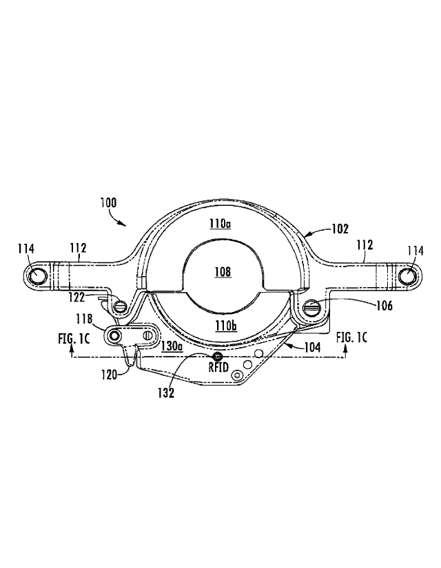
Rom Figure 1A is a schematic perspective view of an elevator, according to
one embodiment of the disclosure.
pm] Figure 18 is a schematic top view of the elevator of Figure 1A,
according to one embodiment of the disclosure.
[0012] Figure 1C is a schematic sectional view along line "Fig. 1C ¨ Fig.
1C"
of the elevator illustrated in Figure 1B.
[0013] Figure 1D is an enlarged partial view of Figure 1C.
[0014] Figure 1E is an enlarged partial view of Figure 1A.
pis] Figure 2A illustrates an enlarged schematic view of a bore prior to
installation of an RFD tag, according to one embodiment of the disclosure.
[0016] Figure 28 illustrates an enlarged view of Figure 2A.
[0017] Figure 2C illustrates an RFD tag prior to installation in a bore,
according to one embodiment of the disclosure.
3
CA 03010316 2018-06-29
WO 2017/127359
PCT/1.152017/013777
[0018] Figure 3A illustrates a partial schematic view of an upper rib
extension
having a bore formed therein, according to another embodiment.
[0019] Figure 38 illustrates an enlarged partial view of Figure 3A.
[0020] Figures 4A and 48 illustrate views of a treated bore and an
untreated
bore, respectively, according to one embodiment of the disclosure.
[0021] Figures 5A-5E illustrate an installation process for an RFID tag,
according to one embodiment of the disclosure.
[0022] Figure 6A is a schematic perspective view of a master bushing,
according to one embodiment of the disclosure.
[0023] Figure 68 is an enlarged partial view of Figure 6A.
[0024] Figure 7A is a schematic perspective view of a spider, according to
one embodiment of the disclosure.
[0025] Figure 78 is an enlarged partial view of Figure 7A.
[0026] Figure 8A is a schematic perspective view of a slip, according to
one
embodiment of the disclosure.
[0027] Figure 88 is an enlarged partial view of Figure 8A.
[0028] Figure 9A is a schematic perspective view of a bowl, according to
one
embodiment of the disclosure.
[0029] Figure 98 is an enlarged partial view of Figure 9A.
[0030] Figure 10A is a schematic perspective view of a lug jaw, according
to
one embodiment of the disclosure.
4
CA 03010316 2018-06-29
WO 2017/127359
PCT/1152017/013777
[0031] Figure 10B is an enlarged partial view of a Figure 10A.
[0032] Figure 11A is a schematic perspective view of tong assembly,
according to one embodiment of the disclosure.
[0033] Figure 11B is an enlarged partial view of a Figure 11A.
[0034] To facilitate understanding, identical reference numerals have been
used, where possible, to designate identical elements that are common to the
figures. It is contemplated that elements and features of one embodiment may
be
beneficially incorporated in other embodiments without further recitation.
DETAILED DESCRIPTION
[0035] The present disclosure generally relates to elevators and other
tools
having radio frequency identification (RFID) tags embedded therein to
facilitate
identification of the elevators. The tools include an RFID tag embedded
therein
to facilitate identification of the tool. The RFID tag may be disposed in a
bore
formed in tool, and then optionally covered with a capping material.
[0036] Figure 1A is a schematic perspective view of an elevator 100,
according to one embodiment of the disclosure. Figure 1B is a schematic top
view of the elevator 100, according to one embodiment of the disclosure.
Figure
1C is a schematic sectional view along line "Fig. 1C ¨ Fig. 1C" of the
elevator
100 illustrated in Figure 1B. Figure 1D is an enlarged partial view of Figure
1C.
Figure 1 E is an enlarged partial view of Figure 1A. To facilitate
explanation,
Figures 1A-1E will be explained in conjunction.
[0037] The elevator 100 includes a body 102 and a door 104 configured in a
circular arrangement and defining a central opening 108. The door 104 is
pivotably coupled to the body 102 via a pin 106 at a hinge 107. The door 104
CA 03010316 2018-06-29
WO 2017/127359
PCT/1JS2017/013777
pivots about an axis of the pin 106 to permit ingress and egress of a tubular
(not
shown), such as drill pipe, into and out of the central opening 108. Each of
the
body 102 and the door 104 include respective shoulders 110a, 110b on upper
surfaces thereof to engage a profile of the tubular when the elevator 100
supports the tubular during a lifting operation.
[0038] The elevator 100 also includes one or more handles 112 (two are
shown) extending radially outward from and integrally formed with the body
102.
A fastener 114, such as a bolt, is disposed through a radially-outward end of
each handle 112 and couples an upper portion 116a of the handle 112 to a lower
portion 116b of the handle 112. The bolt may be selectively removed to secure
or release a linkage to a respective handle 112.
[0039] A locking apparatus 118 is secured to upper and lower rib extensions
130a, 130b of the door 104 opposite the pin 106. The locking apparatus 118
engages a latch 120 coupled to the body 102. The latch 120 pivots about a pin
122 to engage the locking apparatus 118, thereby coupling an outward end of
the
door 104 to the body 102 and maintaining the elevator in a closed orientation,
as
shown. The latch 120 may be biased into engagement with the locking
apparatus 118 via latch spring 128, and secured by a latch lock spring 129.
The
latch lock spring 129 is coupled to a handle 131 positioned between the upper
and lower rib extensions 130a, 130b of the door 104. Manual actuation of the
handle 131 releases the latch lock spring 129, as well as the latch 120 from
the
locking apparatus 118, thereby allowing opening of the door 104.
[0040] The upper and lower rib extensions 130a, 130b extend radially
outward
from the door 104 and are positioned parallel to one another. The upper rib
extension 130a includes an RFID tag 132 embedded in an upper surface thereof
to facilitate identification of the elevator 100. Additionally, the upper rib
extension
130a may also include a nameplate 135a disposed on an upper surface thereof
6
CA 03010316 2018-06-29
WO 2017/127359
PCT/1JS2017/013777
adjacent the RFC tag 132 to facilitate visual identification of the RFID tag
132
location. A second nameplate 135b may be positioned on the door 104 between
the upper and lower rib extensions 130a, 130b. The second nameplate 135b
may include identifying information for the elevator 100. The information of
nameplate 135b may be information also stored on the RFID tag 132. The
information stored on the RFID tag 132 may include one or more of: make, model
number, characteristics of the particular elevator 100, maintenance history,
time
on location, maintenance and/or inspection requirements, and GPS location.
Additionally as discussed above, conventional elevators include only a
nameplate to assist in identification of the elevator. However, the nameplate
is
often unreadable, obscured, or missing, and therefore, identification of
conventional elevators is difficult and time consuming.
100411 For example, if a nameplate is missing from a conventional elevator,
it
may be necessary to determine the proper elevator for a specific tubular size,
load rating, and/or link compatibility through trial and error, which can be
burdensome and introduce human error. In contrast, the elevator 100 of the
present disclosure can easily be identified by an RFID tag reader available to
equipment operators or other personnel tasked with identifying the elevator
100
Using an RFID tag and associated reader for identification purposes eliminates
trial and error identification methods. Example RFID tags include the InfoChip
DuraPlug9.5 UHF. However, it is contemplated that other wireless
identification
tags may be utilized.
100421 As illustrated in Figures 1D and 1E, the RFID tag 132 is positioned
in a
bore 134 formed in the upper surface of the upper rib extension 130a. A
countersink 136 may be formed adjacent to the bore 134. A spot-face 139 may
be positioned adjacent the countersink 136 to facilitate formation of the
countersink 136 and the bore 134. The spot-face 139 and/or the countersink 136
facilitate repeatable accuracy in machining. The countersink 136, and
optionally
7
per415,20.7.10.4777
the soovape.:1.$9, may be :mad vOth :tapping material (not shown ;for clarity)
,to
.secure the. RFIE;). tag 132 NOV:41 the bore. 134, in one example; .the
capping
Material: they be placed i :the pouriteraink. 136 oriti[ :coplanar with the:
lOwer.
:surface Of the spcg000 13 Suitable
capping Melon* Iflude epoxies,
deraMiC, :Other hiateriale Which suitably protect the..,RFip too
oz od..eijoiv treneinieeion identifong itifortotion thetoircoot,:l.
.(0001 to: one
example, the :pore. 134 may be formed 'W a depth A. to seat the
:.if3r.ip tog 112 thereln, The depth 6 may laein.e. range Of .00040
Milliniettera to
:about 9 mdiimeters, such as avoi.4 -3:5 morheters:. such an
example, : the
=OO.Onterair*13.6..roay. be fortieoto.o depth- 8, ON the capping have
:a thickness equal to or less thart.the depth 0õ: In One ekaMple,. the depth
arnIcly
be :aivot 2 5 TO about '3,8 millimeters, such as about 29 Millinietere, The
composition and thickness 0;0e:capping Material Maybe Selettecrlb allow for =
.rernoV:al.Of the capping Material to:allow
replacement Orrefuthishinent of the
:RFID tag 132,. as 'desired In One example, a licorte-cOntaining tapping
material or UrethanarcOntaining tapping. Material is contemplated: In One
example, the dapping material is an epoxy: Examples of capping material
include
butare.n.otlimitedto: RTV.41IGH TEMP: (28B), ELLSWORTH EP1305and LOC,
11TE EA E40CL.
(0001: 'In one:
example., RT1/441-110,1-1 TEMP (28B) includes the following
composition :'48q8 utt4 poly (dieinthlyslloxane), hydroxy terminated; 7-13
w.t.,746
,amorphous. silica; Avt-.QA: petroleum, distallates; 1-5 ,wt-%:: iron
:oxide;. w.WNi
thethyltriaCetoxyailana:;. wt-%.
ethyltriacetcxysilano: anti 176 wt-% titanium
dioxide in One axaMple, -ELLSWORTH Fp.1:$05: la ail epoxy:, A fi:est coMpoon0
of
.thia:epoxy May include 40L50 wtfP4.4-nonylphenol;:3048 wt-
WpOly(a0rylOnititile-
Cobutadierie; 1.0424. wt- 4 1,9,(2-Athiriciethyl)piperazine: and 5-10 Wt%
sitoxenes
anWor silicones=A second compound Of the :epoxy May Include 70-$0 .*4.7%
biaPhenOtMepirObrohydrin) epoxy mein; 710,210..107% 1, 2, 3:7propanetflyV
ester
8
CA 3010316 2019-10-25
CA 03010316 2018-06-29
WO 2017/127359
PCT/1JS2017/013777
of 12-(oxiranylmethoxy-9-octadecanoic add; 2.5-5 wt-% siloxanes and/or
silicones; and 0.1-1 wt-% carbon black.
[0046] While Figures 1A-1E illustrate one embodiment of an elevator 100,
other embodiments are also contemplated. In another embodiment, it is
contemplated that the RFID tag 132 may be embedded in a location other than
the upper rib extension 130a. For example, it is contemplated that the RFID
tag
132 may be embedded in another part of the door 104, or in the body 102. The
location of the RFID tag 132 may be selected to allow for easy scanning of the
RFID tag 132 with an RFID tag reader.
(0046] Figure 2A illustrates an enlarged schematic view of a bore 134 prior
to
installation of an RFID tag 132. Figure 2B illustrates an enlarged view of
Figure
2A. Figure 2C illustrates an RFID tag 132 prior to installation in the bore
134. To
facilitating understanding, Figures 2A-2C will be explained in conjunction.
[0047] As described the above, the bore 134 may extend to a depth A within
the upper rib extension 130a, while the countersink 136 may extend to a depth
B.
The countersink 136 transitions to the bore 134 at an upper shoulder 250. The
upper shoulder 250 may include a horizontal surface 251 extending between a
sidewall of the countersink 136 and a sidewall of the bore 134. The width of
the
countersink 136 at the intersection of the horizontal surface 251 may be about
10
millimeters to about 11 millimeters. The width of the countersink 136 at an
upper
end thereof may be about 12.5 millimeters to about 13.5 millimeters. The
horizontal surface 251 may have a width within a range of about 0.2
millimeters
to about 1 millimeter, such as about 0.5 millimeters. The radius of curvature
of
the upper shoulder 250 may be within a range of about 0.1 millimeters to about
0.5 millimeters, such as about 0.25 millimeters. A spot-face may optionally be
formed adjacent the countersink 136, however, the spot-face is not shown in
Figure 2A for clarity.
9
CA 03010316 2018-06-29
WO 2017/127359
PCT/US2017/013777
[0048] A lower shoulder 252 is positioned radially inward and below the
upper
shoulder 250. The lower shoulder may have a radius of curvature within a range
of about 0.1 millimeters to about 0.5 millimeters, such as about 0.35
millimeters.
The lower shoulder 252 may be spaced about 0.25 millimeters to about 1
millimeter from the upper shoulder 250, such as about 0.65 millimeters. A
vertical sidewall 253 extends between the upper shoulder 250 and the lower
shoulder 252 and defines a counterbore. The walls of the countersink 136 may
be formed at an angle alpha relative to the vertical sidewall 253, such as
about
15 degrees to about 35 degrees_ In one example, the angle alpha is 22 degrees.
The height of the vertical sidewall 253 may be about 0.2 millimeters to about
1
millimeters, such as about 0.6 millimeters. A second vertical sidewall 254 is
positioned below the lower shoulder 252, and extends to a bottom 255 of the
bore 134. Thus, due to the position of shoulders 250, 252, the bore 134 and
the
counter bore 136 define multiple diameters, wherein the lower diameter is less
than the upper diameter. In one example, the lower diameter may within a range
of about 9 millimeters to about 10 millimeters, such as about 9.4 millimeters.
The
upper diameter (e.g., the diameter of the counterbore) may be within a range
of
about 9 millimeters to about 10 millimeters, such as about 9.6 millimeters.
[0049] The multiple diameters of the bore 134 and counter bore 136
facilitate
proper seating of the RFID tag 132 via formation of an interference fit, as
well as
improving axial alignment of the RFID tag. The RFID tag 132 includes a body
256 having a lower shoulder 257, an upper shoulder 258, and a plurality of
ribs
259 (two are labeled) running axially along an outer surface of the body 256.
The ribs 259 may be equally spaced about the circumference of the body 256,
for
example, about every 30 degrees to about every 40 degrees, and may connect
with the upper should 258. The ribs 259 may extend partially along the axial
length of the body 256, such as about 50 percent to about 80 percent along the
length, and include a tapered lower surface 261 to facilitate guidance of the
RFID
CA 03010316 2018-06-29
WO 2017/127359
PCT/1JS2017/013777
tag 132 into the bore 134. In one example, the body 256 has an axial length
about 3 millimeters to about 4 millimeters, such as about 3.5 millimeters.
groscq The diameter of ribs 259 on opposite sides of the body 256 is
greater
than the diameter of the second vertical sidewall 254 of the bore 134.
However,
the diameter of the body 256 is less than the diameter of the vertical
sidewall
254. As the RFID tag 132 is positioned in the bore 134, an interference fit
occurs
between the bore 134 and the ribs 259, thus maintaining the RFID tag 132 in
the
bore 134, even in the absence of an adhesive or cover material. Elimination of
an adhesive improves the transmitting qualities of the RFID tag 132 by
reducing
signal interference. To facilitate insertion and seating of the RFID tag 132
in the
bore 134, the RFID tag 132 may include an axial recess 260 in the body 256 to
allow the escape of gas from beneath the RFID tag 132, thus allowing complete
seating of the RFID tag 132 against the bottom 255 of the bore 134. In the
seated position, a lower surface of the upper shoulder 258 of the RFID tag 132
may engage the upper shoulder 250 of the bore 134. In some examples, a fluid-
tight seal may be formed between the RFID tag 132 and the shoulder 250.
[0051] While the embodiments of Figures 2A-2C describe installation of an
RFID tag without the use of an adhesive, it is contemplated that an adhesive
may
be used in addition to the interference to further secure the RFD tag 132 in
the
bore 134.
10052] Figure 3A illustrates a partial schematic view of an upper rib
extension
330a having a bore 134 formed therein, according to another embodiment.
Figure 3B illustrates an enlarged partial view of Figure 3A. The upper rib
extension 330a is similar to the upper rib extension 130a, and may be used in
place thereof. However, the upper rib extension 330a lacks a countersink.
Thus,
the upper shoulder 250 transitions between a vertical sidewall 253 and a lower
surface of the spot-face 139. Due to exclusion of a countersink, the bottom
11
CA 03010316 2018-06-29
WO 2017/127359
PCT/1JS2017/013777
surface of the bore 134 may be formed about 4 millimeters to about 5
millimeters,
such as about 4.6 millimeters, from an upper surface 361 of the upper rib
extension 330a. In one example, the spot-face 139 may have a depth of about
0.2 millimeters to about 0.6 millimeters, such as about 0.4 millimeters. The
upper
rib extension 330a may accept an RFID tag as similar described above.
[0053] Figures 4A and 4B illustrate views of a treated bore 470 and an
untreated bore 472, respectively, according to one embodiment of the
disclosure.
The treated bore 470 has been tapped to create thread-form features 471 on an
internal surface of the bore 134. For example, the thread-form features 471
may
be formed on the second vertical sidewall 254 illustrated in Figure 3A. The
thread-form features 471 interact with the ribs 259 of an RFID tag 132 (shown
in
Figure 2C) to facilitate retention of the RFID tag 132 in the bore 134 via an
improved interference fit. For example, the thread-form features 471 are
approximately perpendicular to ribs 259 as the RFID tag 132 is inserted into
the
bore 134. During insertion, the ribs 259, which are formed of a softer
material
than the thread-form features 471, elastically deform. Specifically, the ribs
259
compress at the thread-form features 471, and expand between the crests of the
thread-form features 471. In one example, the thread-form feature 471 may
include about 2 to about 4 threads in the bore.
loom In contrast, the untreated bore 472 lacks thread-form features and has
relatively smooth surfaces resulting from a bore formation process, such as
drilling or milling. The relatively smooth surfaces of the untreated bore 472
do
not secure an RFID tag as well as the treated bore 470. In addition, the
treated
bore 470 facilitates removal of an RFID tag in the event the RFID tag requires
replacement. Due to presence of the thread-form features 471, an RFID tag may
be engaged by a tool bit unscrewed, greatly simplifying the removal process.
12
CA 03010316 2018-06-29
WO 2017/127359
PCT/1JS2017/013777
[0055] Figures 5A-5E illustrate an installation process for an RFID tag
132,
according to one embodiment of the disclosure. Figure 5A illustrates an upper
rib extension 330a of an elevator after formation and treating of a bore 134.
As
described above, a spot-face 139 may be formed in the upper rib extension 330a
(partially illustrated) to provide a planar and/or uniform reference surface
for
further machining, such as drilling or milling. Subsequently, the bore 134 may
be
formed, for example via drilling, and then tapped to form thread-form features
471 on the second vertical sidewalls 254 (shown in Figure 3A) of the bore 134
An optional corrosion-inhibitor may then be applied to the exposed surfaces.
An
RFID tag 132 is then be positioned proximate to the bore 134, as shown in
Figure 5A. Once axially aligned, the RFID tag 132 may be lowered into the bore
134, as shown in Figure 58.
[0056] The RFID tag 132 is lowered until the tapered lower surfaces 261
(shown in Figure 2C) of the ribs 259 (two are labeled) engage an upper
shoulder
250 (shown in Figure 3A) of the oounterbore. Contact of all or most of the
ribs
259 with the upper should 250 indicates axially alignment and proper
positioning
of the RFID tag 132 with respect to the bore 134, thereby reducing or
preventing
damage to the RFID tag 132 during installation. Subsequently, the RFID tag 132
is driven into the bore 134 by a driving tool 575. The driving tool 575 may be
a
cylindrical rod having a planar surface on a lower end thereof to engage the
RFID tag 132 and apply even pressure while driving the RFID tag 132 into the
upper rib extension 330a. The RFID tag 132 may be manually or mechanically
driven into the bore 134. As the RFID tag 132 is driven into the bore 134, the
ribs 259 engage the thread-form features 471 to create an interference fit,
thus
maintaining the RFID tag 132 in the bore 134 without the use of an adhesive.
10057] The RFID tag 132 is driven until the RFID tag contacts the bottom
surface 255 (shown in Figure 3A) of the bore 134. Gas escapes from beneath
the RFID tag via an axial recess 260, thus allowing complete seating of the
RFID
13
CA 03010316 2018-06-29
WO 2017/127359
PCT/1JS2017/013777
tag 132 within the bore 134. Additionally, in the seated configuration, an
upper
shoulder 258 of the RFID tag 132 engages the upper shoulder 250 of the bore
134, forming a seal therebetween. The upper shoulder 258 is thus positioned
proximate to the sidewall 253 defining the counterbore. In one example, the
upper surface of the RFID tag 132 is co-planar with or recessed below a lower
surface of the spot-face 139 when fully seated. During installation, the RFID
tag
132 may be oriented to maximize transmission/read range of the RFID tag 132.
Subsequently, as illustrated in Figure 5E, an optional capping layer 576 may
be
applied over the RFID tag 132 to seal, protect, and/or secure the RFID tag in
the
upper rib extension 330a. The capping layer 576 may be substantially coplanar
with the upper surface of the upper rib extension 330a. Although not
illustrated, it
is to be understood that an RFID tag 132 is seated in an upper rib extension
130a in a similar manner.
[0058] While embodiments herein refer to placement of the RFID tags in
elevators, it is contemplated that methods described herein may be applicable
to
other equipment in addition to elevators. Examples of other equipment which
may benefit from embodiments herein include elevator links, bushings, power
slips, drill pipe slips, casing slips, drill collar slips, tubing spiders,
casing spiders
and reducer bushings, flush mounted spiders, slip lifters, safety clamps,
Kelly
spinners, rotating mouse hole tools, pipe spinners, tubing tongs, drill pipe
tongs,
casing tongs, beckets, stabbing guides, casing scrapers, torque tools, power
tongs, master bushings, inserts bowls, bowl adapters, and the like.
Additionally,
while one example of an elevator is illustrated, it is contemplated that other
types
of elevators may benefit from embodiments described herein, including solid
body elevators, multi-pipe elevators, hydraulic-operated elevators, air-
operated
elevators, manual elevators, side door elevators, slip-type elevators,
combination
elevator/spider tools, and single joint elevators.
14
CA 03010316 2018-06-29
WO 2017/127359
PCT/1JS2017/013777
[0059] Figure 6A is
a schematic perspective view of a master bushing 670,
according to one embodiment of the disclosure. Figure 6B is an enlarged
partial
view of Figure 6A. The master bushing 670 is usable with elevators, such as
those described herein. In one example, the master bushing 670 may be utilized
with the XP1000 Extreme Performance Landing String System available from
Forum Energy Technologies of Houston, Texas. The master bushing 670
includes a mounting surface 671 into which an RFID 132 may be embedded, as
described above. In such a manner, the master bushing 670 realizes many of
the benefits described herein. Other mounting locations on the master bushing
670 are contemplated.
Nom Figure 7A is
a schematic perspective view of a spider 778, according
to one embodiment of the disclosure. Figure 7B is an enlarged partial view of
Figure 7A. The spider 778 is a hinged casing spider, and may have an internal
diameter of about 2 3/8 inches to 30 inches, or more. An exemplary spider 778
is available from Forum Energy Technologies of Houston, Texas. The spider 778
includes a mounting surface 779 in which an RFID tag 132 may be embedded,
as described above. In such a manner, the spider 778 realizes many of the
benefits described herein. Other mounting locations on the spider 778 are
contemplated.
[0061] Figure 8A is
a schematic perspective view of a slip 885, according to
one embodiment of the disclosure. Figure 8B is an enlarged partial view of
Figure 8A. An exemplary slip 885 is available from Forum Energy Technologies
of Houston, Texas. The slip 885 includes a mounting surface 886 into which an
RFID tag 132 is embedded. In such a manner, the slip 885 realizes many of the
benefits described herein. Other
mounting locations on the 885 are
contemplated.
CA 03010316 2018-06-29
WO 2017/127359
PCT/1JS2017/013777
[0062] Figure 9A is a schematic perspective view of a bowl 990, according
to
one embodiment of the disclosure. Figure 9B is an enlarged partial view of
Figure 9A. The bowl 990 is usable with master bushings, such as those
described herein. In one example, the bowl 990 may be utilized with the XP1000
Extreme Performance Landing String System available from Forum Energy
Technologies of Houston, Texas. The bowl 990 includes a mounting surface 991
into which an RFID 132 may be embedded, as described above. In such a
manner, the bowl 990 realizes many of the benefits described herein. Other
mounting locations on the bowl 990 are contemplated.
[0063] Figure 10A is a schematic perspective view of a lug jaw 1092.
according to one embodiment of the disclosure. Figure 10B is an enlarged
partial view of a Figure 10A. An exemplary lug jaw 1092 is available from
Forum
Energy Technologies of Houston, Texas. The lug jaw 1092 includes a mounting
surface 1093 into which an RFID tag 132 is embedded. In such a manner, the
lug jaw 1092 realizes many of the benefits described herein. Other mounting
locations on the lug jaw 1092 are contemplated.
pm Figure 11A is a schematic perspective view of tong assembly 1194,
according to one embodiment of the disclosure. Figure 11B is an enlarged
partial view of a Figure 11A. In one example, the lug jaw 1092 may be utilized
with the tong assembly 1194. However, it is contemplated that other lug jaws
may be utilized with the tong assembly 1194 for as well. An exemplary tong
assembly 1194 is available from Forum Energy Technologies of Houston, Texas.
The tong assembly 1194 includes a mounting surface 1195 into which an RFID
tag 132 is embedded. In such a manner, the tong assembly 1194 realizes many
of the benefits described herein. Other mounting locations on the tong
assembly
1194 are contemplated.
16
CA 03010316 2018-06-29
WO 2017/127359
PCT/1.152017/013777
[0065] In some examples, the mounting locations described herein are
selected to be areas of low stress when a particular tool is under full load.
As
such, damage to the RFID tag, or the likelihood of an RFID tag inadvertently
coming loose, is minimized while tool integrity is maintained. However, it is
contemplated that other areas of the tool may be utilized for securing an RFID
tag. For example, it is contemplated that tools may have more than one area of
relatively low stress. In one example, the RFID tag is mounted at the spot of
lowest stress under full load.
[0066] Benefits of the disclosure include expedited and more accurate
identification of elevators. Because the elevators utilize RFID tags rather
than
nameplates to provide a primary method of identification, the disclosed
elevators
can more easily be identified than conventional elevators. Additionally, the
disclosed elevators utilized an embedded RFID tag which is more protected than
externally-secured RFID tags. Therefore, the RFID tags of the disclosed
elevators are less likely to be unintentionally damaged or removed during
operations. In addition, some tools, such as elevators or other equipment, may
bear dual load ratings, dependent upon how the tool is dressed and for what
style of pipe is being handled. Such tools may lack adequate space to properly
identify the dual load ratings. However, the RFID tags of the present
disclosure
obviate the spacing issues, and facilitate identification of this information
by an
operator.
[0067] While the foregoing is directed to embodiments of the present
disclosure, other and further embodiments of the disclosure may be devised
without departing from the basic scope thereof, and the scope thereof is
determined by the claims that follow.
17