Note: Descriptions are shown in the official language in which they were submitted.
CA 03010407 2018-06-29
WO 2017/094012 PCT/1L2016/051288
A DEVICE FOR REMINDING A USER TO DRINK FROM A CONTAINER
BACKGROUND OF THE INVENTION.
1. Field of the Invention
[0001] The
present invention generally relates to a reminder system, and more
specifically relates to a device configured in the container for reminding a
user to drink.
2. Description of Related Art
[0002]
Water is crucial to the human being. Every system in the body depends on
water. The human body made up of between 55 and 75 percent water, is in need
of
timely water replenishment. Lack of water can lead to dehydration, a condition
that
occurs when someone does not have enough water in his/her body to carry on
normal
functions. Even mild dehydration - as little as a 1 percent to 2 percent loss
of the body
weight ¨ can exhaust the energy and make the person tired.
[0003]
Dehydration poses a particular health risk for the very young and
the very old. Signs and symptoms of dehydration includes but not limited to
excessive
thirst, fatigue, headache, dry mouth, little or no urination, muscle weakness,
dizziness
etc. People seem to carry bottled water everywhere they go. Health
practitioners all
over the world suggest drinking of eight glasses water a day.
[0004]
Though people of different ages and weight may require drinking
different amount of water per day, as there are plenty of other reasons to
drink water.
The major reasons for drinking water includes maintaining the balance of body
fluids,
controlling calories, energizing muscles, maintaining skin quality, and
helping kidneys.
[0005] It
is has been widely noted that people forget to drink water on
regular basis. In order to remind people of the need to regularly and
consistently drink
water, health care provider recommends people to use an alarm or watch.
Therefore
there is a need of a device attached with the container to remind about
drinking water at
regular interval of times.
1
CA 03010407 2018-06-29
WO 2017/094012 PCT/1L2016/051288
SUMMARY OF THE INVENTION
[0006] In accordance with the teachings of the present invention, a
clip-on
device attached to a cap of a container for reminding a user is provided.
[0007] In some embodiments the clip-on device may include a cover
attachable to a container, at least one signal producing unit located in the
cover, a tap
button located on the exterior of the cover and a controller. In some
embodiments the
controller may be configured to: initiate a timeout period when the tap button
is tapped
and activate the at least one signal producing unit if the tap button is not
tapped before
the lapse of the timeout period.
[0008] In some embodiments, the controller is further configured to
restart
the timeout period when the tap button is tapped. In some embodiments, the
signal
producing unit comprises at least one of: an audio unit; one or more light
emitting
sources; and a vibration unit. In some embodiments, the controller is further
configured
to increase the intensity of the signals produced by the signal producing unit
after the
lapse of the timeout period until the tap button is tapped. In some
embodiments, the
controller is further configured to change the frequency of the signals
produced by the
signal producing unit after the lapse of the timeout period until the tap
button is tapped.
[0009] In some embodiments, the cover is fittable over a cap of the
container. In some embodiments, the cover comprises an exterior indented
portion, and
the tap button is located inside the exterior indented portion.
[0010] In some embodiments, the controller and the at least one
signal
producing unit are located on a printed circuit board placed in the cover.
[0011] In some embodiments, the clip-on device further includes one
or
more sensors in the cover for sensing an environmental condition and wherein
the
controller is further configured to adjust the timeout period based on the
sensed
environmental condition. In some embodiments, when the sensor is light sensor
and the
controller is further configured to pause or extend the timeout period when
the light
sensor senses a reduction in light. In some embodiments, when the sensor is a
2
CA 03010407 2018-06-29
WO 2017/094012 PCT/1L2016/051288
thermometer and the controller is further configured to shorten the timeout
period based
on an increase in sensed temperature.
[0012] Some embodiments of the invention are directed to an in-cap
device for attaching to a container having a spout. The in-cap device may
include, a
cover to cover the spout of the container, a hollow lock located in the cover,
for
receiving the spout when the cover is in a closed position over the container,
at least
one signal producing unit, a button located between the cover and the hollow
lock such
that when the cover is in a closed position over the container, the button is
pressed
against the spout and a controller. The controller may be configured to:
initiate a timeout
period when the button is pressed and activate the at least one signal
producing unit if
the button is not detached from the spout before the lapse of the timeout
period.
[0013] In some embodiments, the controller is further configured to
restart
the timeout period when the button is pressed against the spout. In some
embodiments,
the controller is further configured to increase the intensity of the signals
produced by
the signal producing unit after the lapse of the timeout period until the
button is pressed
against the spout. In some embodiments, the controller is further configured
to change
the frequency of the signals produced by the signal producing unit after the
lapse of the
timeout period until the button is pressed against the spout.
[0014] In some embodiments, the controller is located between the
hollow
lock and the cover. In some embodiments, the controller and the at least one
signal
producing unit are located on a printed circuit board placed between the
hollow lock and
the cover.
[0015] In some embodiments, the cover is openable or closable in a
single
act. In some embodiments, the signal producing unit is located between the
hollow lock
and the cover.
[0016] In some embodiments, the in-cap device may further include
one
or more sensors in the cover for sensing an environmental condition and
wherein the
controller is further configured to adjust the timeout period based on the
sensed
environmental condition. In some embodiments, when the sensor is light sensor
and the
3
CA 03010407 2018-06-29
WO 2017/094012 PCT/1L2016/051288
controller is further configured to pause or extend the timeout period when
the light
sensor senses a reduction in light. In some embodiments, when the sensor is a
thermometer and the controller is further configured to shorten the timeout
period based
on an increase in sensed temperature.
[0017] In
some embodiments, the signal producing unit comprises at least
one of: an audio unit; one or more light emitting sources; and a vibration
unit.
[0018]
These and other features and advantages will become apparent
from the following detailed description of illustrative embodiments thereof,
which is to be
read in connection with the accompanying drawings.
BRIEF DESCRIPTION OF DRAWINGS
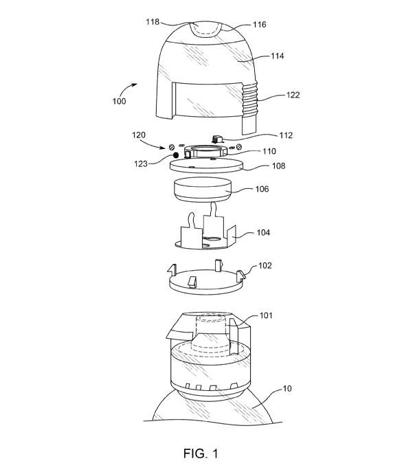
[0019]
FIG. 1 illustrates an exploded view of a clip-on device attached to a
cap of a container for reminding a user in accordance with some embodiments of
the
present invention;
[0020]
FIG. 2 illustrates a perspective view of the clip-on device in
accordance with some embodiments of the present invention;
[0021]
FIG. 3 illustrates a perspective view of the clip-on device attached
to the cap of the container in accordance with some embodiments of the present
invention;
[0022]
FIG. 4 illustrates another exploded view of an in-clip device
detachably attached to the container in accordance with some embodiments of
the
present invention;
[0023]
FIG. 5 illustrates another perspective view of the in-clip device in
accordance with some embodiments of the present invention; and
[0024]
FIG. 6 illustrates a perspective view of the in-cap device attached to
the container in accordance with some embodiments of the present invention.
4
CA 03010407 2018-06-29
WO 2017/094012 PCT/1L2016/051288
[0025] The foregoing summary, as well as the following detailed
description of certain embodiments of the present invention, will be better
understood
when read in conjunction with the appended drawings. For the purpose of
illustrating the
invention, certain embodiments are shown in the drawings. It should be
understood,
however, that the present invention is not limited to the arrangements and
instrumentality shown in the attached drawings.
DETAILED DESCRIPTION OF DRAWINGS
[0026] While this technology is illustrated and described in an
embodiment
of the invention, a reminder system attached with a container, may be produced
in
different sizes, shapes and colors. This is depicted in the drawings, and will
herein be
described in detail, as one embodiment of the invention, with the
understanding that the
present disclosure is to be considered as an exemplification of the principles
of the
invention and the associated functional specifications for its construction
and is not
intended to limit the invention to the embodiment illustrated. Those skilled
in the art will
envision many other possible variations within the scope of the technology
described
herein.
[0027] FIG. 1 illustrates an exploded view of a clip-on device 100
attached
to a cap 101 of a container 10 for reminding a user in accordance with some
embodiments of the present invention. In some embodiments, clip-on device 100
includes a cover 114 attachable to container 10, at least one signal producing
unit 120
located in cover 114, a tap button 110 located at the exterior of cover 114
and a
controller 112 located in cover 114. Clip-on device 100 may further include, a
bottom
cover 102 located inside cover 114 to be placed on the top of the cap 101 of
the
container 10, a battery holder 104 placed on top of the bottom cover 102. In
some
embodiments, cover 114 is fittable over cap 101 of container 10.
[0028] The clip-on device 100 may further include a battery 106
placed
inside the battery holder 104, a printed circuit board 108 attached to the
battery holder
104 placed inside in cover 114 such that button 110 and controller 112 are
placed on
printed circuit board 108 . In some embodiments, controller 112 may be
configured to
CA 03010407 2018-06-29
WO 2017/094012 PCT/1L2016/051288
initiate a timeout period when button 110 is tapped and activate signal
producing unit
120 if tap button 110 is not tapped before the laps of the timeout period. In
some
embodiments, controller 112 may further be configured to store a reference
time at
which the button was tapped and the timeout period . In some embodiments,
controller
112 is further configured to restart the timeout period when tap button 110 is
tapped.
[0029] In some embodiments, cover 114 may be attached to the bottom
cover 102 for housing the battery holder 104, the battery 106, the printed
circuit board
108, the button 110, the controller 112. Further, the cover 114 includes an
indent 116.
[0030] In some embodiments, cover 114 includes an exterior indented
portion 116 and tap button 118 is located inside exterior indented portion
116. In some
embodiments, when button 118 meets the button 110 on receiving a tap from the
user,
at least one signal producing unit 120 connected to the printed circuit board
108 to
produce signals wh receiving instructions from the controller 112. Further the
controller
112 may store the reference time on receiving the tap from the user.
[0031] The controller 112 may generate the signals (e.g., reminding
signals) for the user to drink from the container, when the user fails to tap
the tap button
118 again in duration of the stored timeout period from the reference time. In
some
embodiments, the user partially removes the upper cover 114 to access the
spout of the
container.
[0032] In some embodiments of the present invention, the tap button
118
facilitates the user to push the upper cover 114 to close the cap 101 of the
container 10.
Further, the clip-on device 100 includes one or more grooves 122 on the lower
circumference to detachably attach the upper cover 114 to the container 10.
[0033] In some embodiments of the present invention, the clip-on
device
100 includes one or more sensors 123 located in cover 114, for example,
connected to
the printed circuit board 108, for sensing environmental conditions of the
upper cover
114. Examples of the sensors 123 include but not limited to ultraviolet
sensor, humidity
sensor, touch sensor, temperature sensor and the light sensor.
6
CA 03010407 2018-06-29
WO 2017/094012 PCT/1L2016/051288
[0034] In some embodiments, controller 112 may further be configured
to
adjust the timeout period based on the sensed environmental conditions. For
example,
the stored reference timeout period may vary according to the environmental
conditions
at the upper cover 114 as sensed by the one or more sensors 123. In some
embodiments, controller 112 may be configured to shorten the timeout period
based on
an increase in sensed temperature. For example, when the temperature is more
than
350 C, the stored timeout period to send reminder signals may be shorter than
when the
temperature is less than 350 C. In some embodiments, the controller may
calculate a
timeout period based on a formula using the temperature as an input variable.
[0035] In some embodiments, when sensor 123 is light sensor,
controller
112 may further be configured to pause or extend the timeout period when the
light
sensor senses a reduction in light. For example, in night, when the user is
sleeping and
there is no light, there would not be any reminder signal. However, as soon as
the light
sensor detects the light, controller 112 may start the process of sending
signals.
Further, when the user has not touched the upper cover 114 since long, then
the
controller 112 may not send the signals. However, on receiving a touch signal
from the
touch sensor, the controller 112 starts the process of sending reminding
signals again.
[0036] FIG. 2 illustrates a perspective view of the clip-on device
100 in
accordance with some embodiments of the present invention. The tap button 118
is a
touch sensitive sensor placed in the indent. Examples of the output unit 120
includes
but not limited to an audio unit 124, one or more light emitting sources 125a
and 125b,
and a vibration unit 126. The audio unit 124 is connected to the printed
circuit board (not
shown in FIG. 2) to generate audio signals on receiving reminder signals from
the
controller 112.
[0037] The one or more light emitting sources 125a and 125b may be
connected to the printed circuit board (not shown in FIG. 2) to illuminate on
receiving
instructions from the controller 112. The vibration unit 126 may be connected
to the
printed circuit board (not shown in FIG. 2) to produce vibration signals on
receiving
reminder signals from the controller 112.
7
CA 03010407 2018-06-29
WO 2017/094012 PCT/1L2016/051288
[0038] In some embodiments of the present invention, the electrical
circuit
of the clip-on device 100 is printed on the upper housing 114 or the bottom
cover 102.
The upper housing 114 may be made of plastic, however it would be readily
apparent to
those skilled in the art that various types of material may be envisioned
without
deviating from the scope of the present invention.
[0039] In some embodiments, controller 112 is configured to increase
the
intensity of the signals produced by the signal producing unit (e.g., brighter
light, louder
noise, stronger or more prolonged vibrations, etc.) after the lapse of the
timeout period
until the tap button is tapped. In some embodiments, controller 122 may be
configured
to change the frequency of the signals produced by the signal producing unit
after the
lapse of the timeout period until the tap button is tapped. In some
embodiments, the
controller may change both intensity and frequency of the signals. For
example, the
intensity of the output signals may increase and the frequency may increase or
decrease (e.g., to conserve power).
[0040] FIG. 3 illustrates a perspective view of the clip-on device
100
attached to the cap 302 of the container 304 in accordance with some
embodiments of
the present invention. In order to drink from the container 304, the user may
open the
cap 302, resulting in opening of the attached clip-on device 100. The cap 302
and the
clip-on device 100 may be partially pivotally removed to allow the user to
access spout
306 of the container 304.
[0041] FIG. 4 illustrates exploded view of an in-cap device 400
detachably
attached to a container 402 having a spout 404 for reminding a user in
accordance with
some embodiments of the present invention. The in-cap device 400 may include a
cover
418 to cover the spout 404 of the container 402, a hollow lock 406 located in
the cover,
for receiving the spout 404 when the cover 418 is in a closed position over
the container
402, at least one signal producing unit 420, a button 408 located between the
cover 418
and the hollow lock 406 such that when the cover 418 is in a closed position
over the
container 402, the button 408 is pressed against the spout 404 and a
controller 416. In
some embodiments, controller 416 and signal producing unit 420 may be located
on a
8
CA 03010407 2018-06-29
WO 2017/094012 PCT/1L2016/051288
printed circuit board 410 placed on the button 408. The printed circuit board
410 may be
located between the hollow lock 406 and cover 418. Controller 416 may be
configured
to initiate a timeout period when the button 408 is pressed and activate the
at least one
signal producing unit 420 if the button 408 is not detached from the spout 404
before
the lapse of the timeout period.
[0042] Further, the in-cap device 400 may include a battery 412
connected
to the printed circuit board 410, a battery holder 414 for holding the battery
412 In some
embodiments, controller 416 may further be configured to store a reference
time when
the user closes the hollow sealing lock 406 to allow the button 408 to meet
the spout
404. Further, the controller 416 may be configured to store a reference
timeout value
and generating reminding signals.
[0043] The cover 418 may be attached to the container 402 for
housing
the spout 404, the hollow lock 406, the battery holder 414, the battery 412,
the printed
circuit board 410 and the button 408. In some embodiments, the cover 418 may
be
openable or closable in a single act. The signal producing unit 420 may be
connected to
the printed circuit board 410 for producing output signals on receiving
instructions from
the controller 416. The signal producing unit 420 is explained in detailed in
conjunction
with FIG. 5 of the present invention.
[0044] The controller 416 may activate the at least one signal
producing
unit when the user fails to remove the hollow lock 406 along with the button
408 from
the spout 404 again in duration of the stored timeout duration from the
reference time.
In some embodiments, the controller 416 is further configured to restart the
timeout
period when the button 408 is pressed against the spout 404. In some
embodiments,
the user removes the cover 418 along with the hollow sealing lock 406 to
access the
spout 404 for drinking from the container 402.
[0045] In some embodiments of the present invention, the controller
416
may be configured to increase the intensity of the signals produced by the
signal
producing unit 420 after the lapse of the timeout period until the button 408
is pressed
against the spout 404. In some embodiments, the controller 416 may further be
configured to change the frequency of the signals produced by the signal
producing unit
9
CA 03010407 2018-06-29
WO 2017/094012 PCT/1L2016/051288
420 after the lapse of the timeout period until the button 408 is pressed
against the
spout 404. For example, the intensity of the output signals may result in
increase or
decrease in the frequency of the signals released from the output unit. In yet
another
exampleõ the intensity may relates to high intense notifications such as
higher volume
of the sound, increase in length of vibrations, and high light brightness.
[0046] FIG. 5 illustrates another perspective view of the in-clip
device 400
in accordance with some embodiments of the present invention. Examples of the
signal
producing unit 420 include but not limited to an audio unit 502, one or more
light
emitting sources 504 and 125b, and a vibration unit 506. The audio unit 502
may be
connected to the printed circuit board (not shown in FIG. 5) to generate audio
signals on
receiving reminder signals from the controller (not shown in FIG. 5).
[0047] The one or more light emitting sources 504 may be connected
to
the printed circuit board (not shown in FIG. 5) to illuminate on receiving
reminder signals
from the controller (not shown in FIG. 5). The vibration unit 506 may be
connected to
the printed circuit board (not shown in FIG. 5) to produce vibration signals
on receiving
reminder signals from the controller (not shown in FIG. 5).
[0048] In some embodiments, in-cap device 400 further includes one
or
more sensors 508, for example, connected to the printed circuit board 108, for
sensing
environmental conditions reflecting on the upper cover 418. In some
embodiments, the
controller 416 may be further configured to: change the timeout period based
on the
sensed environmental condition. Examples of the sensors 508 include but not
limited to
ultraviolet sensor, humidity sensor, touch sensor, temperature sensor and the
light
sensor.
[0049] Further, in the in-cap device 400 wherein the stored timeout
period
may vary according to the environmental conditions of the upper cover 418 as
sensed
by the one or more sensors 508. In some embodiments, when the sensor 508 is a
thermometer, the controller 416 is further configured to shorten the timeout
period
based on an increase in sensed temperature. For example, when the temperature
is
CA 03010407 2018-06-29
WO 2017/094012 PCT/1L2016/051288
more than 350 C, the stored reference timeout value to send reminder signals
is less
than when the temperature is less than 3500.
[0051] In some embodiments, when the sensor 508 is a light sensor,
the
controller 416 is further configured to pause or extend the timeout period
when the light
sensor senses a reduction in light. For exampleõ in night, when the user is
sleeping and
there is no light, there would not be any reminder signal. However, as soon as
the light
sensor detects the light, the controller (not shown in FIG. 5) starts the
process of
sending reminding signals.
[0052] Further, in some embodiments of the present invention, the in-
cap
400 includes a touch sensitive sensor 510 placed on the battery holder 414 for
receiving
a tap from the user for closing the upper cover 418 against the container (not
shown in
FIG. 5).
[0053] FIG. 6 illustrates a perspective view of the in-cap device
400
attached to the container 402 in accordance with some embodiments of the
present
invention. In order to drink from the spout 404, the user may open the in-cap
device 400
which is pivotally attached to the container 402.
[0054] The present invention may offer various advantages such as to
remind people of the need to regularly and consistently drink water which is
important
for the people's health. The present invention focus on monitoring the
behavior of the
user and reminding to drink is purely on the behavior of the user. The user
needs not to
perform any extra activities to have a balance liquid intake for the body.
[0055] There has thus been shown and described a reminder system
configured with a container. Many changes, modifications, variations and other
uses
and applications of the subject invention will, however, become apparent to
those skilled
in the art after considering this specification and the accompanying drawings
which
disclose the embodiments thereof. All such changes, modifications, variations
and other
uses and applications which do not depart from the spirit and scope of the
invention are
11
CA 03010407 2018-06-29
WO 2017/094012 PCT/1L2016/051288
deemed to be covered by the invention, which is to be limited only by the
claims which
follow.
12