Language selection

Search

Patent 3010503 Summary

Third-party information liability

Some of the information on this Web page has been provided by external sources. The Government of Canada is not responsible for the accuracy, reliability or currency of the information supplied by external sources. Users wishing to rely upon this information should consult directly with the source of the information. Content provided by external sources is not subject to official languages, privacy and accessibility requirements.

Claims and Abstract availability

Any discrepancies in the text and image of the Claims and Abstract are due to differing posting times. Text of the Claims and Abstract are posted:

  • At the time the application is open to public inspection;
  • At the time of issue of the patent (grant).
(12) Patent: (11) CA 3010503
(54) English Title: CONSTRUCTION ELEMENT FOR CONNECTING THERMALLY INSULATED PARTS OF A BUILDING
(54) French Title: ELEMENT DE CONSTRUCTION DESTINE A RELIER DES PARTIES THERMIQUEMENT ISOLEES D'UN BATIMENT
Status: Granted
Bibliographic Data
(51) International Patent Classification (IPC):
  • E04B 1/00 (2006.01)
  • E04C 5/07 (2006.01)
(72) Inventors :
  • MICHIELS, PIERRE (Belgium)
  • REMY, OLIVIER (Belgium)
(73) Owners :
  • PLAKABETON S.A. (Belgium)
(71) Applicants :
  • PLAKABETON S.A. (Belgium)
(74) Agent: LAVERY, DE BILLY, LLP
(74) Associate agent:
(45) Issued: 2024-01-02
(86) PCT Filing Date: 2017-01-03
(87) Open to Public Inspection: 2017-07-20
Examination requested: 2021-12-01
Availability of licence: N/A
(25) Language of filing: English

Patent Cooperation Treaty (PCT): Yes
(86) PCT Filing Number: PCT/EP2017/050076
(87) International Publication Number: WO2017/121658
(85) National Entry: 2018-07-03

(30) Application Priority Data:
Application No. Country/Territory Date
2016/5019 Belgium 2016-01-12

Abstracts

English Abstract

The invention relates to a construction element for forming a connection between two parts of a building that are thermally insulated from one another, comprising an elongate portion comprising a thermally insulating material, and configured to be placed between the parts of the building, bars which run through the thermally insulating portion and which are configured to be anchored in the building parts that are to be connected and thus to absorb the tensile forces between these building parts, and means for absorbing compression and shear forces between the building parts,characterised in that the bars comprise metal bars, as well as non-metallic bars formed of a thermally insulating material, and wherein the metal bars are configured to maintain the connection when the tensile force absorbed by the non-metallic bars is lost.


French Abstract

L'invention concerne un élément de construction destiné à former une liaison entre deux parties d'un bâtiment qui sont thermiquement isolées l'une de l'autre, comprenant une partie allongée comprenant un matériau thermiquement isolant, et conçue pour être placée entre les parties du bâtiment, des barres qui traversent la partie thermiquement isolante et qui sont conçues pour être ancrées dans les parties de bâtiment qui doivent être reliées et pour absorber ainsi les forces de traction entre ces parties de bâtiment, et un moyen permettant d'absorber les forces de compression et de cisaillement entre les parties de bâtiment, caractérisé en ce que les barres comportent des barres métalliques, ainsi que des barres non métalliques constituées d'un matériau thermiquement isolant, les barres métalliques étant conçues pour maintenir la liaison lorsque la force de traction absorbée par les barres non métalliques est perdue.

Claims

Note: Claims are shown in the official language in which they were submitted.

7
CLAIMS
1.Construction element (10) for forming a
connection between two parts of a building that are
thermally insulated from one another, comprising:
= an elongate thermally insulating portion
(11) comprising a thermally insulating material (2),
and configured to be placed between the parts of the
building,
= bars (5, 6) which run through the
elongate thermally insulating portion (11) and which
are configured to be anchored in the building parts
that are to be connected, and thus to absorb the
tensile forces between these building parts,
= means (7) for absorbing compression and
shear forces between the building parts,
characterised in that the bars (5) comprise metal bars, as
well as non-metallic bars (6) formed of a thermally
insulating material, and wherein the metal bars (5) are
configured to maintain the connection when the tensile
force absorbed by the non-metallic bars (6) is lost.
2.Construction element according to claim 1,
wherein the metal bars (5) are placed above the means (7)
for absorbing compression and shearing forces.
3.Construction element according to claim 1
or 2, wherein, on both sides of each metal bar (5), a non-
metallic bar (6) is placed at a short distance from the
metal bar.

8
4.Construction element according to any one
of claims 1 to 3, comprising groups of 3 bars, one central
metal bar (5) and two non-metallic bars (6), symmetrically
placed with respect to the means (7) for absorbing
compression and shearing forces.
5.Construction element according to any one
of claims 1 to 4, wherein the means for absorbing
compression and shearing forces consist of support blocks
(7) that are arranged below in the elongate thermally
insulating portion (11).
6.Construction element according to any one
of claims 1 to 5, wherein the metal bars (5) are made of
steel.
7.Construction element according to any one
of claims 1 to 6, wherein the non-metallic bars (6) are
basalt-based.

Description

Note: Descriptions are shown in the official language in which they were submitted.


1
CONSTRUCTION ELEMENT FOR CONNECTING THERMALLY INSULATED
PARTS OF A BUILDING
Field of the Invention
[0001] The
invention is related to a construction
element applicable to the construction of buildings, in
particular an element for connecting components of a
building that are thermally insulated from one another, e.g.
between a concrete floor and an overhanging floor of a
balcony. These elements are also known as 'thermal breaks'.
Prior Art
[0002]
Connections between internal parts of a
building and overhanging external parts, e.g. a concrete
balcony floor, need to be realized with a minimal impact on
the insulation of the building. For
creating this
connection, elements are known that consist of an elongate
insulating portion provided with reinforcement bars that
run through the insulated portion and absorb the tensile
forces between the parts of the building that are to be
connected. Means are also provided to absorb compression
and shear forces. The latter take the form, e.g. of
pressure bars and bars running diagonally through the
insulating portion, or of specially formed blocks that are
incorporated into the insulating portion. The insulating
portion is placed between the parts of the building which
are to be connected, whilst the various force-absorbing
elements are anchored in said building parts in order to
form the connection.
[0003] Despite
the presence of the insulating
material, the force-absorbing elements are a major source
of heat loss. The steel bars have high heat conductivity
Date Recue/Date Received 2023-06-06

2
and thus form an important thermal bridge. The use of non-
metallic tension bars has not yet been implemented. The
strength of plastic tension bars or other alternatives may
be high enough, but the heat resistance of these bars in
the event of fire is inadequate. For
thermal reasons,
organic insulation materials such as PIR, PUR, EPS, XPS,
etc. which are characterised by low fire resistance, are
frequently used for the insulating portion. However, when
these materials are used in combination with non-metallic
tension members, the load-bearing capacity of the
construction element is reduced or completely eliminated in
the event of fire.
Furthermore, the use of very thick
layers of fire-resistant insulation material is impractical
and expensive.
Summary of Features of the Invention
[0004] The
invention is related to a construction
element. The
construction element serves to form a
connection between two parts of a building that are
thermally insulated from one another, and comprises:
= an elongate portion comprising a thermally insulating
material, and configured to be placed between the
parts of the building,
= bars which run through the thermally insulating
portion and which are configured to be anchored in
the building parts that are to be connected, and thus
to absorb the tensile forces between these building
parts,
= means for absorbing compression and shear forces
between the building parts,
characterised in that the bars comprise metal bars, as well
as non-metallic bars formed of a thermally insulating
material, and wherein the metal bars are configured to
Date Recue/Date Received 2023-06-06

3
maintain the connection when the tensile force absorbed by
the non-metallic bars is lost, i.e. when the non-metallic
bars are damaged or destroyed to the extent that they are
no longer able to absorb any tensile force.
[0005] According to the
preferred embodiment,
'maintain' refers to the preservation of the connection to
a minimal extent in order to prevent collapse.
[0006] According to an
embodiment, the metal bars
are placed above the means for absorbing compression and
shearing forces. A non-
metallic bar may be placed on
either side of each metal bar, at a short distance from the
metal bar.
[0007] According to an
embodiment, the construction
element comprises groups of 3 bars, one central metal bar
and two non-metallic bars, symmetrically placed with
respect to the means for absorbing compression and shearing
forces.
[0008] The means for
absorbing compression and
shearing forces may consist of support blocks that are
arranged below in the elongate portion. The metal bars may
be made of steel. The non-
metallic bars may be basalt-
based.
Brief Description of the Figures
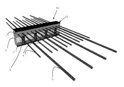
[0009] Fig. 1 shows a
three¨dimensional image of a
construction element according to one embodiment of the
invention.
Detailed Description of Preferred Embodiments of the
Invention
[0010] As shown in fig. 1,
the construction element
10 according to the invention comprises the following
elements: an elongate beam-shaped portion 11 comprising a
Date Recue/Date Received 2023-06-06

4
shell that encloses a thermally insulating material 2, such
as mineral wool or PIR (polyisocyanurate), PUR
(polyurethane), EPS (expanded polystyrene), XPS (extruded
polystyrene). In the embodiment shown, the shell comprises
an upper part l' and a lower part 1". Both
parts are
formed of metallic side walls 3 and a closing cap 4 made of
plastic, e.g. PVC. The
shell may also form a contiguous
whole that completely surrounds the insulating material.
In an upper portion of the shell, a number of bars 5/6 run
through the beam-shamed portion 11 is. The bars 5/6 are
configured to absorb the tensile force between the
connected building parts. In a lower portion of the shell,
support elements 7 are provided to absorb compression and
shearing forces. These are support blocks made of a solid
material, e.g. concrete, with the shape of the block and
the composition of the material configured to absorb both
compression and shearing forces. In and
of itself, this
type of block is known, and is described for example in
document US 2013/0276393. Instead
of these blocks, the
more classic compression bars and bars running diagonally
through the insulation may be provided. The construction
element is placed in a building in the known manner by
placing the insulating beam-shaped portion 11 between two
parts of a building, e.g. between a first concrete floor
inside the building and a second concrete floor that is
connected to the building in an overhanging manner, with
the bars and other force-absorbing elements anchored in the
concrete floors.
[0011] It is
characteristic of the invention that
the construction element comprises both metal tension bars
5 and non-metallic tension bars 6. The non-
metallic
tension bars 6 are thermally insulating. In other words,
they are formed of a thermally insulating material, i.e. a
Date Recue/Date Received 2023-06-06

5
material with negligible or very low heat conductivity.
According to a preferred embodiment, these beams are
basalt-based. For
example, the beams may be made of a
known material formed of a resin into which basalt fibres
are incorporated. Other possible materials include
materials based on glass fibres or Aramid polymers. The
metal bars 5 are preferably made of stainless steel. In the
embodiment shown, steel bars 5 are placed at regular
intervals above the support elements 7 that absorb the
compression and shearing forces. The metal
bars 5 are
preferably welded on the metal side walls 3 of the shell.
On both sides of each metal bar 5, a non-metallic bar 6 is
provided. In the embodiment shown, all bars are arranged
at fixed distances from one another.
[0012] The number
and placement of the metal and
non-metallic bars is not limited however within the context
of the invention. According to one preferred embodiment, 2
non-metallic bars 6 are placed at short distances on either
side of one metal bar 5, so that the construction element
comprises groups of three bars, with each group consisting
of a metal bar 5 and two non-metallic bars 6. The central
metal bars 5 are placed above the support blocks 7 or
equivalent elements. The distances between the groups is
determined by the distances between the supporting blocks 7.
The 'short' distance between the metal bars 5 and the non-
metallic bars 6 arranged on either side is short in
relation to the fixed or average distance between the metal
bars 5. The groups are preferably symmetric with regard to
the support element 7, by the placement of the non-metallic
bars 6 at an equal distance from the central metal bar 5.
[0013] The
length and diameter of the metal bars (in
other words the volume of metal used to produce these bars)
is such that these metal bars by themselves are able to
Date Recue/Date Received 2023-06-06

6
maintain the connection between the building parts to a
minimal extent when the tensile force absorbed by the non-
metal bars is eliminated, for example in the event of a
fire.
[0014] The
length and diameter of the non-metallic
bars is such that the combined tensile force that can be
absorbed by the metal and non-metallic bars is sufficient
to meet the applicable strength standards under normal
circumstances, i.e., when the metal and non-metallic bars
are performing their normal function and neither of them is
compromised or weakened (for example in the event of a
fire).
[0015] Due to
the contribution made by the non-
metallic bars under normal circumstances, the amount of
metal used for the metal bars may be less than in the case
of a connection in which only metal bars are used. This
means that the number of metal bars may be reduced. This
reduces the heat loss caused by these bars, given that the
non-metallic bars have little or no heat conductivity. An
improvement in heat loss of 30 % is possible.
Additionally, the strength is guaranteed under normal
circumstances by the presence of the non-metallic bars. In
the event of fire, and in the worst-case scenario, the
disappearance of the non-metallic bars, a minimum strength
of the connection, sufficient to prevent collapse and allow
for safe evacuation of the building, is guaranteed. The
solution provided by the invention also makes it possible
to produce the construction element without applying very
thick layers of fire-resistant material.
Date Recue/Date Received 2023-06-06

Representative Drawing
A single figure which represents the drawing illustrating the invention.
Administrative Status

For a clearer understanding of the status of the application/patent presented on this page, the site Disclaimer , as well as the definitions for Patent , Administrative Status , Maintenance Fee  and Payment History  should be consulted.

Administrative Status

Title Date
Forecasted Issue Date 2024-01-02
(86) PCT Filing Date 2017-01-03
(87) PCT Publication Date 2017-07-20
(85) National Entry 2018-07-03
Examination Requested 2021-12-01
(45) Issued 2024-01-02

Abandonment History

There is no abandonment history.

Maintenance Fee

Last Payment of $210.51 was received on 2023-12-20


 Upcoming maintenance fee amounts

Description Date Amount
Next Payment if small entity fee 2025-01-03 $100.00
Next Payment if standard fee 2025-01-03 $277.00

Note : If the full payment has not been received on or before the date indicated, a further fee may be required which may be one of the following

  • the reinstatement fee;
  • the late payment fee; or
  • additional fee to reverse deemed expiry.

Patent fees are adjusted on the 1st of January every year. The amounts above are the current amounts if received by December 31 of the current year.
Please refer to the CIPO Patent Fees web page to see all current fee amounts.

Payment History

Fee Type Anniversary Year Due Date Amount Paid Paid Date
Application Fee $400.00 2018-07-03
Maintenance Fee - Application - New Act 2 2019-01-03 $100.00 2018-12-19
Maintenance Fee - Application - New Act 3 2020-01-03 $100.00 2019-12-24
Maintenance Fee - Application - New Act 4 2021-01-04 $100.00 2020-12-18
Request for Examination 2022-01-04 $816.00 2021-12-01
Maintenance Fee - Application - New Act 5 2022-01-04 $204.00 2021-12-15
Maintenance Fee - Application - New Act 6 2023-01-03 $203.59 2022-12-20
Final Fee $306.00 2023-11-07
Maintenance Fee - Application - New Act 7 2024-01-03 $210.51 2023-12-20
Owners on Record

Note: Records showing the ownership history in alphabetical order.

Current Owners on Record
PLAKABETON S.A.
Past Owners on Record
None
Past Owners that do not appear in the "Owners on Record" listing will appear in other documentation within the application.
Documents

To view selected files, please enter reCAPTCHA code :


To view images, click a link in the Document Description column. To download the documents, select one or more checkboxes in the first column and then click the "Download Selected in PDF format (Zip Archive)" or the "Download Selected as Single PDF" button.

List of published and non-published patent-specific documents on the CPD .

If you have any difficulty accessing content, you can call the Client Service Centre at 1-866-997-1936 or send them an e-mail at CIPO Client Service Centre.


Document
Description 
Date
(yyyy-mm-dd) 
Number of pages   Size of Image (KB) 
Request for Examination 2021-12-01 4 89
Examiner Requisition 2023-02-07 4 190
Abstract 2018-07-03 1 85
Claims 2018-07-03 2 46
Drawings 2018-07-03 1 180
Description 2018-07-03 6 232
Representative Drawing 2018-07-03 1 169
International Search Report 2018-07-03 2 46
National Entry Request 2018-07-03 4 108
Request under Section 37 2018-07-09 1 55
Cover Page 2018-07-17 1 100
Response to section 37 2018-07-27 2 88
Electronic Grant Certificate 2024-01-02 1 2,527
Amendment 2023-06-06 18 2,252
Claims 2023-06-06 2 71
Description 2023-06-06 6 368
Final Fee 2023-11-07 4 89
Representative Drawing 2023-12-06 1 70
Cover Page 2023-12-06 1 105