Note: Descriptions are shown in the official language in which they were submitted.
CA 03010688 2018-07-05
Rotor blade of a wind turbine and a wind turbine
The invention relates to a rotor blade of a wind power installation, and to a
wind power
installation.
Rotor blades for a rotor of a wind power installation are generally known.
Such rotor
blades have a profile (cross-sectional profile) which makes allowance for the
special
.. aerodynamic requirements.
A wind power installation has, for example, an aerodynamic rotor with multiple
rotor
blades, and is shown by way of example in figure 1. The aerodynamic
characteristics of
such rotor blades influence the performance of the rotor blades and thus of
the wind
power installation. To increase the performance of a rotor blade, the profiles
thereof are
.. optimized. In order, for example, to ensure electricity production which is
as constant as
possible in regions with light winds, specifically in particular at inland
sites, the aerody-
namic rotors have a rotor diameter which may amount to more than 80 meters. In
the
case of such large wind power installations, and thus also very large rotor
blades, this
leads to a high rotor blade weight. The large and heavy rotor blades generate
high loads,
which act on the wind power installation during operation. Furthermore, the
production
and transport to the respective erection sites is complex and difficult. A
realization of a
two-part rotor blade, which would be more expedient for the transport of such
large rotor
CA 03010688 2018-07-05
- 2 -
blades, is however possible only to a limited extent owing to the acting loads
and the
reduction in stability that additionally arises as a result of the parting
point.
The design of a profile of a rotor blade, in particular in the hub region, is
subject to certain
requirements, which differ from those for example in the tip region of the
rotor blade. An
overview is provided for example by the doctoral thesis by Barbara Souza-
Heinzelmann
in "Stromungsbeinflussung bei Rotorblattern von Windenergieanlagen mit
Schwerpunkt
auf Grenzschichtabsaugung" ["Flow manipulation at rotor blades of wind power
installa-
tions, with a focus on boundary layer suctionl (Berlin, 23 June 2011). Said
doctoral
thesis provides a basic explanation of different forms of flow manipulation in
the aerody-
to namic design and flow around the rotor blade. In particular, figure 4-3
of the doctoral
thesis shows the division of the rotor blade into three regions, specifically
the hub region,
the central region and the tip region. Measures for flow manipulation may be
for example
the vortex generators or spoilers shown in figure 5-7, or the band re-layer
fences shown
in figure 5-8.
An excellent design of a profile in the hub region of a rotor blade of the
applicant is dis-
cussed in said doctoral thesis in figure 4-6. For example, WO 2013/152009 has
disclosed
a concept of a rotor blade connection to the hub with an increasing profile
depth of a rotor
blade. The applicant's DE 102013/210901 Al, for example, discloses the
combination of
this concept with boundary-layer fences or the like.
A possibility of a rotor blade connection which fundamentally differs from
this is provided
by a decreasing profile depth in the hub region, in order to thus transition
from the form of
a standard profile in the central region of the rotor blade via an elliptical
profile cross
section to an approximately circular profile cross section for the hub
connection ¨ this is
described for example in DE 102008052858 B9, in which a truncated trailing
edge of a
rotor blade is provided.
A fundamental problem in the case of truncated trailing edges of rotor blade
profiles ¨ so-
called flat back profiles ¨ is however, even in the light of the limited lift
characteristics that
are still basically present, the flow separation at the trailing edge. A good
overview of this
problem is given for example in the article by Standish et al. "Aerodynamic
Analysis of
Blunt Trailing Edge Airfoils" in Journal of Solar Energy Engineering, volume
125, pages
479 ¨ 486 (November 2003).
The German Patent and Trade Mark Office searched the following prior art in
the priority
application relating to the present PCT application: DE 10 2014 108 917 Al, WO
- 3 -
2014/025 252 Al, WO 2013/153 009 Al, DE 10 2013 210 901 Al, EP 2 568 166 Al,
DE
2014 206 345 Al, DE 10 2008 052 858 B9 and DE 10 2013 101 232 Al.
The invention is based on the object of eliminating or reducing at least one
of the above-
mentioned problems, in particular of specifying a rotor blade which, in the
hub region, at
5 any rate still exhibits moderately good lift values and nevertheless
reduces the problem of
trailing-edge turbulence. In particular, it is the intention for the rotor
blade to have a
selectively increasing profile thickness or decreasing profile thickness in
the hub region,
or at any rate to be designed, in the region of this profile thickness in the
hub region, such
that it can be transported relatively easily.
to The object relating to the rotor blade is achieved by means of a rotor
blade as described
below. The invention also specifies a wind power installation as described
below.
WO 2014/025 252 Al was filed before the priority date of the present
application and first
published after said priority date, and is thus relevant to the present
application only with
regard to novelty - WO 2014/025252 Al presents an aerodynamic profile with an
asym-
metrical, indented, tail-like channel body (swallowtail-shaped) at a trailing
edge of the
aerodynamic profile, which can be utilized for example for a wind turbine. The
asymmet-
rical, indented, tail-like (swallowtail-shaped) channel body has a first and a
second part,
between which the channel (cavity) is formed. The first and the second part
each have an
upper and a lower outer surface, which is in each case straight and which
terminates
correspondingly flush with a top side and an underside of the aerodynamic
profile.
The invention is based on a consideration that, during the course of the
continuous
further development of wind power installations, the rotor diameter will
increase in order
to be able to extract even more energy from the wind. Owing to the natural
laws of aero-
dynamics and structural mechanics, however, it is not possible, or is possible
only to a
limited extent, to increase only the length of the rotor blades and, for
example, maintain
the width or profile depth, because, in this way, without further aerodynamic
aids, it is not
possible to realize clean flow states in the range of application around the
aerodynamic
profile. Owing to the ever-increasing surface area of the rotors, the sound
emission level
of the wind power installation as a whole thus also increases continuously,
and this must
likewise be taken into consideration.
The invention has recognized that, basically, the design of a rotor blade with
an aerody-
namic standard profile in the tip region and central region to form a rotor
blade with an
aerodynamic thickness profile ¨ in particular flat back profile with truncated
trailing edge,
CA 3010688 2019-10-02
CA 03010688 2018-07-05
- 4 -
in particular in the hub region ¨ is advantageous. This permits a reduction in
blade depth,
while nevertheless maintaining the same lift characteristics.
Based on this consideration, the invention has recognized that it is basically
also advan-
tageous ¨ that is to say, in accordance with the applicant's concept with
further increasing
profile thickness (but not imperatively) as in WO 2013/153009 Al ¨ to design
the rotor
blade, in the region of the hub region, at least in part, as a thickness
profile which has a
thorn-like extension at its trailing edge. A trailing edge is, in particular
in accordance with
this understanding, to be understood to mean the flat trailing edge, and the
thorn-like
extension is considered in relation thereto. An actual, that is to say
pointed, trailing edge
is then formed at the end of the thorn-like extension.
Owing to a thorn-like extension of said type, it is possible not only for the
profile depth to
be made advantageously small in the hub region, but also for vortex detachment
and thus
noise emissions to also be configured advantageously.
According to the invention, it has proven to be advantageous that, in the
region of the hub
region, the rotor blade has, at least in parts, a thickness profile, and the
thickness profile
has a first thorn-like extension at the trailing edge at the suction side, and
a second thorn-
like extension at the trailing edge at the pressure side.
These and other advantageous refinements of the invention will emerge from the
sub-
claims and, in detail, specify advantageous possibilities for realizing the
above-discussed
concept in the context of the stated problem and with regard to further
advantages.
In the region of the hub region, the thickness profile is advantageously
designed as a flat
back profile, that is to say with a truncated trailing edge. In the hub
region, the trailing
edge is advantageously a flat trailing edge, which has a relative thickness,
in particular a
relative thickness of greater than 5%.
The thickness profile advantageously has a relative thickness of greater than
40%, in
particular greater than 45%. A relative thorn depth measured from the trailing
edge ad-
vantageously lies below 25% and/or at least above a relative thickness of the
trailing
edge, in particular above 5%. This is again, in particular in accordance with
this under-
standing, to be understood rather to mean the flat trailing edge, and the
relative thickness
and the thorn-like extension are considered in relation thereto.
CA 03010688 2018-07-05
- 5 -
Such a profile, also referred to as a rose thorn profile, corresponds to a
modification
according to the abovementioned refinement of a flat back profile, and
correspond here to
an advantageous refinement of the invention.
It is basically possible according to the concept of the invention to realize
a further reduc-
tion of the profile depth, or of the rotor blade width. The thickness profile
advantageously
has a relative thickness of greater than 50%, in particular greater than 75%.
By means of the end edge piece of a thorn-like extension, which preferably
tapers off
thinly in twofold fashion, that is to say at the suction side and that the
pressure side, the
sound emissions are reduced in relation to the flat back profile.
By means of the special shape of the trailing edge thorns, a controlled
trailing-edge
vortex formation can be achieved. Specifically, it has been found that, in
particular in the
case of thorns of twofold design attached at the suction and the pressure
side, a vortex
can be stabilized in the channel between the suction-side thorn and the
pressure-side
thorn (or at any rate below or above a thorn), and the profile nevertheless
exhibits rela-
tively good lift values in the region of the hub region. It has advantageously
been found
that stable, albeit pulsing or oscillating formation of a vortex in the
channel or below or
above a thorn is possible even in the case of relatively turbulent flow or
varying winds. By
means of a stable, albeit pulsing or oscillating formation of a vortex in the
channel or
below or above a thorn, the effective profile depth is increased, and thus a
lift characteris-
tic of the profile is improved.
A relative thorn depth measured at the trailing edge advantageously lies below
25%
and/or at least above a relative thickness of the trailing edge, in particular
above 5%,
wherein a maximum relative thorn depth advantageously lies between 15 and 25%.
This
is again, in particular in accordance with this understanding, to be
understood rather to
mean the flat trailing edge, and the relative thickness and the relative thorn
depth of the
thorn-like extension are considered in relation thereto.
It is advantageously the case that, in the region of the hub region, the
trailing edge has, at
least in part, a serrated form, that is to say is formed as a jagged trailing
edge, so to
speak. A jagged trailing edge may be formed on the suction side and/or on the
pressure
side, or only on the pressure and/or suction side, or else over the entire
flat profile of the
trailing edge. This is again, in particular in accordance with this
understanding, to be
understood rather to mean the flat trailing edge, though possibly also a
pointed trailing
edge of the thorn-like extension, and the jagged trailing edge is considered
in relation
CA 03010688 2018-07-05
- 6 -
thereto; that is to say, in particular, a serrated form is provided on the end
of the thorn-like
extension.
A refinement according to the invention has proven to be advantageous in
which, in the
region of the hub region, the thickness profile has, at least in part, a flow
stabilizer on the
suction side and/or pressure side. In particular, a flow stabilizer may be
selected from the
group comprising spoiler, boundary-layer fence, boundary-layer suction means.
In addition or alternatively, a refinement according to the invention has also
proven to be
advantageous in which, in the region of the hub region, the thickness profile
has, at least
in part, a vortex generator on the suction side and/or pressure side. In
particular, a vortex
generator is selected from the group comprising: fin, stud, dimple, web or
similar turbula-
tors, a blow-out structure or suction structure. With a vortex generator, a
boundary layer
thickness in the case of a turbulent flow can be enlarged; that is to say made
larger than
in the case of a laminar flow. Since the flow speed however increases more
rapidly with
increasing distance than in the case of a laminar flow, this leads to a higher
energy of the
flow, and the higher energy makes the flow less sensitive to detachment from
the rotor
surface. Vortex generators or similar turbulators are, in general, small,
artificially applied
surface obstructions. They generate vortices and cause a laminar boundary
layer flow to
change into a turbulent boundary layer flow. The flow separation is delayed.
Turbulators
include, for example, transversely running rails, small vertical plates, or
bores. A further
possibility for causing the boundary layer flow to changeover is the blow-out
or suction
turbulator. This is a series of fine bores through which air is blown into or
sucked out of
the boundary layer transversely with respect to the flow direction.
In a particularly preferred refinement, it is provided that, in a first
region, specifically in the
hub region in a first region close to the hub, the thickness profile has the
thorn-like exten-
sion at its trailing edge, and in a second region, specifically in the hub
region in a second
region remote from the hub, the thickness profile the trailing edge is a flat
trailing edge
without the thorn-like extension.
The concept of a local maximum between the root and tip of the rotor blade can
be im-
plemented particularly advantageously in combination with the thorn-like
extension ac-
cording to the invention. Provision is preferably made for the thickness
profile to have a
maximum profile depth in the hub region between the first region, in
particular the region
close to the hub in the hub region, and the second region, in particular the
region remote
from the hub in the hub region.
CA 03010688 2018-07-05
- 7 -
Provision is preferably made for a relative profile thickness, which is
defined as a ratio of
profile thickness to profile depth, to have a local maximum in a region,
preferably central
region, between rotor blade root of the hub region and rotor blade tip of the
tip region.
Preferably, the relative profile thickness of the local maximum may amount to
35% to
50%, and/or the rotor blade may have absolute profile depth of 1500 mm to 3500
mm in
the region of the local maximum.
Provision is preferably made for the rotor blade to be made up of a first and
a second
rotor blade section, and for the first rotor blade section to have the rotor
blade root and for
the second rotor blade section to have the rotor blade tip, and for the first
and the second
rotor blade section to be connected to one another at a parting point. The
parting point is
preferably arranged in the central region between rotor blade root and rotor
blade tip
and/or in the region of the local maximum.
The abovementioned refinements have proven to be particularly advantageous in
the
case of a rotor blades with absolute dimensions as discussed below.
Provision is preferably made for the rotor blade to have, in a first region,
in particular in a
region close to the hub in the hub region, an absolute profile depth of at
least 3900 mm,
in particular an absolute profile depth in a range from 4000 mm to 8000 mm.
These absolute profile depths are 15%-30% smaller than in the case of a
different blade
without thorn-like extension but with similar lift values.
Provision is preferably made for the rotor blade to have, in the range from
90% to 95% of
the total length proceeding from the rotor blade root, an absolute profile
depth of at most
1000 mm, in particular an absolute profile depth in a range from 700 mm to 400
mm.
These absolute profile depths are also 15%-30% smaller than in the case of a
different
blade without thorn-like extension but with similar lift values.
Provision is preferably made for the rotor blade to have, in the central
region (II), a profile
depth which corresponds to approximately 20% to 30%, in particular
approximately 25%,
of the profile depth in the hub region.
In the context of a further refinement, provision may be made whereby,
CA 03010688 2018-07-05
-8-
- in the hub region, in a first region, in particular in a region close to the
hub in the hub
region, the thickness profile has a first relative thickness and the thorn-
like extension at
its flat trailing edge, and
- in the hub region, in a second region, in particular in a region remote from
the hub in the
hub region (I), the trailing edge of the thickness profile has a pointed
trailing edge without
a thorn-like extension or has a flat trailing edge with a second, relatively
small thickness
and likewise with the thorn-like extension.
These and other further advantageous refinements of the invention will emerge
from the
further subclaims and specify, in detail, advantageous possibilities for
realizing the above-
discussed concept in the context of the stated problem and with regard to
further ad-
vantages.
The thickness profile advantageously has a relative thickness of greater than
50%, in
particular great 75%. Preferably, for the rotor blade, the thickness profile
is realized in the
form of a substantially elliptical, oval or cylindrical core. In particular in
the case of an
ideal or oval ellipse, the thickness profile advantageously has a relative
thickness of
greater than 50%, in particular great in 75%. The core preferably develops
into a cylindri-
cal shape toward the hub connection, that is to say the rotor blade has a
thickness profile
with a relative thickness of up to 100%.
It is particularly advantageous if, in the case of a relative thickness of
greater than 75%,
the core is formed as a wound part. In particular, for this purpose, the core
may be
formed as an (e.g. glass-or carbon-)fiber-reinforced (GRP) profile. For this
purpose, it is
for example the case that filaments or mats or similar fibers are wound onto a
mandrel
which is later removed again, such that the core remains as a wound part, in
particular
GRP wound part.
The rotor blade can be produced particularly efficiently in the hub region by
virtue of the
thorn-like extension being attached, in particular only the thorn-like
extension being
attached, to the core as an abovementioned thickness profile with a relative
thickness of
greater than 50%, in particular greater than 75%, at its trailing edge with a
relative trailing
edge thickness. A substantially cylindrical or oval wound part with a
thickness profile of
an advantageous relative thickness of greater than 50%, in particular greater
than 75%,
and with a thorn-like extension is, in this context, shown as a particularly
preferred em-
bodiment in figure 12.
CA 03010688 2018-07-05
- 9 -
The cylindrical or oval core, preferably the substantially cylindrical or oval
wound part,
has the first thorn-like extension at the trailing edge at the suction side
and has the sec-
ond thorn-like extension at the trailing edge at the pressure side, forming a
channel with a
flat base between the first and the second thorn-like extension. In
particular, a relative
and/or absolute profile thickness, which is defined as a ratio of profile
thickness to profile
depth, should decrease from a rotor blade root to a rotor blade tip.
The flat base of a channel between the first and the second thorn-like
extension is prefer-
ably outwardly arched, at any rate in the region close to the hub of the hub
region. Pref-
erably, the flat base of a channel between the first and the second thorn-like
extension is
inwardly arched, at any rate in the region remote from the hub of the hub
region.
In the case of the rotor blade, it is particularly preferable for the first
and second thorn-like
extension at the trailing edge to be arranged at a circumferential angle of
below 600
,
wherein the circumferential angle is measured proceeding from a profile axis,
that is to
say, in the absence of an angle of attack, proceeding from a horizontal.
In the context of a particular preferred refinement, in the hub region, in
particular in the
region close to the hub of the hub region, at the suction side, the first
thorn-like extension
at the trailing edge has a relative thorn depth which is smaller than a
relative thorn depth
of the second thorn-like extension at the trailing edge at the pressure side.
In the context of a particularly preferred refinement, in the hub region, in
particular in the
region close to the hub of the hub region, at the pressure side, the second
thorn-like
extension at the trailing edge has an orientation with a more pronounced
inclination
towards the pressure side than an orientation of the first thorn-like
extension at the trailing
edge at the suction side.
In the context of a particularly preferred further refinement, it is provided
that, in the hub
region, at the suction side, the first thorn-like extension at the trailing
edge runs at a
substantially fixed circumferential angle in the direction of the tip region,
and at the pres-
sure side, the second thorn-like extension at the trailing edge runs at a
substantially
decreasing circumferential angle in the direction of the tip region. In other
words, for
example, a suction-side thorn-like extension is arranged at a substantially
fixed circum-
ferential angle at a substantially fixed position between a 1 o'clock and 3
o'clock position,
for example approximately at a 2 o'clock position, and a pressure-side thorn-
like exten-
sion is for example arranged at a position between a 5 o'clock and 3 o'clock
position;
preferably so as to run with a continuously decreasing position from a 5
o'clock to a 3
o'clock position in the direction of the tip region.
CA 03010688 2018-07-05
- 10 -
Preferably, in the hub region, the first thorn-like extension at the trailing
edge and the
second thorn-like extension at the trailing edge converge, in particular at a
position of a
circumferential angle of 00 or at a negative circumferential angle. In other
words, provi-
sion is advantageously made for the suction-side thorn-like extension and the
pressure-
side thorn-like extension to converge to form a pointed trailing edge;
preferably at a
circumferential angle of 0 ; that is to say at a 3 o'clock position in the
absence of an angle
of attack/twist.
Provision is preferably made whereby, in the hub region, at the pressure side,
the second
thorn-like extension at the trailing edge has a profile, arched toward the
pressure side, of
a pressure-side underside, in particular a profile, arched toward the pressure
side, of a
pressure-side underside with increasing curvature ¨ that is to say runs with a
negative
curvature, so to speak. In addition or alternatively, provision may be made
whereby, in
the hub region, at the pressure side, the second thorn-like extension at the
trailing edge
has a lip which is arched toward the pressure side, in particular a spoiler
lip or Gurney
flap, in particular with an aerodynamic transition to a profile, arched toward
the pressure
side, of a pressure-side underside.
It has been found that, with these abovementioned refinements, it is
preferably possible
to realize a rotor blade which, at the profile, has flow speeds of a
normalized flow in the
region of a channel between the first and the second thorn-like extension, in
Ma, which lie
between 0.01 Ma and at most 0.1 Ma, in particular between 0.02 Ma and at most
0.06
Ma.
It has also been found that, with these abovementioned refinements, it is
preferably
possible to realize a rotor blade which has a glide ratio (lift/drag ratio)
which, at angles of
attack (twist) of up to 50, lie above 1 and below 10, and in particular, a
glide ratio (lift/drag
ratio) increases, and/or an angle of attack angle of attack (twist) of a
profile of the rotor
blade decreases, from a region close to the hub of the hub region (I) to a
region remote
from the hub of the hub region.
Embodiments of the invention will now be described below on the basis of the
drawing.
The drawing is not necessarily intended to illustrate the embodiments to
scale; rather, the
drawing is of schematic and/or slightly distorted form where expedient for
explanatory
purposes. With regard to additions to the teaching that emerges directly from
the drawing,
reference is made to the relevant prior art. Here, it must be taken into
consideration that
numerous modifications and changes may be made regarding the form and the
detail of
an embodiment without departing from the general concept of the invention. The
features
CA 03010688 2018-07-05
- 1 1 -
of the invention that are disclosed in the description, in the drawing and in
the claims may
be essential to the refinement of the invention both individually and in any
desired combi-
nation. Furthermore, the scope of the invention encompasses all combinations
of at least
two of the features disclosed in the description, in the drawing and/or in the
claims. The
general concept of the invention is not restricted to the exact form or the
detail of the
preferred embodiment shown and described below, or restricted to a subject
matter that
would be restricted in relation to the subject matter claimed in the claims.
Where dimen-
sional ranges are stated, values lying within the stated ranges are also
intended to be
disclosed, and capable of being used and claimed as desired, as limit values.
For the
sake of simplicity, below, the same reference designations are used for
identical or simi-
lar parts or parts with identical or similar function.
Further advantages, features and details of the invention will emerge from the
following
description of the preferred embodiments and from the drawing, in which:
figure 1 is a schematic illustration of a preferred wind power
installation;
figure 2-figure 5 show preferred profile forms of a rotor blade for a
preferred embodiment
of a rotor blade in the tip region (III) (figure 2), in the central region
(II)
(figure 3) and in the hub region (I) (figures 4 and 5);
figure 6 shows a schematic progression of profile cross sections along
a rotor
blade from the hub region via the central region to the tip region;
figure 7 is an illustration of a rose thorn profile of a rotor blade
profile in the hub
region with channel vortex in stabilized form;
figure 8 is a coordinate illustration (A) of the rose thorn profile of
figure 7 with an
associated flow profile (B);
figure 9 shows a first side view along the length of the rotor blade
with a trailing
edge profile which bears the rose thorn profile of the preferred embodi-
ment;
figure 10 shows another view of the rotor, wherein, in figure 10, the
trailing edge
profile is formed with a rose thorn profile and is shown in one case with
a serrated form and in one case without a serrated form;
figure 11 is a schematic contour illustration, in a plan view, of a
preferred embod-
iment of a rotor blade, wherein, in the hub region (I), a thorn-like exten-
CA 03010688 2018-07-05
- 12 -
sion is provided ¨ in a first modification of a preferred embodiment, the
thorn-like extension is part of a trailing edge profile similar to that in fig-
ure 9 in figure 10, for example as a trailing edge box ¨ in a second mod-
ification of a preferred embodiment, the thorn-like extension is formed in
the hub region at a trailing edge, wherein the profile depth remains be-
low the dashed line as trailing edge, a trailing edge box can for example
be omitted;
figure 12 is a three-
dimensional illustration of a preferred embodiment of a rotor
blade in the hub region (I) with visible thorn-like extension in the hub re-
gion, wherein the profile depth remains below the dashed line as trailing
edge as per the second modification, illustrated in figure 11, of a pre-
ferred embodiment;
figure 13 shows (A) a
first thickness profile in the region close to the hub (1.1) of
the hub region (I), (B) a second thickness profile in the central hub re-
gion (I), and (C) a third thickness profile in the region remote from the
hub (1.2) of the hub region of the rotor blade of figure 12 ¨ all thickness
profiles have a speed distribution normalized in relation to the speed of
sound and, identifiable from this, a channel vortex in a channel between
the first and the second thorn-like extension, wherein the flow speeds
lie in the range of between 0.01 Ma and at most 0.1 Ma, in particular
between 0.02 Ma and at most 0.06 Ma;
figure 14 shows, in
views (A), (B) and (C), in each case glide ratios (left/drag
ratios) of the thickness profiles of the views (A), (B) and (C) of figure 13
for a rotor blade of the second alternative modification as per figure 12
and figure 13, wherein improved lift is realized owing to the effective
profile depth being lengthened by means of the channel vortex.
Figure 1 shows a wind power installation 100 having a tower 102 which is
erected on a
foundation 103. At the upper end situated opposite the foundation 103, there
is situated a
nacelle 104 (machine housing) with a rotor 105, which has a rotor hub 106 and
rotor
blades 107, 108 and 109 attached thereto. The rotor 105 is coupled to an
electrical
generator in the interior of the nacelle 104 for the purposes of converting
mechanical
work into electrical energy. The nacelle 104 is mounted rotatably on the tower
102, the
foundation of which 103 provides the required stability.
CA 03010688 2018-07-05
- 13 -
For the tip region Ill, figure 2 shows a rotor blade profile 30 substantially
conforming to a
standard profile, wherein the suction side S is of substantially convex form,
and the
pressure side D is of substantially concave or straight form.
Figure 3 shows a rotor blade profile 20 of a rotor blade 1 in the hub region
with a truncat-
ed trailing edge F, wherein the trailing edge has a relative trailing edge
thickness Fd,
which may by all means lie in the range of 5% or higher. The profiles 30, 20
of figure 2,
figure 3 may in each case also be present in the central region or hub region.
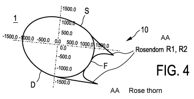
Figure 4 shows, for a rotor blade 1 of the preferred embodiment, a rose thorn
profile of a
rotor blade profile 10. The rotor blade profile in the hub region I, as a
thickness profile
1() with a relative thickness of greater than 45% and a trailing edge of
greater than 5%, has,
at the suction and the pressure side S, D, in each case one rose thorn in the
form of a
thorn-like extension R1, R2. The thorn depth measured from the trailing edge
lies below
25% and above a relative thickness of the trailing edge, specifically in
particular above
5%. The rotor blade profile is shown already with an angle of attack (with
twist), which, at
any rate in the region close to the hub of the hub region, may lie between 0
and 70 , in
particular between 0 and 45 , and in this case tends to increase.
Figure 5 shows the rotor blade profile of figure 4 with additional vortex
generators W1,
W2, wherein the vortex generators are arranged on the suction and the pressure
side S,
D.
Figure 6 shows a distribution of different profile geometries of a rotor blade
of an embod-
iment. In the rotor blade 1, profile thicknesses 2 and profile depths 3 are
illustrated sec-
tion by section. The rotor blade 1 has, at one end, the rotor blade root 4,
and, at the end
of her to therefrom, a connection region 5 for the attachment of a rotor blade
tip. At the
rotor blade root 4, the rotor blade has a large profile depth 3. In the
connection region 5,
the profile depth 3 is, by contrast, very much smaller. The profile depth
increases consid-
erably proceeding from the rotor blade root 4, which can also be referred to
as profile
root, as far as a central region II.
Figure 7 shows that, in the channel K of the blade profile between the suction-
side rose
thorn and the pressure-side rose thorn, that is to say in the channel between
the suction-
side and pressure-side thorn-like extensions R1, R2, a relatively stable
channel vortex W
in the direction of the suction side is formed. The channel vortex, which
rotates anticlock-
wise, draws air from the suction side S into the channel K between the suction-
side and
pressure-side thorn-like extensions R1, R2, and prevents a detachment of the
flow on the
suction side. The pressure-side flow at the pressure side D additionally
stabilizes the
CA 03010688 2018-07-05
- 14 -
channel vortex W. Together with the relatively stable channel vortex, the
blade profile in
the hub region I thus has a profile depth lengthened by the channel vortex,
such that a
longer streamline is formed; the profile depth of the blade profile is, as it
were, lengthened
by the stable channel vortex. This leads to improved lift values, for as long
as the channel
vortex is stable. This is however ensured by the suction-side and pressure-
side rose
thorns of the thorn-like extensions. Furthermore, the rotor blade profile of
figure 7 is
equipped with vortex generators, such that a detachment of an incident flow in
the
boundary surface does not occur prematurely. This leads to stable pressure
conditions
for the channel vortex in the channel between the suction-side and pressure-
side rows
thorns of the thorn-like extensions of the blade profile. Figure 7 shows a
flow around the
rotor blade with flows in the case of an angle of attack of 70 - the concept
of the invention
is however in no way restricted to such angles of attack, but is rather
directed more to the
less favorable situation of an angle of attack of 300. However, figure 7 shows
the basic
principle and the possibility of saving a considerable amount of material
through the use
of the rose thorns. The turbulence generators can also be smaller than shown;
the rose
thorns thus become relatively smaller.
Figure 8 shows, in (A), a coordinate illustration of the rose thorn profile of
figure 7 with an
associated flow profile (B); here, it is possible in particular to see the
formation of the
drawn-in flow, indicated in figure 7, as a stabilized vortex W between the
thorns R1, R2.
Figure 9 shows a side view of a rotor blade 900 of an embodiment over its
entire length I,
that is to say from 0% to 100%. The rotor blade 900 has, at one end, a rotor
blade root
904 and, at the end of the therefrom, a rotor blade tip 907. The rotor blade
tip 907 is
connected to the rest of the rotor blade at an attachment region 905. At the
rotor blade
root 904, the rotor blade has a large profile depth. By contrast, the profile
depth is very
much smaller in the attachment region 905 and at the rotor blade tip 907.
Proceeding
from the rotor blade root 904, which can also be referred to as profile root,
the profile
depth decreases considerably as far as a central region 906. In the central
region 906,
there may be provided a parting point (not illustrated here). From the central
region 906
to the attachment region 905, the profile depth is approximately constant.
The rotor blade 900 has a two-part form in the region of the rotor blade root
904. The
rotor blade 900 is thus composed of a main profile 909, on which, in the
region of the
rotor blade root 904, a further section 908 is arranged for the purposes of
increasing the
rotor blade depth of the rotor blade 900. The section 908 is in this case for
example
adhesively bonded to the main profile 909. Such a two-part form is easier to
handle
during transport to the erection site, and is easier to manufacture.
CA 03010688 2018-07-05
- 15 -
Furthermore, figure 9 shows a hub attachment region 910. By means of the hub
attach-
ment region 910, the rotor blade 900 is attached to the rotor hub.
Figure 10 shows a further side view of the rotor blade 900 of figure 9. It is
possible to see
the rotor blade 900 with the main profile 909, with the section 908 for
increasing the rotor
blade depth, the central region 906, the rotor blade root 904 and the hub
attachment
region 910, and also the attachment region 905 to the rotor blade tip 907. The
rotor blade
tip 907 is formed as a so-called winglets. In this way, vortices at the rotor
blade tip are
reduced.
In the detail of figure 9, the section 908 is shown as a trailing edge piece
with the channel
K between the suction-side and the pressure-side rose thorn R1, R2.
Altogether, howev-
er, the depth of the trailing edge piece is smaller because, owing to the
preferred stable
channel vortex formation, the effective relative profile thickness of the
blade profile in the
hub region is increased.
In the detail of figure 10, the trailing edge piece is shown, on the one hand,
in view A,
without a serrated form, and, on the other hand, in view B, with a serrated
form. Depend-
ing on requirements, it is possible in particular by means of a serrated form
or other flow-
stabilizing measures to assist the channel vortex formation and thus increase
the effec-
tive relative profile thickness of the blade profile in the hub region.
Figure 11 shows a preferred embodiment, which can be seen in the upper part,
as a first
modification with a trailing edge piece ¨ for example in the form of a
trailing edge box
which is fitted separately ¨ as already shown as section 908 in figure 9 and
figure 10.
The rotor blade 1, which is correspondingly shown with an profile depth
increased in the
hub region I, has been described in particular in conjunction with figure 9
and figure 10 ¨
with the trailing edge piece with thorn-like extension, that is to say as
section 908, the
depth of the trailing edge piece is, for similar lift and glide values,
smaller than in the case
of a trailing edge piece without thorn-like extension. The profile depth of a
rotor blade 1 of
said type can thus be relatively reduced owing to the abovementioned stable
channel
vortex formation, such that an effective relative profile thickness of the
blade profile in the
hub region can be increased. Since, owing to the preferred stable channel
vortex for-
mation, the effective relative profile thickness of the blade profile
increases in the hub
region, this is suitable preferably, but not imperatively, for the
implementation of a rotor
blade 1 as shown in figure 6.
CA 03010688 2018-07-05
- 16 -
Figure 11 also shows a further particular preferred embodiment as second
modification,
which is referred to here as a rotor blade 1'. In this second modification,
the thorn-like
extension is formed in the hub region "directly" at a trailing edge F of the
core of the rotor
blade, wherein the thorn-like extension R1, R2 remains below the dashed line
L'; the
dashed line L' thus forms the trailing edge of the thorn-like extension R1,
R2. The trailing
edge piece 908 of the rotor blade 1 is omitted in the case of the rotor blade
1'.
The profile depth of the rotor blade 1' is thus restricted to a region below
the dashed line
L'. The rotor blade 1' is thus formed with a considerably smaller profile
depth (chord
length) while nevertheless, as shown, maintaining considerable and
advantageous lift
and glide values. This leads to a very considerable reduction and thus
considerably
improved transportability of the rotor blade 1'.
The rotor blade 1' can be produced particularly efficiently in the hub region
I by virtue of
the thorn-like extension being attached, in particular only the thorn-like
extension (as in
this case in this embodiment shown in figure 12) being attached, to the core
as the
abovementioned thickness profile with a relative thickness of greater than
50%, in par-
ticular greater than 75% ¨ that is to say to the trailing edge of the core
with a relatively
large trailing edge thickness.
A substantially cylindrical or oval wound part with a thickness profile of an
advantageous
relative thickness of greater than 50%, in particular greater than 75%,
progresses from a
hub region remote from the hub 1.2 to a region close to the hub 1.1, as can be
clearly seen
for example in figure 13, to a cylindrical thickness profile of an
advantageous relative
thickness of up to 100% in the attachment region of the hub.
For the rotor blade 1', and also for the rotor blade 1, a parting point R is
provided, at
which the rotor blade 1, 1' is assembled in a longitudinal direction.
Figure 12 shows a three-dimensional illustration of a preferred embodiment of
a rotor
blade in the hub region (I), with a thorn-like extension visible in the hub
region, wherein,
in the hub region, in a first region close to the hub, the thickness profile
has the thorn-like
extension at its trailing edge, and also in a second region, specifically in
the hub region in
a second region remote from the hub, the thickness profile has the trailing
edge a flat
trailing edge the thorn-like extension.
The rotor blade 1' is, for its hub region I, illustrated in figure 12 in a
perspective view with
a parting point R widened in a bead-like manner. The perspective illustration
of the rotor
blade 1' in figure 12 shows that the thickness profile in the hub region 1 is
formed as a
CA 03010688 2018-07-05
- 17 -
substantially elliptical core 11' and then, developing in the longitudinal
direction toward
the hub, oval and then cylindrical core 11', which is formed as a wound part
WT, as is
correspondingly indicated in figure 13.
A first thorn-like extension R1 is attached at the suction side S of the core
11', and a
second thorn-like extension R2 is attached at the pressure side D of the core
11', specifi-
cally in each case at the trailing edge F of said core. In this way, a channel
K which is
visible in figure 12 is formed, specifically at the trailing edge F between
the suction-side
thorn-like extension R1 and the pressure-side thorn-like extension R2, with a
substantially
flat base, formed by the trailing edge F, between the first and the second
thorn-like ex-
tension RI, R2.
Figure 13 shows, in conjunction with figure 12 and figure 11, for the cross
sections A-A
and B-B and C-C shown in figure 11, in the views (A), (B) and (C) of figure
13, the corre-
sponding profiles with a relative thickness of greater than 50% and then
greater than 75%
and finally practically 100% of the rotor blade 1' toward the hub ¨ in this
regard, a calcu-
lated distribution of flow speeds is shown. The flow speeds are illustrated as
shading, and
make it possible to see the channel vortex W in the channel K between the
thorn-like
extensions R1, R2 on the wound part WT ¨ this will be referred to further
below.
It is possible from the profiles of figure 13, in the views (A), (B) and (C),
to see that a
relative and/or absolute profile thickness 2, which is defined as a ratio of
profile thickness
2 to profile depth 3 (see figure 6), increases from a rotor blade tip 5, 7 to
a rotor blade
root 4; specifically, a relative profile thickness of initially below 45%
increases to above
50%, then increases to above 75%, up to a relative profile thickness of
practically 100%
of a cylindrical blade attachment at the rotor blade root 4 or hub
it can also be seen that the flat base of a channel K ¨ that is to say formed
by the practi-
cally flat trailing edge F of the rotor blade 1' ¨ is outwardly arched between
the first and
the second thorn-like extension R1, R2 in the case of a profile close to the
hub (as illus-
trated in view (A) of figure 13). Thus, whereas it is the case in the region
close to the hub
1.1 that the base is outwardly arched, said base is relatively flat in a
central hub region I
(illustrated in this case in view (B) of figure 13), and said base is inwardly
arched in a
region remote from the hub 1.2 of the hub region 1 (as can be seen in view (C)
of figure
13).
It can also be seen from figure 12 that the first and the second thorn-like
extension R1,
R2 at the trailing edge F are arranged at a circumferential angle of below 60
, specifically
in this case at a circumferential angle al, a2, shown in figure 12, of
approximately 45 .
CA 03010688 2018-07-05
- 18 -
The circumferential angle al , a2 of the thorn-like extensions R1, R2 is in
this case meas-
ured proceeding from a profile axis (profile chord A of the profile of the
rotor blade 1').
The circumferential angle al at the suction side S of the first thorn-like
extension R1 at
the trailing edge F now runs at a substantially fixed circumferential angle al
in the direc-
tion of the tip region. At the pressure side D, the circumferential angle a2,
as can be seen
in figure 12, for the second thorn-like extension R2 at the trailing edge F
decreases in the
direction of the tip region III. That is to say, the thorn-like extensions R1,
R2 converge on
one another, in order to merge at the intersection point T at the end of the
hub region I.
This corresponds approximately to a position at which the circumferential
angle for both
rose thorn profiles R1, R2 lies at approximately 00 or above, possibly at the
fixed circum-
ferential angle al.
As can be seen in figure 12, provision is made whereby, in the hub region I,
in a first
region, specifically in a region close to the hub 1.1 in the hub region I, the
thickness profile
has a relatively large first relative thickness and the thorn-like extension
at its flat trailing
edge. Provision is furthermore made whereby, in the hub region 1, in a second
region, in
particular in a region remote from the hub 1.2 in the hub region I, the
trailing edge of the
thickness profile has a pointed trailing edge without a thorn-like extension,
or a flat trailing
edge with a second, relatively small relative thickness and likewise with the
thorn-like
extension.
The pressure-side thorn-like extension R2 follows, as it were, the twist of
the rotor blade
I'; that is to say, the decreasing angle of attack y in the direction of the
tip region III ¨ this
was already visible from figure 6, and is shown clearly once again in figure
12. In a cen-
tral region, which is only partially illustrated here, the profile of the
rotor blade already has
a pointed trailing edge, which is formed from the converging first and second
thorn is R1,
R2 of the suction side and pressure side. In other words, the rotor blade l'
has a truncat-
ed trailing edge (figure 3) which is formed from the converging first and
second thorns of
the suction side and pressure side, wherein a relative trailing edge thickness
lies in the
region of 5% or below ¨ in a tip region which is not illustrated here, the
profile of the rotor
blade has a pointed trailing edge (figure 2).
It can also be seen that, in the region close to the hub 1.1 of the hub region
I, at the suc-
tion side, the first thorn-like extension R1 at the trailing edge F has a
relative thorn depth
which is smaller than a relative thorn depth of the second thorn-like
extension R2 at the
trailing edge F at the pressure side D of the rotor blade 1. It can also be
seen from figure
12 that, in the region close to the hub of the hub region I, at the pressure
side, the second
CA 03010688 2018-07-05
- 19 -
thorn-like extension R2 at the trailing edge has an orientation with a more
pronounced
inclination toward the pressure side than an orientation of the first thorn-
like extension R1
at the trailing edge at the suction side S. This can be seen from the fact
that the orienta-
tion angle 81 for the first thorn-like extension R1 is greater than the
orientation angle 82
for the second thorn-like extension R2.
Furthermore, for the second thorn-like extension R2 at the trailing edge F, a
profile,
arched toward the pressure side D, of a pressure-side underside R2u of the
thorn-like
extension R2 is provided. That is to say, for the pressure-side underside U of
the second
thorn-like extension R2, a profile arched toward the pressure side D with an
increasing
curvature is provided. The lift effect that can thus be achieved can
additionally be further
intensified by means of a so-called arched lip; for example a spoiler lip or a
Gurney flat or
the like, as can be seen in view (C) of figure 13. This leads to a boosting of
the pressure
on the pressure side D, and thus to increased lift values.
It can be seen that this embodiment as illustrated in figure 12 and figure 11
as a rotor
blade 1' realizes flow speeds in the region of the channel K which lie between
0.01 Ma
and 0.1 Ma, and is thus particularly effective in supporting and stabilizing a
channel
vortex formation W.
A glide ratio (lift/drag ratio), as illustrated for views (A), (B) and (C) in
figures 13 and
figure 14 (that is to say for the cross sections A-A, B-B and C-C of figure
11), is still
relatively high; specifically, in the case of angles of attack y of up to 5
for the section A-
A, said glide ratio still assumes values of at least 2.5, for section B-B,
said glide ratio still
assumes values of up to 8, and for the section C-C, said glide ratio still
assumes values
of up to even 10. These are glide ratios which can ultimately be realized
owing to the
"effective" increase of the profile depth owing to the stabilized channel
vortex W, as can
be seen from figure 13, even though the structural profile depth of the rotor
blade 1' is
considerably smaller.
In other words, as can be seen in figure 13, the "effective" profile depth of
the rotor blade
1' is lengthened beyond the actual trailing edge F (as it were owing to the
channel vor-
tex); in particular, it is lengthened by at least 20% but at least 50% ¨ or
beyond the trail-
ing edge of the thorn-like extensions R1, R2 by up to 20% but at least up to
10%.
This advantageous effect is particularly pronounced as a result of the fact
that a flow
separation is first evident downstream of the vortex W, whereas the flow does
not detach
from a structural trailing edge of the thorn-like extension.