Note: Descriptions are shown in the official language in which they were submitted.
CA 03010978 2018-07-10
WO 2017/161441 PCT/CA2017/000067
PROCESSES FOR EFFECTING HYDROCARBON PRODUCTION FROM
RESERVOIRS HAVING A LOW PERMEABILITY ZONE BY COOLING AND
HEATING
FIELD
[0001] The present disclosure relates to improvements in production of
hydrocarbon-
comprising material from hydrocarbon reservoirs having low permeability zones.
BACKGROUND
[0002] Thermal enhanced oil recovery methods are used to recover bitumen
and heavy oil
from hydrocarbon reservoirs. The most dominant thermal enhanced oil recovery
method being
applied to oil sands reservoirs is steam-assisted gravity drainage ("SAGD").
However, SAGD
performance suffers when oil sands reservoirs include zones of reduced
permeability, such as
shale barriers.
SUMMARY
[0003] In one aspect, there is provided a process for producing hydrocarbon
material from a
reservoir, comprising: cooling at least a portion of a low permeability zone
within the reservoir
with effect that water, disposed within the low permeability zone, freezes and
expands, with
effect that one or more flow paths are formed through the low permeability
zone; mobilizing
hydrocarbon material within the reservoir such that the mobilized hydrocarbon
material is
conducted through the low permeability zone via the one or more flow paths;
and after the
conduction of the mobilized hydrocarbon material through the low permeability
zone via the
one or more flow paths, producing the mobilized hydrocarbon material.
[0004] In another aspect, there is provided a process for producing
hydrocarbon material
from a reservoir, comprising: cooling at least a portion of a low permeability
zone within the
reservoir such that stress is reduced within the at least a portion of a low
permeability zone;
pressurizing the cooled portion of the low permeability zone with effect that
one or more flow
paths are formed through the low permeability zone; mobilizing hydrocarbon
material within
the reservoir such that the mobilized hydrocarbon material is conducted
through the low
permeability zone via the one or more flow paths; and after the conduction of
the mobilized
CA 03010978 2018-07-10
WO 2017/161441 PCT/CA2017/000067
hydrocarbon material through the low permeability zone via the one or more
flow paths,
producing the mobilized hydrocarbon material.
[0005] In another aspect, there is provided a process for producing
hydrocarbon material
from a reservoir, comprising: heating at least a portion of a low permeability
zone within the
reservoir with effect that water, disposed within the low permeability zone,
vaporizes and
effects formation of one or more flow paths through the low permeability zone;
mobilizing
hydrocarbon material within the reservoir such that the mobilized hydrocarbon
material is
conducted through the low petineability zone via the one or more flow paths;
and after the
conduction of the mobilized hydrocarbon material through the low permeability
zone via the
one or more flow paths, producing the mobilized hydrocarbon material.
[0006] In another aspect, there is provided a process for producing
hydrocarbon material
from a reservoir, comprising: heating at least a portion of a low permeability
zone within the
reservoir; reducing pressure of the at least a portion of a low permeability
zone, with effect that
water, disposed within the low permeability zone, vaporizes and effects
formation of one or
more flow paths through the low permeability zone; mobilizing hydrocarbon
material within the
reservoir such that the mobilized hydrocarbon material is conducted through
the low
permeability zone via the one or more flow paths; and after the conduction of
the mobilized
hydrocarbon material through the low permeability zone via the one or more
flow paths,
producing the mobilized hydrocarbon material.
[0007] In another aspect, there is provided a process for producing
hydrocarbon material
from a reservoir, comprising: cooling at least a portion of a low permeability
zone within the
reservoir such that stress is reduced within the at least a portion of a low
permeability zone;
pressurizing the cooled portion of the low permeability zone with effect that
one or more flow
paths are formed through the low permeability zone; and receiving hydrocarbon
material, that is
conducted through the one or more of the flow paths, within a production well;
and producing
the received hydrocarbon material.
2
CA 03010978 2018-07-10
WO 2017/161441 PCT/CA2017/000067
BRIEF DESCRIPTION OF DRAWINGS
[0008] Embodiments will now be described, by way of example only, with
reference to the
attached figures, wherein:
[0009] Figure 1 is a schematic illustration of one side of an embodiment of
a system for
implementing steam assisted gravity drainage ("SAGD") for producing
hydrocarbon material
from a reservoir having a low permeability zone disposed between horizontal
sections of a well
pair;
[0010] Figure 2 is a schematic illustration of one side of another
embodiment of a system
for implementing steam assisted gravity drainage ("SAGD") for producing
hydrocarbon
material from a reservoir having a low permeability zone disposed between
horizontal sections
of a well pair, illustrating a dimensional attribute of the low permeability
zone;
[0011] Figure 3 is a schematic illustration of an end view of the
embodiment illustrated in
Figure 2;
[0012] Figure 4 is a schematic illustration of an end view of another
embodiment of a
system having two well pairs for implementing steam assisted gravity drainage
("SAGD") for
producing hydrocarbon material from a reservoir having a low permeability zone
disposed
between horizontal sections of one of the well pairs, illustrating a
dimensional attribute of the
low permeability zone;
[0013] Figure 5 is a schematic illustration of one side of an embodiment of
a system for
implementing steam assisted gravity drainage ("SAGD") for producing
hydrocarbon material
from a reservoir having a low permeability zone disposed above a horizontal
section of the
injection well of a well pair;
[0014] Figure 6 is a schematic illustration of one side of another
embodiment of a system
for implementing steam assisted gravity drainage ("SAGD") for producing
hydrocarbon
material from a reservoir having a low permeability zone disposed above a
horizontal section of
the injection well of a well pair, illustrating a dimensional attribute of the
low peinieability
zone;
3
CA 03010978 2018-07-10
WO 2017/161441 PCT/CA2017/000067
[0015] Figure 7 is a schematic illustration of an end view of the
embodiment illustrated in
Figure 6;
[0016] Figure 8 is a schematic illustration of an end view of another
embodiment of a
system for implementing steam assisted gravity drainage ("SAGD") for producing
hydrocarbon
material from a reservoir having a low permeability zone disposed above a
horizontal section of
the injection well of a well pair, illustrating a dimensional attribute of the
low permeability
zone; and
[0017] Figure 9 is a schematic illustration of a steam chamber that has
developed by
operating a SAGD process using the system illustrated in any one of Figures 1
to 8.
DETAILED DESCRIPTION
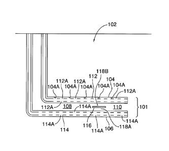
[0018] The present disclosure relates to use of a production-initiating
fluid for effecting
production of hydrocarbon material from a hydrocarbon-containing reservoir 102
disposed
within a subterranean formation below the earth's surface 12.
[0019] As used herein, the following terms have the following meanings:
[0020] "Hydrocarbon" is an organic compound consisting primarily of
hydrogen and
carbon, and, in some instances, may also contain heteroatoms such as sulfur,
nitrogen and
oxygen.
[0021] "Hydrocarbon material" is material that consists of one or more
hydrocarbons.
[0022] "Heavy hydrocarbon material" is material that consists of one or
more heavy
hydrocarbons. A heavy hydrocarbon is a hydrocarbon that, at conditions
existing with the
hydrocarbon-containing reservoir, has a an API gravity of less than 26 degrees
and a viscosity
of greater than 20,000 centipoise. An exemplary heavy hydrocarbon material is
bitumen.
[0023] A well, or sections of a well, can be characterized as "vertical" or
"horizontal" even
though the actual axial orientation can vary from true vertical or true
horizontal, and even
though the axial path can tend to "corkscrew" or otherwise vary. The term
"horizontal-, when
used to describe a section of a wellbore, refers to a horizontal or highly
deviated wellbore
4
CA 03010978 2018-07-10
WO 2017/161441 PCT/CA2017/000067
section as understood in the art, such as, for example, a wellbore section
having a longitudinal
axis that is between 70 and 110 degrees from vertical.
[0024] The meaning of the terms "above" and "below" are not intended to be
limited to
mean, respectively, "directly above" and "directly below", but are rather
intended to define the
elevation of one or more elements relative to the elevation of one or more
other elements.
[0025] Referring to Figures 1 to 8, there is provided a system 100 for
carrying out a process
for producing hydrocarbon material from a hydrocarbon-containing reservoir
102. In some
embodiments, for example, the hydrocarbon-containing reservoir includes an oil
sands
reservoir, and the hydrocarbon material includes heavy hydrocarbon material,
such as bitumen.
[0026] The system 100 includes a well pair 101. The well pair 101 includes
a pair of wells
104, 106. Each one of the wells 104, 106, independently, includes a respective
horizontal
section. The well 104 functions as a injection well and the well 106 functions
as a production
well. The injection well 104 injects production-initiating fluid to effect
production of the
hydrocarbon material via the production well 106.
[0027] In some embodiments, for example, a production-initiating fluid is
injected via an
injection string 112 that is disposed within the injection well 104, and the
produced fluid is
produced via a production string 114 that is disposed within the production
well 106.
[0028] In some embodiments, for example, the injection string 112 includes
a plurality of
ports 112A for injecting production-initiating fluid, that is being conducted
by the injection
string, into the reservoir 102 at a plurality of injection points 104A within
the reservoir 102. In
some embodiments, for example, the plurality of injection points 104A are
disposed along a
reservoir interface 102A that defines the interface between the injection well
104 and the
reservoir 102. In some embodiments, for example, the ports 112A are defined
within a slotted
liner of the injection string 112. In some embodiments, for example, the ports
112A are
disposed within a horizontal section of the injection well 104.
[0029] In some embodiments, for example, the production string 114 includes
a plurality of
ports 114A for receiving fluid that is being conducted within the reservoir
102 in response to the
injection of the production-initiating fluid. In some embodiments, for
example, the ports 114A
CA 03010978 2018-07-10
WO 2017/161441 PCT/CA2017/000067
are defined within a slotted liner of the production string 114. In some
embodiments, for
example, the ports 114A are disposed within a horizontal section of the
production well 106.
[0030] A hydrocarbon production process may be implemented via the well
pair 101, so
long as fluid communication is effected between the wells 104, 106 via a
communication zone
110 (i.e. fluid is conductible (for example, by flowing)) such that the
injected production-
initiating fluid effects mobilization of the hydrocarbon material within the
reservoir, and the
mobilized hydrocarbon material is conducted to the production well 106 via the
communication
zone 110 for production via the production well 106. The conduction of the
hydrocarbon
material to the production well 106 is effected in response to an applied
driving force (for
example, application of a fluid pressure differential, or gravity, or both),
In some embodiments,
for example, the production-initiating fluid functions as a drive fluid
effecting conduction (or
transport) of hydrocarbon material to the production well 106. In some
embodiments, for
example, the production-initiating fluid functions as a heat transfer fluid,
supplying heat to the
hydrocarbon material, such that viscosity of the hydrocarbon material is
sufficiently reduced (in
such state, the hydrocarbon material is said to be mobilized), such that the
hydrocarbon material
may be conducted to the production well 106 by a driving force, such as, for
example, a
pressure differential or gravity. In some embodiments, for example, the
production-initiating
fluid functions as both a drive fluid and a heating fluid. In some
embodiments, for example, the
hydrocarbon material is produced along with some of the injected production-
initiating fluid,
such as, for example, production-initiating fluid that has heated the
hydrocarbon material (as
described above) and has become condensed, such that fluid that is being
produced via the
production well includes hydrocarbon material and condensed production-
initiating fluid.
While the wells 104, 106 are disposed in fluid communication through the
communication zone
110, production-initiating fluid is injected into the reservoir 102 such that
the hydrocarbon
material is conducted to the well 106, via the communication zone 110, and
produced through
the well 106. In some embodiments, for example, the hydrocarbon material that
is received by
the well 106 is produced via the well 106 by artificial lift. In some
embodiments, for example,
the producing of the hydrocarbon material via the production well 106 is
effected while the
production-initiating fluid is being injected by the injection well 104. In
this respect, in some
embodiments, for example, the hydrocarbon production process is a continuous
process.
6
CA 03010978 2018-07-10
WO 2017/161441 PCT/CA2017/000067
[0031] In
some embodiments, for example, the hydrocarbon production process includes a
thermally-actuated gravity drainage-based hydrocarbon production process that
is implemented
via the well pair 101. In such embodiments, the horizontal section of the well
104 is vertically
spaced from the horizontal section of the well 106, such that the horizontal
section of the well
104 is disposed above the horizontal section of the well 106, such as, for
example, by at least
three (3) metres, such as, for example, by at least five (5) metres. In some
embodiments, for
example, the production-initiating fluid includes steam. A production phase
(i.e. when
hydrocarbon material is being produced via the well 106) of the thermally-
actuated gravity
drainage-based hydrocarbon production process occurs after the communication
zone 110 has
been established. The establishing of the communication zone 110 includes at
least the
establishing of interwell communication, through the interwell region 108,
between the wells
104, 106. "Interwell communication", in the context of a thermally-actuated
gravity drainage-
based hydrocarbon production process, describes a condition of the reservoir
which permits
hydrocarbon material within the reservoir 102, mobilized by heat supplied from
the injected
production-initiating fluid that is injected via the injection well 104, to be
conducted, by at least
gravity drainage, to the production well 106. In this respect, the interwell
communication is
established when the injected production-initiating fluid is able to
communicate heat to
hydrocarbon material within the reservoir such that the hydrocarbon material
is mobilized, and
the mobilized hydrocarbon material is then conducted, by at least gravity,
through the interwell
region 108, to the production well 106.
[0032] With
respect to thermally-actuated gravity drainage-based hydrocarbon production
processes being implemented via the well pair 101, in some of these
embodiments, for example,
initially, the reservoir 102 has relatively low fluid mobility (such as, for
example, due to the fact
that the hydrocarbon material within the reservoir 102 is highly viscous) such
that the
communication zone 110 is not present. In order to enable the injected
production-initiating
fluid (being injected through the injection well 104) to promote the
conduction of the reservoir
hydrocarbons, within the reservoir 102, to the production well 106, the
communication zone
110 must be established. This establishing of the communication zone 110
includes
establishing interwell communication between the wells 104, 106 through the
interwell region
108. By
establishing the interwell communication, the conduction of the mobilized
hydrocarbon material, through the interwell region 108, is enabled such that
the mobilized
7
CA 03010978 2018-07-10
WO 2017/161441 PCT/CA2017/000067
hydrocarbon material is collected within the production well 106. The
interwell
communication may be established during a "start-up" phase of the thermally-
actuated gravity
drainage-based hydrocarbon production process. In some embodiments, for
example, during
the start-up phase, the interwell region 108 is heated. In some embodiments,
for example, the
heat is supplied to the interwell region 108 by effecting circulation of a
start-up phase fluid
(such as steam, or a fluid including steam) in one or both of the wells 104,
106. The heat that is
supplied to the interwell region 108 heats the reservoir hydrocarbons within
the interwell region
108, thereby reducing the viscosity of the reservoir hydrocarbons. Eventually,
the interwell
region 108 becomes heated to a temperature such that the hydrocarbon material
is sufficiently
mobile (i.e. the hydrocarbon material has been "mobilized") for displacement
to the production
well 106 by at least gravity drainage. In this respect, eventually, sufficient
hydrocarbon
material becomes mobilized, such that this space (the interwell region 108),
previously occupied
by immobile, or substantially immobile, hydrocarbon material, is disposed to
communicate fluid
between the injection well 104 and the production well 106 in response to a
driving force, such
that at least hydrocarbon material is conductible through this space in
response to the driving
force. Upon the interwell region becoming disposed to communicate fluid
between the
injection well 104 and the production well 106 in response to a driving force,
such that at least
hydrocarbon material is conductible through this space in response to the
driving force, the
interwell communication, between the wells 104, 106, is said to have become
established. The
development of this interwell communication signals completion of the start-up
phase and
conversion to a production phase.
[0033] During
the production phase of a thermally-actuated gravity drainage-based
hydrocarbon production process, the communication zone 110 effects fluid
communication
between the production-initiating fluid, being injected through the injection
well 104, with
hydrocarbon material within the reservoir, such that the injected production-
initiating fluid is
conducted through the communication zone 110 and becomes disposed in heat
transfer
communication with hydrocarbon material within the reservoir such that the
hydrocarbon
material becomes heated. When sufficiently heated such that its viscosity
becomes sufficiently
reduced, the hydrocarbon material becomes mobilized, and, in this respect, the
hydrocarbon
material is able to be conducted, by at least gravity drainage (the conduction
may also, for
example, be promoted by a pressure differential that is established between
the injected
8
CA 03010978 2018-07-10
WO 2017/161441 PCT/CA2017/000067
production initiating fluid and the production well 106, which may also, in
some embodiments,
be characterized as a "drive process" mechanism), through the communication
zone 110, to the
production well 106, and subsequently produced from the production well 106 by
artificial lift,
such as by a pump. During the production phase, while the production-
initiating fluid is being
injected into the communication zone 110 via the injection well 104, as the
mobilized
hydrocarbon material drains to the production well 106, space previously
occupied by the
hydrocarbon material within the reservoir becomes occupied by the injected
production-
initiating fluid, thereby exposing a fresh hydrocarbon material surface for
receiving heat from
the production-initiating fluid (typically, by conduction). This repeated
cycle of heating,
mobilization, drainage, and establishment of heat transfer communication
between the
production-initiating fluid and a freshly exposed hydrocarbon material source
results in the
growth of the communication zone 110, with the freshly exposed hydrocarbon
material being
disposed along an edge of the communication zone 110. Referring to Figure 9,
in some
embodiments, for example, the communication zone 110 includes a "vapour
chamber". In some
embodiments, for example, the vapour chamber may also be referred to as a
"steam chamber".
In some embodiments, for example, the growth of the communication zone 110 is
upwardly,
laterally, or both, and, typically, extends above the horizontal section of
the injection well 104.
[0034] In
some embodiments, for example, where, in implementing the thermally-actuated
gravity drainage-based hydrocarbon production process, the production-
initiating fluid includes
steam, the process that is effecting this production is described as "steam-
assisted gravity
drainage" or "SAGD". In some embodiments, for example, the communication zone
110
includes a vapour chamber, such as, for example, a "steam chamber". During
SAGD, the
conduction of the mobilized hydrocarbon material to the production well 106 is
accompanied by
condensed steam (i.e. water), whose condensation is effected by at least heat
loss to the
hydrocarbon material (which effects the mobilization of the hydrocarbon
material).
[0035] In
some embodiments, for example, the reservoir includes a low peuneability zone.
The low permeability zone 116 is a zone whose absolute permeability is less
than 1000
millidarcies, such as, for example, less than 100 millidarcies, such as, for
example, less than 10
millidarcies.
9
CA 03010978 2018-07-10
WO 2017/161441 PCT/CA2017/000067
[0036] Examples of low permeability zones include baffles and barriers.
These include
shale, breccia, inclined heterolithic strata, mud, and mudstone.
[0037] In some embodiments, for example, the low permeability zone 116 has
a dimension
of at least 10 metres, such as, for example, 25 metres, such as, for example,
at least 35 metres.
In some embodiments, for example, the dimension is a width.
[0038] In some embodiments, for example, the low permeability zone 116 is
relatively thin,
and, in this respect, in some embodiments, for example, is characterized by a
maximum
thickness of less than 5 centimetres.
[0039] In some embodiments, for example, at least a continuous portion of
the low
permeability zone 116 is disposed within a horizontal plane within the
reservoir 102, wherein
the horizontal plane-disposed continuous portion of the low permeability zone
116 is
characterized by an area of at least 100 square metres.
[0040] In some embodiments, for example, the low permeability zone 116 is
disposed
between the horizontal sections of the wells 104, 106, such as, for example,
in the interwell
region 108.
[0041] Referring to Figures 2 and 3, in some embodiments, for example, at
least a
continuous portion of the low permeability zone 116 is disposed between the
horizontal sections
of the wells 104, 106, and the continuous portion has an axis "Al", and the
axis "Al" has a
length "LI" of at least 10 metres, such as, for example, at least 50 metres,
such as, for example,
at least 100 metres.
[0042] Referring to Figure 4, in some embodiments, for example, at least a
continuous
laterally-extending portion of the low permeability zone 116 is disposed
between the horizontal
sections of the wells 104, 106 and is also extending towards another well pair
201 and across at
least 1/3 of a spacing distance "SD" between the well pairs 101. 102. In some
embodiments, for
example, the at least a continuous laterally-extending portion of the low
permeability zone 116
extends from between the well pair 101 and towards the another well pair 201
by a distance
"Dl" of at least 25 metres, such as, for example, at least 35 metres.
CA 03010978 2018-07-10
WO 2017/161441 PCT/CA2017/000067
[0043] Referring to Figure 5, in some embodiments, for example, the low
permeability zone
116 is disposed above both of the horizontal sections of the wells 104, 106.
[0044] Referring to Figures 6 and 7, in some embodiments, for example, at
least a
continuous portion of the low permeability zone 116 includes an axis "A2", and
the axis "A2"
of the at least a continuous portion is disposed above, and in vertical
alignment with, a
longitudinal axis "A3" of the horizontal section of the well 104, and has a
length "L2" of at
least 10 metres, such as, for example, at least 50 metres, such as, for
example, at least 100
metres.
[0045] Referring to Figure 8, in some embodiments, for example, at least a
continuous
portion of the low permeability zone 116 is disposed above the horizontal
section of the well
104 and at a height "H", above the bottom of the reservoir, that is less than
50% of the total
height "TH" of the reservoir. In some embodiments, for example, at least a
continuous portion
of the low permeability zone 116 is disposed above the horizontal section of
the well 104 and at
a height "H" of less than 35 metres (such as, for example, less than 25
metres) above the bottom
of the reservoir.
[0046] There is provided a process for forming a flow path within a low
permeability zone
116, for effecting flow communication within the reservoir 102, via the flow
path, between a
communication-interfered zone 118A and a wellbore. The low permeability zone
116 is
disposed between the wellbore and the communication-interfered zone 118A. In
some
embodiment, for example, the low permeability zone 116 functions as an
impediment for
conduction of fluid material into and from the communication-interfered zone
118A and a
wellbore, and the flow communication effected by the flow path is intended to
enable such
conduction. In some embodiments, for example, the impediment includes an
impediment to a
vertical flow of fluid. In some embodiments, for example, the wellbore is
defined as an
injection well 104 of a SAGD system. In some embodiments, for example, the
wellbore is
defined as a production well 106 of a SAGD system.
[0047] In some embodiments, for example, the process for forming a flow
path within a low
permeability zone 116 includes cooling of at least a portion of the low
permeability zone 116.
11
CA 03010978 2018-07-10
WO 2017/161441 PCT/CA2017/000067
[0048] In some embodiments, for example, the cooling of the at least a
portion of the low
permeability zone 116 is such that the rate of decrease of temperature within
the at least a
portion of the low permeability zone 116 is at least one (1) degrees Celsius
per hour, such as,
for example, at least two (2) degrees Celsius per hour.
[0049] In some embodiments, for example, the cooling is effected by
injecting a cold fluid
(i.e. a fluid having a temperature that is less than the temperature of the
low permeability zone)
with effect that the injected cold fluid becomes disposed in thermal
communication with the low
permeability zone 116. In some embodiments, for example, the injecting
includes circulating a
cold fluid within one or both of the wells 104, 106, in which case, the
cooling is effected by
conduction of heat from the subterranean formation between the injection well
104 and the low
permeability zone 116. In some embodiments, for example, the low permeability
zone 116 is
spaced apart from at least one of the wells 104, 106, through which the cold
fluid is being
circulated, by a minimum distance of less than 15 metres, such as, for
example, less than 10
metres.
[0050] In some embodiments, for example, the temperature of the cold fluid
is less than
minus 50 degrees Celsius.
[0051] In some embodiments, for example, the rate of cooling of the at
least a portion of the
low permeability zone 116 is at least 0.03 degrees Celsius per metre per day,
such as, for
example, 0.04 degrees Celsius per metre per day.
[0052] In some embodiments, for example, the cold fluid includes any one,
or any
combination of, the fluids selected from the group consisting of: liquid
nitrogen, liquid CO2 and
liquid hydrocarbon solvents such as propane, butane, and natural gas
condensate.
[0053] In some embodiments, for example, the cooling of the low
permeability zone 116 is
effected prior to the production phase.. In some embodiments, for example, the
cooling of the
low permeability zone 116 is effected prior to the heating of the interwell
region 108 during the
SAGD start-up phase. In this respect, in some embodiments, for example, after
the cooling, a
SAGD start-up phase is implemented, followed by a SAGD production phase.
12
CA 03010978 2018-07-10
WO 2017/161441 PCT/CA2017/000067
[0054] Cooling of the low permeability zone 116 relieves stresses within
the low
permeability zone 116. Because the heat sink is within a well through which
cold fluid is being
conducted, as a necessary incident, such cooling also relieves the stresses in
an intermediate
region of the subterranean formation, between a well through which cold fluid
is being
conducted (e.g. the injection well) 104 and the low permeability zone 116,
thereby conditioning
the low permeability zone 116, as well as the intermediate formation region
between the well
and the low permeability zone 116, such that both of the intermediate
formation region and the
low permeability zone 116 are disposed for crack formation at lower applied
pressures.
[0055] In some embodiments, for example, the cooling of the low
peimeability zone 116 is
with effect that a temperature decrease is effected to at least a portion of
the low permeability
zone 116, and with effect that one or more cracks are formed within the low
permeability zone
116.
[0056] In some embodiments, for example, the cooling of the low
permeability zone 116 is
with effect that a temperature decrease is effected to at least a portion of
the low permeability
zone 116 to below a predetermined temperature. In some embodiments, for
example, the
cooling of the low permeability zone 116 is such that at least a portion of
the low permeability
zone 116 becomes disposed at a temperature that is below the freezing point of
water at the
pressure within the low permeability zone 116.
[0057] In this respect, in some embodiments, for example, the cooling of
the low
permeability zone is with effect that at least a portion of the low
permeability zone 116 becomes
disposed at a temperature that is below the freezing point of water at the
pressure within the low
permeability zone and effects freezing of water within the at least a portion
of the low
permeability zone. Because water expands upon freezing, one or more cracks are
formed in the
low permeability zone 116 in response to the freezing of the water, thereby
defining one or
more flow paths for conducting of fluid material within the low permeability
zone, such as, for
example, conducting of a heating fluid (such as, for example, a start-up phase
fluid or a
production-initiating fluid), or conducting of mobilized hydrocarbon material.
In some
embodiments, for example, the entirety of the low permeability zone 116
becomes disposed at a
13
CA 03010978 2018-07-10
WO 2017/161441 PCT/CA2017/000067
temperature that is below the freezing point of water at the pressure within
the low permeability
zone, in response to the cooling.
[0058] In some embodiments, for example, the process for forming a flow
path within a low
permeability zone 116 includes cooling the low permeability zone 116 (such as,
for example, in
accordance with any one of the embodiments, as above-described), and, after
the low
permeability zone 116 has been cooled, pressurizing the cooled low
permeability zone 116. As
explained above, the cooling of the low permeability zone 116 relieves
stresses within the low
permeability zone 116, as well as an intermediate fon-nation region between
the well (which is
functioning as a heat sink) and the low permeability zone 116, thereby
conditioning both of the
intermediate formation region and the low permeability zone 116 for crack
formation at lower
applied pressures. Co-operatively, pressurized material is injected into the
reservoir 102, for
pressurizing the cooled low permeability zone 116, and thereby effecting
foimation of one or
more cracks within the cooled low permeability zone 116.
[0059] In some embodiments, for example, the pressurized material is
supplied via a
wellbore, such as the injection well 104, or the production well 106, or both,
and injected into
the reservoir 102 for pressurizing the low permeability zone 116. In some
embodiments, for
example, the pressurizing is with effect that the low permeability zone
becomes disposed at a
pressure of at least original reservoir pressure, such as, for example, at
least 105% of original
reservoir pressure, such as, for example, at least 110% of original reservoir
pressure. In some of
these embodiments, for example, the pressurizing is with effect that the low
permeability zone
116 becomes disposed at a pressure of up to the maximum allowable pressure of
the reservoir
102 (the pressure that is determined to maintain integrity of the cap rock
above the reservoir)
[0060] In some embodiments, for example, the pressurized material is
injected at an
injection pressure of between the original reservoir pressure and the maximum
allowable
pressure of the reservoir 102. In some embodiments, for example, the injection
pressure is the
lowest pressure (above the original reservoir pressure) at which formation
parting is achievable
following cooling of the reservoir 102 (such as, for example, in close
proximity to a well, such
as the injection well 104), such cooling resulting in a reduction in reservoir
effective stress from
such cooling.
14
CA 03010978 2018-07-10
WO 2017/161441 PCT/CA2017/000067
[0061] In
some embodiments, for example, the duration of the injecting of the
pressurized
material is at least two (2) minutes, such as, for example, at least five (5)
minutes, such as, for
example, at least 20 minutes, such as for example, at least one (1) hour, such
as, for example, at
least two (2) hours, such as, for example, at least five (5) hours, such as,
for example, at least
one (1) day, such, as for example, at least two (2) days, such as, for
example, at least five (5)
days.
[0062] In
some embodiments, for example, the pressurized material includes a fluid. In
some embodiments, for example, the pressurized material includes a liquid
including water. In
some embodiments, for example, the liquid includes water and chemical
additives. In other
embodiments, for example, the pressurized material is a slurry including
water, proppant, and
chemical additives.
Exemplary chemical additives include acids, sodium chloride,
polyacrylamide, ethylene glycol, borate salts, sodium and potassium
carbonates, glutaraldehyde,
guar gum and other water soluble gels, citric acid, and isopropanol. In some
embodiments, for
example, the pressurized material is supplied to effect hydraulic fracturing
of the reservoir.
[0063] In
some embodiments, for example, the process for forming a flow path within a
low
permeability zone 116 includes heating the low permeability zone 116.
[0064] In
some of these embodiments, for example, the heating is effected by circulating
a
heating fluid (i.e. a fluid having a temperature that is greater than the
temperature of the low
permeability zone) within one or both of the wells 104, 106 (such as, for
example, during the
SAGD start-up phase), with effect that the circulated heating fluid becomes
disposed in thermal
communication with the low permeability zone 116.
[0065] In
some embodiments, for example, the heating fluid includes steam, and may also
include steam admixed with a solvent that is soluble within the hydrocarbon
material that is
disposed within the reservoir 102. In some embodiments, for example, the
heating fluid
includes glycerine. In
some embodiments, for example, the heating fluid includes
diethanolamine (DEA). In some embodiments, for example, the heating fluid is
the start-up
phase fluid. In some embodiments, for example, the low permeability zone 116
is spaced apart
from at least one of the wells 104, 106, through which the heating fluid is
being circulated, by a
minimum distance of less than 15 metres, such as, for example, less than 10
metres.
CA 03010978 2018-07-10
WO 2017/161441 PCT/CA2017/000067
[0066] In
some embodiments, for example, the heating is effected by injecting (such as,
for
example, during the SAGD production phase) a heating fluid (i.e. a fluid
having a temperature
that is greater than the temperature of the low permeability zone) into the
reservoir 102 with
effect that the injected heating fluid becomes disposed in thermal
communication with the low
peuneability zone 116. In
some of these embodiments, for example, the thermal
communication is established by mobilizing hydrocarbon material between the
injection well
104 and the low peimeability zone 116 (such as by, for example, implementing
the production
phase of the thermally-actuated gravity drainage-based process, as above-
described) such that
the mobilized hydrocarbon material is conducted to the production well 106,
and the space
previously occupied by immobile, or substantially immobile, hydrocarbon
material, is disposed
to conduct the injected heating fluid from one or both of the wells 104, 106,
such that the
injected heating fluid becomes disposed in thermal communication with the low
permeability
zone 116. In some embodiments, for example, the heating fluid includes steam,
and may also
include steam admixed with a solvent that is soluble within the hydrocarbon
material that is
disposed within the reservoir. In some embodiments, for example, the heating
fluid is the
production-initiating fluid. In some embodiments, for example, the low
permeability zone 116
is spaced apart from at least one of the wells 104, 106, through which the
heating fluid is being
injected, by a minimum distance of less than 15 metres, such as, for example,
less than 10
metres.
[0067] In
some embodiments, for example, the heating of the low permeability zone 116
includes heating that is effected by electrical heating. In some embodiments,
for example, the
electrical heating can be effected by a resistive electric heater or by
electromagnetic energy
propagation into the formation. In some embodiments, for example, the
electrical heating is
effected by an electrical heater disposed in one or both of the wells 104,
106. In some
embodiments, for example, the low permeability zone 116 is spaced apart from
at least one of
the wells 104, 106, through which the electrical heater is disposed, by a
minimum distance of
less than 15 metres, such as, for example, less than 10 metres.
[0068] In
some embodiments, for example, the heating of the low permeability zone 116
includes heating that is effected by in-situ combustion. An exemplary in-situ
combustion
process is SAGDOXTM.
16
CA 03010978 2018-07-10
WO 2017/161441 PCT/CA2017/000067
[0069] In some embodiments, for example, the heating of the low
permeability zone 116 is
effected prior to the SAGD production phase. In some embodiments, for example,
the heating
of the low permeability zone 116 is effected after hydrocarbon material has
been produced
during the SAGD production phase.
[0070] In some embodiments, for example, the heating of the low
permeability zone 116 is
effected prior to the heating of the interwell region 108 during the SAGD
start-up phase.
[0071] In some embodiments, for example, the heating of the low
permeability zone 116 is
effected during the heating of the interwell region 108 during the SAGD start-
up phase, in
which case, in some embodiments, for example, the heating fluid includes the
start-up phase
fluid.
100721 In some embodiments, for example, the heating of the low
permeability zone 116 is
effected during the SAGD production phase, in which case, in some embodiments,
for example,
the heating fluid includes production-initiating fluid.
[0073] In some embodiments, for example, the heating of the low
permeability zone 116 is
with effect that a temperature increase is effected to at least a portion of
the low permeability
zone 116, and with effect that one or more cracks are formed within the low
permeability zone
116. In some embodiments, for example, the heating of the low permeability
zone 116 is with
effect that a temperature increase is effected to at least a portion of the
low permeability zone
116 to above a predetermined temperature. In some embodiments, for example,
the heating of
the low permeability zone 116 is such that at least a portion of the low
permeability zone 116
becomes disposed at a temperature of at least steam temperature at the
pressure within the low
permeability zone 116. By heating the low permeability zone 116 such that at
least a portion of
the low permeability zone 116 becomes disposed at a temperature of at least
steam temperature
at the pressure within the low permeability zone 116, water within the low
permeability zone
116 is vaporized, expands, and effects crack formation within the low
permeability zone.
[0074] In some embodiments, for example, the rate of heating necessary to
effect
mechanical failure within the low permeability zone 116, and consequent crack
formation, is
dependent on the permeability of the low permeability zone 116: the lower the
permeability, the
17
CA 03010978 2018-07-10
WO 2017/161441 PCT/CA2017/000067
low the rate of heating that is required. This is because the fluid (in some
embodiments, for
example, a fluid including water), being vaporized within the low permeability
zone 116, will
escape from the low permeability zone 116 at a rate that is fast enough such
that pressure
increase within the low permeability zone 116 is not sufficient to effect
mechanical failure and
consequent crack formation. In this respect, with zones of lower permeability
(such as for low
permeability zones with permeability less than 5 millidarcies), a faster rate
of heating is
required to enable a pressure increase within the low permeability zone 116
that is sufficient to
effect mechanical failure and consequent crack formation. In some embodiments,
for example,
the heating of the at least a portion of the low permeability zone 116 is such
that the rate of
increase of temperature within the at least a portion of the low permeability
zone 116 is at least
one (1) degrees Celsius per hour, such as, for example, at least two (2)
degrees Celsius per hour.
[0075] In some embodiments, for example, the duration of the heating is at
least one (1)
minute, such as, for example, at least two (2) minutes, such as, for example,
at least five (5)
minutes, such as, for example, at least ten (10) minutes, such as, for
example, at least one (1)
hour, such as, for example, at least five (5) hours, such as, for example, at
least one (1) day,
such as, for example, at least two (2) days, such as, for example, at least
five (5) days. In some
embodiments, for example, the duration of the heating of the at least a
portion of the low
permeability zone 116 is at least 30 days. In some embodiments, for example,
the duration of
the heating of the at least a portion of the low permeability zone 116 is
between 30 days and 90
days. The duration depends on the distance of the at least a portion of the
low permeability
zone 116 from the heat source.
[0076] In some embodiments, for example, the process for forming a flow
path within a low
permeability zone 116 includes heating the low permeability zone 116 (such as,
for example, in
accordance with any one of the embodiments, as above-described), and, after
the low
permeability zone 116 has been heated, effecting a reduction in pressure of
the heated low
permeability zone 116. The heating of at least a portion of the low
permeability zone 116, and
after the heating, the effecting a reduction in pressure of the low
permeability zone 116, co-
operate with effect that water within the low permeability zone 116 is
vaporized, expands, and
effects crack formation within the low permeability zone 116.
18
CA 03010978 2018-07-10
WO 2017/161441 PCT/CA2017/000067
[0077] The rate of heating necessary to cause mechanical failure of the low
permeability
zone and the formation of cracks is dependent on the permeability of the low
permeability zone,
the lower the permeability, the lower the rate of heating required. This is
because the fluid being
vaporized within the low permeability zone, in some instances water, will
escape from the low
permeability zone and not cause the pressure to increase enough to result in
formation of cracks.
For low permeability zones with permeability less than 5 millidarcies, a rate
of heating of at
least one degree Celsius per hour is required, and rates higher, such as 2
C/hr would be
preferred. In some embodiments, for example, the heating of the at least a
portion of the low
permeability zone 116 is such that the rate of increase of temperature within
the at least a
portion of the low permeability zone 116 is at least one (1) degrees Celsius
per hour, such as,
for example, at least two (2) degrees Celsius per hour. The temperature of the
low permeability
zone must reach the saturated steam temperature at the reservoir pressure so
that liquid water
contained within the low permeability zone will begin to vaporize immediately
as the pressure
is reduced.
[0078] In some embodiments, for example, the heating of at least a portion
of the low
permeability zone 116 is with effect that the temperature of the at least a
portion of the low
permeability zone 116 is between 200 degrees Celsius and 240 degrees Celsius.
[0079] In some embodiments, for example, the duration of the heating is at
least one (1)
minute, such as, for example, at least two (2) minutes, such as, for example,
at least five (5)
minutes, such as, for example, at least ten (10) minutes, such as, for
example, at least one (1)
hour, such as, for example, at least five (5) hours, such as, for example, at
least one (1) day,
such as, for example, at least two (2) days, such as, for example, at least
five (5) days. In some
embodiments, for example, the duration of the heating of the at least a
portion of the low
permeability zone 116 is at least 30 days. In some embodiments, for example,
the duration of
the heating of the at least a portion of the low permeability zone 116 is
between 30 days and 90
days. The duration depends on the distance of the at least a portion of the
low permeability
zone 116 from the heat source.
[0080] After the temperature increase has been effected by the heating, a
reduction in
pressure of the low permeability zone 116 is effected. The reduction in
pressure is with effect
19
CA 03010978 2018-07-10
WO 2017/161441 PCT/CA2017/000067
that vaporized water is produced, and such vaporized water is derived from
water within the low
permeability zone 116. The produced vaporized water is disposed at a
sufficient pressure to
induce sufficient stress within the rock of the low peluteability zone 116 to
effect formation of
one or more cracks within the low permeability zone 116. In some embodiments,
for example,
the rate at which the pressure reduction is effected is a function of the
permeability of the low
permeability zone 116.
[0081] In some embodiments, for example, the reduction in pressure is at
least 50 psi over a
period of time of 48 hours, such as, for example, at least 100 psi over a
period of time of 48
hours.
[0082] When the heating is effected by the circulating of heating fluid
within one or both of
the wells 104, 106 (such as, for example, during the SAGD start-up phase), in
some of these
embodiments, for example, the reduction in pressure of the low permeability
zone 116 is
effected by suspending the circulation of the heating fluid.
[0083] When the heating is effected by electrical heating, in some of these
embodiments,
for example, the reduction in pressure of the low permeability zone 116 is
effected by producing
hydrocarbon material via one or both of the wells 104, 106.
[0084] When the heating is effected by injecting of heating fluid into the
reservoir 102, in
some of these embodiments, for example, the reduction in pressure of the low
permeability zone
116 is effected by suspending supplying of the heating fluid into the
communication zone 110.
[0085] When the heating is effected by injecting (such as, for example, via
the injection
well 104) of heating fluid (such as, for example, production-initiating fluid)
into the reservoir
102 (such as, for example, the communication zone 110), while producing fluid
(in some
embodiments, for example, the fluid includes hydrocarbon material) from the
reservoir 102
(such as, for example, from the communication zone 110, and via the well 106),
in some of
these embodiments, for example, the reduction in pressure of the low
permeability zone 116 is
effected by increasing the rate of production of fluid from the reservoir 102,
while continuing
the injecting of the heating fluid to the reservoir 102 at the same or
substantially the same molar
rate.
CA 03010978 2018-07-10
WO 2017/161441 PCT/CA2017/000067
[0086] When the heating is effected by injecting (such as, for example, via
the injection
well 104) of heating fluid (such as, for example, production-initiating fluid)
into the reservoir
102 (such as, for example, the communication zone 110), while producing fluid
(in some
embodiments, for example, the fluid includes hydrocarbon material) from the
reservoir 102
(such as, for example, from the communication zone 110, and via the well 106),
in some of
these embodiments, for example, the reduction in pressure of the low
permeability zone 116 is
effected by continuing production of fluid from the reservoir 102 at the same
or substantially
the same rate, while decreasing the rate at which the heating fluid is
supplied to the reservoir
102.
[0087] When the heating is effected by injecting (such as, for example, via
the injection
well 104) of heating fluid (such as, for example, production-initiating fluid)
into the reservoir
102 (such as, for example, the communication zone 110), while producing fluid
(in some
embodiments, for example, the fluid includes hydrocarbon material) from the
reservoir 102
(such as, for example, from the communication zone 110, and via the well 106),
in some of
these embodiments, for example, the reduction in pressure of the low
permeability zone 116 is
effected by, co-operatively, modulating the rate at which the heating fluid is
supplied to the
reservoir 102 and modulating the rate at which fluid is produced from the
reservoir 102. In this
respect, the modulating of the rate at which the heating fluid is supplied to
the reservoir 102 and
the modulating the rate at which fluid is produced from the reservoir 102 co-
operate with effect
that the reduction in pressure of the low permeability zone 116 is effected.
[0088] In some embodiments, for example, the process for forming a flow
path within a low
permeability zone 116 is effected in response to detection of the low
permeability zone 116. In
some of these embodiments, for example, such detection is effected only after
the SAGD start-
up phase has commenced and prior to the SAGD production phase. In some
embodiments, for
example, such detection is effected only after the SAGD production phase has
commencted. In
some embodiments, for example, the detection of the low permeability zone 116
is inferred
from temperature conformance data, drilling logs, or petrophysical logs.
[0089] In some embodiments, for example, the low permeability zone 116 is
disposed
within the interwell region 108 (between the horizontal sections of the wells
104, 106), with
21
CA 03010978 2018-07-10
WO 2017/161441 PCT/CA2017/000067
effect that a communication-interfered zone 118A is disposed between the low
permeability
zone 116 and the horizontal section of the production well 106, and a
communication-interfered
zone 118B is disposed between the low permeability zone 116 and the horizontal
section of the
injection well 104. The low permeability zone 116 is disposed for at least
interfering with fluid
communication, and, in some embodiments, for blocking flow communication,
between: (i) the
injection well 104 and the communication-interfered zone 118A, and (ii) the
production well
106 and the communication-interfered zone 118B. In this respect, the low
permeability zone
116 is disposed for at least interfering with, and in some embodiments,
blocking, conduction of
fluid material between: (i) the injection well 104 and the communication-
interfered zone 118A,
and (ii) the production well 106 and the communication-interfered zone 118B,
and, therefore,
functions as a vertical impediment to such conduction.
[0090] During the start-up phase, the low permeability zone 116 is disposed
for at least
interfering with, and in some embodiments, blocking, conduction of heat from
start-up phase
fluid, that is being circulated by the wells 104, 106, to the communication-
interfered zones
118A, 118B, thereby at least interfering with mobilization of the hydrocarbon
material within
the communication-interfered zones 118A, 118B by the start-up phase fluid.
Also during the
start-up phase, the low permeability zone 116 is disposed for at least
interfering with, and in
some embodiments, blocking, conduction of mobilized hydrocarbon material from
the
communication-interfered zone 118B to the production well 106, and thereby
impeding the
development of a flow-communicating space (i.e. interwell communication), that
has been
previously occupied by immobile, or substantially immobile, hydrocarbon
material, for
communicating flow between the injection well 104 and the production well 106
in response to
a driving force, such that at least hydrocarbon material is conductible
through this space in
response to the driving force (i.e. interwell communication). During the
production phase, the
low permeability zone 116 is disposed for at least interfering with, and in
some embodiments,
blocking, conduction of the mobilized hydrocarbon material that is draining
towards the
production well 106 from the vapour (e.g. steam) chamber, via the
communication-interfered
zone 118B, and thereby interfering with production.
[0091] The one or more cracks that are formed, in accordance with any one
of the processes
described above, effect flow communication through the low permeability zone
116, enabling
22
CA 03010978 2018-07-10
WO 2017/161441 PCT/CA2017/000067
conduction of fluid material within the interwell region 108 via the low
permeability zone 116.
In this respect, in some embodiments, for example, the crack formation is with
effect that there
is an increase in absolute permeability of the low permeability zone 116 by at
least 200%, such
as, for example, by at least 2500%, such as, for example, at least 5000%.
[0092] In this respect, the one or more cracks can effect: (i) conduction
of start-up phase
fluid from the well 104 to the communication-interfered zone 118A, or (ii)
conduction of start-
up phase fluid from the well 106 to the communication-interfered zone 118B, or
both of (i) and
(ii), thereby facilitating heating of one or both of the communication-
interfered zones 118A,
118B, during the start-up phase. Also, the one or more cracks can effect
conduction of
mobilized hydrocarbon material from the communication-interfered zone 118B to
the well 106,
during the start-up phase, thereby facilitating the establishment of interwell
communication, as
above-described, Further, the one or more cracks can effect conduction of
mobilized
hydrocarbons from the communication-interfered zone 118B to the well 106
during the
production phase, thereby facilitating an increased rate of production of
hydrocarbon material
from the reservoir.
[0093] In some embodiments, for example, the low permeability zone 116 is
disposed above
the horizontal sections of the injection well 104, and, therefore, above the
horizontal section of
the production well (see Figure 5), with effect that the low permeability zone
116 is disposed
between a communication-interfered zone 1182 and the horizontal section of the
production
well 106, and also between the communication interfered zone 1182 and the
horizontal section
of the injection well 104, In this respect, the low permeability zone 116 is
disposed for at least
interfering with flow communication, and, in some embodiments, for blocking
flow
communication, between: (i) the injection well 104 and the communication-
interfered zone
1182, and (ii) the production well 106 and the communication-interfered zone
1182. In this
respect, the low permeability zone 116 is disposed for at least interferes
with, and in some
embodiments, blocking, conduction of fluid material between: (i) the injection
well 104 and the
communication-interfered zone 1182, and (ii) the production well 106 and the
communication-
interfered zone 1182, and, therefore, functions as a vertical impediment to
such conduction.
23
[0094] During
the production phase. the low permeability zone 116 is disposed for at least
interfering with, and in some embodiments, blocking, conduction of the
production-initiating
fluid to the communication-interfered zone 1182 (disposed above the low
permeability zone
116) for effecting heating and mobilization of hydrocarbon material disposed
within the
communication-interfered zone 1182. In this respect, in some embodiments, for
example, the
low permeability zone 116 functions as an impediment to the growth of the
vapor (or steam)
chamber. As well, even if the production-initiating fluid is able to migrate
above the low
permeability zone 116 and into the communication-interfered zone 1182, the low
permeability
zone 116 is disposed for at least interfering with, and in some embodiments,
blocking,
conduction of the mobilized hydrocarbon material that is draining from the
communication-
interfered zone 1182 (e.g. the steam chamber) to the production well 106, and
thereby
interfering with production.
[0095] In this
respect, the one or more cracks, that are formed in accordance with any
one of the processes described above, can effect conduction of the production-
initiating fluid
from the injection well 104 to the communication-interfered zone 1182 during
the production
phase, thereby facilitating mobilization of the hydrocarbon material within
the reservoir, and
enabling growth of the vapour (e.g. steam) chamber. Also, the one or more
cracks can effect
conduction of the mobilized hydrocarbons from the communication-interfered
zone 1182 to the
production well 106 during the production phase, thereby facilitating an
increased rate of
production of hydrocarbon material from the reservoir.
[0096] In the
above description, for purposes of explanation, numerous details are set
forth in order to provide a thorough understanding of the present disclosure.
However, it will be
apparent to one skilled in the art that these specific details are not
required in order to practice
the present disclosure. Although
certain dimensions and materials are described for
implementing the disclosed example embodiments, other suitable dimensions
and/or materials
may be used within the scope of this disclosure. All such modifications and
variations,
including all suitable current and future changes in technology, are believed
to be within the
sphere and scope of the present disclosure.
CAN_DMS' \130403332\1 24
CA 3010978 2019-11-07