Note: Descriptions are shown in the official language in which they were submitted.
CA 03011324 2018-07-12
WO 2017/122071
PCT/IB2016/057969
Cladding for a modular frame structure
Description
The present invention relates to a cladding of a modular
frame structure, of the type used for assembling even
complex buildings. Under modular frame a complex frame is
meant, obtained by means of interconnecting several
module frames identifying an outer wall of the building,
which has to be cladded, as well as a plurality of
intermediate floors and partitions which give shape and
function to the building.
International patent application N. WO 2004/033,809 Al
describes a cladding formed by joining two panels spaced-
apart by a plate with a Z-like profile, with a peripheral
frame constituted by closing beams, which then are used
for assembly with a supporting frame.
European patent application N. 2,213,807 Al describes a
modular wall formed by spacing elements and several
overlapped panels.
European patent application N. 2,444,565 Al describes a
connection system for panels arranged on a building
façade, wherein the framework includes a metallic rigid
element which is used for connecting the plates and which
gives the structure the required resistance.
Even British patent application N. 2,524,025 describes an
assembly structure for panels, comprising a framework
constituted by elements fixed therebetween, to provide
passage channels for electrical services.
International patent application N. WO 2010/139,681 A
describes a cladding system with a supporting element
fastened to a bearing wall sustaining an outer panel so
as to determine an air gap, with additional intermediate
panels arranged to form additional air gaps.
US patent N. 6,134,860 A relates to a frame for
prefabricated structures constituted by coupled walls
CA 03011324 2018-07-12
WO 2017/122071
PCT/IB2016/057969
implementing a support for surface boardings.
US patent N. 6,256,960 B1 describes a prefabricated
building with framework-like peripheral elements which
are used to position the outer walls.
US patent N. 2010/0095621 A describes an insulating panel
provided with fixed joints for assembling additional
panels.
US patent application N. 2012/0247043 describes a
building modular system wherein frame peripheral elements
define passages in which panels are inserted constituted
by an outer foil, an inner foil, and an insulating
intermediate element.
British application N. GB 2,412,385 A describes a
cladding according to the preamble of the enclosed claim
1, however without intermediate claddings between
different module frames.
Even International patent application N. WO 98/56,999 Al
and French patent application N. FR 2,951,213 Al describe
details inherent to the claddings of module frames.
Therefore, the state of art offers very diversified
solutions, but they hardly adapt to a modular frame
formed by beams and by knots of metallic nature, which
can be used in climatic areas very different therebetween
and which however has to guarantee an insulation adequate
to the reference climatic area, without thermal bridges
causing not correctly insulated areas, with a consequent
energy loss.
The technical problem underlying the present invention is
to provide a cladding of a modular frame structure
allowing to obviate the drawback mentioned with reference
to the known art.
Such problem is solved by a cladding of a modular frame
structure as defined in the annexed claim 1.
The main advantage of the cladding according to the
- 2 -
CA 03011324 2018-07-12
WO 2017/122071
PCT/IB2016/057969
present invention lies in allowing, the assembly
procedure being equal, a considerable freedom in
selecting thicknesses and materials which adapt to a
frame with beams and metallic joints, by obtaining an
overall homogeneous and optimum insulation.
The present invention will be described hereinafter
according to a preferred embodiment thereof, provided by
way of example and not with limiting purposes by
referring to the enclosed drawings wherein:
* figure 1 shows an axonometric view of a complex frame
resulting from assembling several module frames of the
structure, which is suitable to receive a cladding
according to the present invention, wherein the
mentioned dimensions represent purely indicative and
not limiting values;
* figure 2 shows a detail of a module frame of figure 1,
with an exploded view illustrating the scheme for
assembling a cladding according to the present
invention;
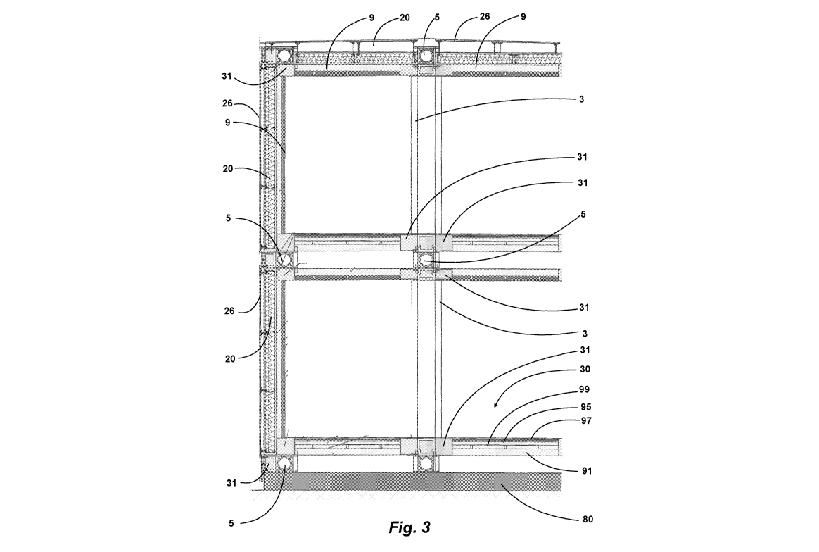
* figure 3 shows a vertical section of a complex
building illustrating both the complex frame of figure
1 and the cladding of the present invention;
* figure 4 shows a first enlarged detail of the cladding
of figure 3 in cross section;
* figure 5 shows a horizontal and partial section of the
cladding of figure 3;
* figure 6 shows a front view of the cladding of figure
3;
* figure 7 shows a second enlarged detail of the
cladding of figure 3 in cross section; and
* figure 8 shows a third enlarged detail of the cladding
of figure 3 in horizontal section.
By referring to figure 1, a complex frame of a modular
- 3 -
CA 03011324 2018-07-12
WO 2017/122071
PCT/IB2016/057969
building structure is designated with 1; it is
constituted by a certain number of module frames which
has a substantially parallelepiped-like shape and are
identified by the longitudinal beams 2, by the vertical
beams 3 and by the transversal beams 4.
Under parallelepiped, herein a straight parallelepiped
with rectangular faces is meant. Each module frame has
sizes allowing it to fall within the shape of a container
which can be transported by ordinary route, in case
loaded on the platform of an articulated vehicle, without
requiring a special transportation to move it from the
assembly site to the production site. A building module
then will correspond to each module frame, the building
module comprising the related claddings which will be
described hereinafter, and which can be assembled at
works, before the transportation to the laying site.
Each module frame has then angles wherein the
longitudinal, vertical and transversal beams 2, 3, 4
join. At such angles, the complex frame 1 comprises a
plurality of connecting knots 5 joining module frames
adjacent laterally on the same horizontal or vertical
plane, on the lower side or upper side on staggered
planes, or providing for the connection of the module
frames to a suitably arranged flat basement 80, or to a
not represented roof structure.
In case of adjacent module frames, they could be faced at
a longitudinal, vertical, upper or lower wall; otherwise,
in case of frames on staggered planes, they will have in
common an edge with two beams of the same type faced one
onto the other one.
Therefore, the shapes of each knot 5 change according to
the knot position, in particular each knot 5 should be
capable of providing for the mutual connection of a
number of module frame varying from one to eight and
thereof with basement 80.
- 4 -
CA 03011324 2018-07-12
WO 2017/122071
PCT/IB2016/057969
Generally, each knot 5 has a box-like structure with a
cubic and hollow parallelepiped-like shaped inner core 6,
formed by six walls faced two by two, each wall with a
circular opening so that they form respective channels
opened according to orthogonal axes X, Y and Z. Such
channels are opened, and the core inside provides a space
for passing through a channel or from a channel to the
other one.
The core could be made of a suitable material, for
example steel, preferably in one single piece and with
adequate thicknesses, so as to have the resistance
required for any design stress.
Furthermore, at each opening, the core 6 comprises a
corresponding supporting plate 7, for a total of six
supporting plates, parallel or orthogonal therebetween
two by two; in particular, the plates 7 of openings one
in front of the other one are parallel therebetween, and
the plates 7 of openings on adjacent plates are
orthogonal therebetween (figure 2).
Even the supporting plates could be made of suitable
material, in case in one single piece with the core 6, or
by means of welding of pieces.
Each supporting plate 7, if it extends beyond the plane
defined by an adjacent plate 7, defines therewith an
angular or side rest for a module frame angle.
By referring to figure 2, on an angle of the core 6 the
plates 7 extend beyond the two adjacent plates and
viceversa, by determining an angular rest formed by three
supporting plates 7 which form an angular space with
three resting walls.
Otherwise, at an edge of the core 6, two supporting
plates 7 can extend one beyond the other one and
viceversa, by forming a side rest formed by two L-like
positioned plate ends.
- 5 -
CA 03011324 2018-07-12
WO 2017/122071
PCT/IB2016/057969
In case a supporting plate 7 is not crossed by any of the
adjacent plates, it forms a resting plane which can be
connected to a basement or a roof (figure 2).
The shape of the knots 5 then allows not only to connect
adjacent module frames, but to space apart them one from
the other one. This determines two substantially combined
effects:
1. the overall sizes of the complex frame obtained by
assembling module frames will be larger than the sum
of the sizes of the single module frames; and
2. the distance between each module frame could allow,
together with the presence of the above-mentioned
channels in each knot 5, to arrange easily through
plants of electric, water nature (mains water, white
water, waste water, heating, refrigeration), air
conditioning plants, service tubes, alarm plants and
so on.
The first one of said effects allows to make each pre-
assembled module capable of being transported in a simple
way, as a usual container, and then to obtain a building
the overall sizes thereof would not be otherwise
compatible with normal transportation systems.
To this regard, the previously described angular rests
will be useful to receive the angles of each module
frame. Each angle will include a box-like connecting
element 8, formed by two or three walls connected
therebetween, which will be in contact with the
respective rest.
Advantageously, the frame beams have a L-like section
with the inner angle facing towards the inner space of
the module frame, to provide a support to the edges of
the inner panels 9 which will be described hereinafter
with greater detail.
The L-like beams, as well as the connecting elements 8,
could be made of suitable material, for example a folded
- 6 -
CA 03011324 2018-07-12
WO 2017/122071
PCT/IB2016/057969
or forged steel plate, or obtained by welding.
Each module, although formed by a frame which repeats
module by module, could assume very different shapes, but
it will include, at the walls forming the outer surface
of a complex building, outer paddings which could be
adapted to the climatic area of interest.
At the outer surface of the complex frame 1, the rests
arranged by the knots 5 could receive respective stopper-
like elements 10, for closing the opening faced outwards,
and framework elements 11 extending from a knot to the
other one and which will be used to support a cladding
panel 20. They will be described hereinafter with greater
details.
In this way, on the same outer wall, each so-obtained
framework would provide a different cladding, so as to
obtain different compositions.
It is to be noted that the above-mentioned stopper-like
elements and the framework elements have the task,
together with the panels 20, to close the outer surfaces
of the building, but even to implement a seal preventing
the air from entering the intermediate spaces between the
module frames 10, acting as thermal and acoustic
insulation and even for fireproofing purposes.
Such seal can be implemented thanks to self-expanding
belts and gaskets, arranged on the edges of the stopper-
like elements and of the framework elements.
The above-described structure obtained by assembling the
knots 5 with the module frames further allows to obtain
an adequate resistance to earthquake motions according to
the existing rules.
Each module frame 10 could include elements for
reinforcing the structure thereof. In particular, the
section of the beams 2, 3, 4 could be of box-like type;
the beams could be connected by vertical struts arranged
- 7 -
CA 03011324 2018-07-12
WO 2017/122071
PCT/IB2016/057969
on the vertical faces, or angular brace assemblies or
additional diagonal beams, or even transversal currents
on any face.
By referring to figures 3 to 8, the above-mentioned
claddings will be now described in greater detail.
In particular, the outer panel 20 comprises a box-like
reinforcement 21 made of wood or steel; inside, the
reinforcement 21 comprises angular elements 22 for
assembling the walls constituting the reinforcement,
which thus results to be closed. Inside, the
reinforcement 21 has a filler 23 which could be selected
in relation to the use climatic area.
For example, such filler 23 could comprise panels made of
wood fibre with variable density, selected based upon the
climatic area.
The filler will be included in a casing made of cloth or
paper to guarantee the air seal and the thermohygrometric
equilibrium of the filler 23.
The reinforcement 21 defines an outer face and an inner
face of the outer panel 20. On the inner face, the panel
comprises a compensation foil 24 made of compressible
material, which is suitable to be rested on an inner
panel 9.
The compressibility of the foil 24 guarantees a perfect
adhesion to the inner panel and the assembly clearance
compensation. The material of the compensation foil 24
can be cork or other material suitable to compensate a
possible clearance and the thickness of the plate which
constitutes the beam, for example a thermoplastic
material such as neoprene.
On the outer face, the outer panel 20 comprises a
plurality of fastening pins 25 infixed in the wall of the
reinforcement 21 through the angular elements 22, which
are stiff and made of metallic material, thus by offering
- 8 -
CA 03011324 2018-07-12
WO 2017/122071
PCT/IB2016/057969
the required structural support.
A flat element of outer finishing 26 can be assembled to
the fastening pins 21 existing at each angle of the outer
panel 20, which flat element forms an empty air gap 27
between it and outer face of the outer panel 20.
For the above-mentioned assembly, the fastening pin 25 is
equipped with L-like connecting elements 28, equipped
with suitable slotted holes for engaging a bolting 29
made of steel.
The flat element 26 can be constituted by a panel of any
nature: for example a panel made of treated wood, steel,
aluminium, a stratified layer made of glass or other
transparent or semi-transparent material, a sheet of
compressed concrete, a plate made of natural or
artificial stone (marble etc.), a photovoltaic module.
By referring to figure 6, the outer panel 20 can be
constituted by a plurality of panel-like elements 40
arranged edge against edge to form a more extended plane,
with an overall size to constitute a cladding for a whole
wall of module frame (figure 6); this assembling can be
implemented by fixing therebetween the end angular
elements 22 of each panel-like element 30 through the
respective reinforcement 21.
The inner panel 9 instead comprises the overlapping of a
pair of layers: a first bearing layer 91, which for
example can be made of wood, in particular of multi-
layered wood, and which is facing outwards; and a second
insulating thermal layer 92, for example a layer made of
a vegetable fibre such as linen, which is facing inwards.
On the inner face of the inner panel 9, then on the
second layer 92, there is a barrier 93 for the air seal
and to keep a thermohygrometric equilibrium of
conventional type, and in case a layer of plaster fibre
94.
- 9 -
CA 03011324 2018-07-12
WO 2017/122071
PCT/IB2016/057969
The same type of inner panel 9 can be used for the
ceiling of each inner environment (figure 3), whereas the
floors, designated with 30, will comprise, too, a first
bearing layer 91, still made of multi-layered wood,
facing downwards, as well as a plurality of insulating
layers 95 which can include foam material of vitreous
type (ex. expanded perlite), vegetable fibres (fibres
made of wood, cellulose, an air gap 99 between the
bearing layer and the insulating layers, and, of course,
a coating 97 for floors on the surface exposed to
trampling.
In the insulating layers 95 and in the air gap 99 ducts
or pipes related to plants integrated in the floor can be
provided, for example ducts for the hot water of a floor
heating, ducts for electrical cables, alarm systems and
so on.
By referring to the complex frame 1 resulting from
assembling the module frames, the horizontal edges, both
those at the basement and the roof, and those
corresponding to the inner floors, the cladding comprises
first box-like elements arranged at the conjunction of
the inner panels 9 and of the floors 30.
The first box-like elements 31 comprise a box made of
steel 32 with a filler 36 which comprises an insulating
material, for example a foam material such as expanded
perlite (figure 8).
Even the vertical edges of the complex frame comprise a
second box-like element 33 (figure 8) analogous to the
previous one, arranged at the respective inner panels 9.
At last, at the vertical beams 3 and the horizontal beams
4 arranged on the exposed faces of the complex frame 1,
the cladding comprises third box-like elements 34 which,
differently from the previous ones, comprise a box made
of wood 35 and a filler analogous to the previous one
(figures 7 and 8).
-10-
CA 03011324 2018-07-12
WO 2017/122071
PCT/IB2016/057969
The above-mentioned box-like elements can be opened, to
allow screwing the beams of the module frame to the knot,
once the box is empty. Once completed this assembling
phase, the box is closed and filled up with a filler 36,
which is even heat insulating and fireproofing agent.
It is to be noted that pins 25, analogous to those
already described, can be fastened to the box made of
wood 35, which pins support a beam cover 37 acting as
joint between the flat elements of outer finishing 26,
with snap insulating connections 38 arranged at the
respective edges (figure 7).
The third box-like elements 34 then constitute the
stoppers 10, for closing the openings of the joints 5
faced outwards, and the framework elements 11 of figure
2.
With the above-described arrangement, it is possible
implementing an outer cladding of a complex frame, thus
by forming a complex building, almost suitable to any
climatic area: it is sufficient selecting suitable
insulating materials and suitable thicknesses without
intervening on the frame.
Furthermore, whatever the thicknesses and the materials
selected to adequate the cladding to the climatic area
are, the inner sizes of the module frame remain the same,
so that it is possible planning different types of module
frame, equipped with inner panels and floors, without the
design being influenced in any way by the target climatic
area.
In the same way, the widest selection freedom remains, as
far as the outer boarding is concerned, which could or
could not participate in the overall thermal insulation,
or otherwise it could be destined to decorations or
finishings of any type or to the implementation of
photovoltaic panels.
The above-described components will be treated in order
-11-
CA 03011324 2018-07-12
WO 2017/122071
PCT/IB2016/057969
to have fireproofing, anti-intumescent features, and to
be protected from corrosion.
To the above-described cladding of a modular frame
structure a person skilled in the art, in order to
satisfy additional and contingent needs, could introduce
several additional modifications and variants, all
however comprised within the protection scope of the
present invention, as defined by the enclosed claims.
-12-