Note: Descriptions are shown in the official language in which they were submitted.
-1 -
CARTRIDGE FOR THE PREPARATION OF BEVERAGES
The present disclosure relates to cartridges for the preparation of beverages
and which
contain one or more ingredients for the preparation of beverages.
Background of the Disclosure
Domestic filter coffee machines have been widely available since the 1960s.
Domestic
coffee machines have developed significantly since the introduction of the
first filter machines and
are now essential pieces of kitchen equipment in many households. Some such
machines
dispense individual servings of a beverage directly into a drinking
receptacle, and derive the
beverage from a bulk supply of beverage ingredient or from individual packages
of beverage
ingredient such as pods, pads or cartridges. In the following specification,
such packages will be
referenced by the general term cartridges. Machines which use such cartridges
eliminate the
need for cleaning and can enable the user to make a selection of beverages. An
example of one
system using such cartridges is described in EP-A-1440903. The beverages are
formed from
brewing, mixing, dissolving or suspending the beverage ingredients in water.
For example, for
coffee beverages, heated water is forced through the cartridges to form the
extracted solution.
The use of cartridges in such machines has become increasingly popular due to
their
convenience and the quality of the beverage produced.
To allow a user to produce a full range of beverages in the home it is not
only necessary
to provide means for brewing high quality beverages such as filter coffee and
tea, it is also
necessary to provide the user with means for producing foamed beverages or
beverage
components. This may be, for example to make beverages such as cappuccino.
Traditionally
foamed milk has been produced in coffee shops by using a steam wand to direct
a steam jet into
a reservoir of liquid milk. This is still the primary method of producing
foamed milk in a commercial
environment. However, it is inconvenient to use steam jet equipment in the
home since it can be
dangerous if not used correctly and can also be difficult to clean. This is
particularly
disadvantageous for equipment used with milk which requires thorough cleaning
to prevent
contamination.
An example of a cartridge for a domestic beverage machine which is suitable
for
producing foamed milk from a concentrated liquid milk ingredient is known from
EP-A-1716055.
Foamed milk is produced from the cartridge by causing air to become entrained
in a milk stream
produced when water is mixed with the concentrated liquid milk ingredient
contained within the
cartridge. This is achieved by passing the beverage so formed through an
eductor within the
cartridge. The eductor comprises an aperture forming a constriction in the
flow path which is
CA 3011614 2018-07-17
- 2 -
arranged to produce a jet of the beverage and a consequent reduction in the
pressure of the
beverage. The jet of beverage exits the constriction and passes over an air
inlet whilst still at a
sub-atmospheric pressure causing air to become entrained in the beverage
thereby creating a
foamed beverage. Foamed milk produced from such cartridges allows coffee shop
style
beverages, such as cappuccino, to be readily produced in the home without the
need for
potentially dangerous, and difficult to clean, steam wand equipment.
Foamed beverages may also be produced from cartridges of this type containing
soluble
and powdered beverage ingredients, for example chocolate powder for a hot
chocolate beverage
or milk powder for a cappuccino-type beverage. However, there are a number of
particular
problems in using these cartridges for soluble, powdered and liquid beverage
ingredients.
It is necessary to adequately mix the beverage ingredient with water injected
into the
cartridge to provide a uniform beverage containing the desired amount of
beverage ingredient.
Inadequate mixing may result in some beverage ingredient remaining in the
chamber or in
coagulates of beverage ingredient forming in the beverage. In addition,
coagulates of this type
may block the constriction, preventing flow of the beverage through the
constriction to form a jet.
This may cause an undesirable back-pressure in the cartridge behind the
constriction, resulting in
splitting or other failure of the cartridge and/or preventing proper
functioning of the eductor by
hindering the production of the jet of beverage. It should also be appreciated
that the soluble
beverage mass may contain a minority of insoluble material (as found in
chocolate powder) or
large particles of soluble beverage ingredients (milk powder particles, for
example) which may not
fully dissolve in the water. These particles may likewise function to block
the flow constriction.
For these reasons, it is necessary to manage the flow of water within the
cartridge to
ensure proper mixing and pressure distribution and foaming of the beverage.
Accordingly, there is a desire for a beverage cartridge which ensures adequate
mixing of
the beverage ingredients, ensures proper water flow with in the cartridge and
prevents
undesirable levels of back pressure when using a flow constriction to foam the
beverage.
It will be understood that by the term "cartridge" as used herein is meant a
capsule, pod,
package, or container which contains one or more beverage ingredients in the
manner described
and is suitable for use with a beverage preparation machine. The cartridge may
comprise a single
component or an equivalent of multiple components. Preferably the cartridge is
adapted to
produce an individual serving of beverage. The cartridge may be rigid, semi-
rigid or flexible. The
inlet and outlet of the cartridge may be open or require opening in use by,
for example, piercing.
CA 3011614 2018-07-17
- 3 -
In the following description the terms "upper" and "lower" and equivalents
will be used to
describe the relational positioning of features of the disclosure. The terms
"upper" and "lower" and
equivalents should be understood to refer to the cartridge (or other
components) in its normal
orientation for insertion into a beverage preparation machine and subsequent
dispensing. In
particular, "upper" and "lower" refer, respectively, to relative positions
nearer or further from a
closed top 29 of the cartridge. In addition, the terms "inner" and "outer" and
equivalents will be
used to describe the relational positioning of features of the disclosure. The
terms "inner" and
"outer" and equivalents should be understood to refer to relative positions in
the cartridge (or
other components) being, respectively, nearer or further from a centre or
major axis of the
cartridge 1 (or other component).
Summary of the Disclosure
In a first aspect of the disclosure there is provided a cartridge for
preparation of a
beverage, the cartridge being sealed prior to use and containing one or more
beverage
ingredients, the cartridge being suitable to receive in use an aqueous medium
which may be
brought into contact with the one or more beverage ingredients to produce a
beverage which may
be output from the cartridge,
the cartridge comprising:
- a body defining a beverage ingredient chamber containing the one
or more beverage
ingredients;
- a first filter defining an exit from the beverage ingredient
chamber;
- a second filter downstream of, and spaced apart from, the first
filter; and
- a flow constriction downstream of the second filter,
such that in use beverage produced from the one or more beverage ingredients
passes,
in order, through the first filter, the second filter and the flow
constriction.
In the present disclosure, reference to "one or more beverage ingredients" and
"beverage
ingredient(s)" is intended to refer to one or more ingredients suitable for
forming a beverage. The
"one or more beverage ingredients" / "beverage ingredient(s)" may comprise a
single substance
or may comprise a beverage composition comprising two or more substances.
Unless explicitly
required by the context, references to "beverage ingredient" in the singular
are intended to include
the plural and vice versa.
The first filter may comprise a first filter wall and the second filter may
comprise a second
filter wall.
The first filter and the second filter may each comprise a rigid element
having a plurality
of filtering apertures located therein.
The first filter may extend around the second filter.
CA 3011614 2018-07-17
- 4 -
The first filter and the second filter may be arranged concentrically.
The first filter may comprise a first tubular member having a plurality of
first filtering
apertures located therein and the second filter may comprise a second tubular
member having a
plurality of second filtering apertures located therein. The second tubular
member may be
arranged within the first tubular member.
The cartridge may further comprise a discharge spout for channelling the
beverage, in
use, towards an outlet of the cartridge. The first and second filters may be
arranged around the
discharge spout. A flow direction, in use, of the beverage flowing from the
second filter to the flow
constriction may be opposed to a flow direction, in use, of the beverage
flowing out of the
discharge spout.
An inlet of the cartridge may be provided, or formed in use, at or near a
periphery of the
capsule.
The cartridge may be configured to direct the aqueous medium entering the
beverage
ingredient chamber to circulate around the first filter.
The beverage ingredient chamber may be annular, with the first filter forming
at least a
part of an inner surface of the annular beverage ingredient chamber. The body
of the cartridge
may be configured to direct the aqueous medium entering the beverage
ingredient chamber at an
angle greater than 45 , preferably at 90 from a radial direction of the
annular beverage ingredient
chamber such that the aqueous medium is caused to circulate around the annular
beverage
ingredient chamber. One or more than one angled inlet may be provided to the
annular beverage
ingredient chamber.
The local bed thickness of the beverage ingredient may be 1.5 to 2.2 times the
local bed
width of the beverage ingredient, more preferably approximately 2 times the
local bed width of the
beverage ingredient.
An outlet of the cartridge may be provided, or formed in use, at or near a
centre of the
capsule.
The cartridge may be disc-shaped.
An inlet of the cartridge may be provided, or formed in use, and an outlet of
the cartridge
may be provided, or formed in use on a same surface of the cartridge. The same
surface may be
a lower surface of the cartridge when held in a beverage preparation machine
ready for
dispensation.
The first filter may comprise a plurality of first filtering apertures and the
second filter may
comprise a plurality of second filtering apertures and wherein a critical
dimension of the first
filtering apertures may be larger than a critical dimension of the second
filtering apertures.
The first filter and/or the second filter may comprise filtering apertures in
the form of
elongated slots formed respectively in a rigid, otherwise impermeable, wall
element. The
elongated slots may extend from a free edge of the respective wall element.
CA 3011614 2018-07-17
- 5 -
The body may comprise a cup-shaped member housing the first filter and the
second
filter, an open mouth of the cup-shaped housing being sealed by a lid.
The first filter and/or the second filter may comprise filtering apertures in
the form of
elongated slots formed respectively in a rigid, otherwise impermeable, wall
element, wherein the
elongated slots extend into contact with the lid.
The first filter and the second filter may form a part of an inner member
located within the
cup-shaped member. The first filter and the second filter may be formed as a
unitary moulding of
a polymeric material.
The flow constriction downstream of the second filter may be sized and/or
shaped to
produce a jet of beverage as the beverage passes there through.
The cartridge may further comprise an air inlet aperture located in the
vicinity of the flow
constriction and downstream thereof, such that the jet of beverage passes over
the air inlet
aperture.
The cartridge may further comprise:
- a second flow constriction downstream of the filter,
wherein the cartridge comprises a first flow path from the second filter to
the first flow
constriction and a second flow path from the second filter to the second flow
constriction,
wherein the first and second flow constrictions are configured such that, in
use, a first
beverage jet emanates from the first flow constriction and a second beverage
jet emanates from
the second flow constriction, and the first and second flow constrictions are
configured so that the
first and second beverage jets collide.
The first and second flow constrictions may be located opposite one another
such that the
first and second beverage jets impact one another substantially head-on.
An air inlet aperture may be located in the vicinity of each flow constriction
and
downstream thereof, such that the jets of beverage each pass over an air inlet
aperture.
In a second aspect of the present disclosure there is provided a cartridge for
preparation
of a beverage, the cartridge being sealed prior to use and containing one or
more beverage
ingredients, the cartridge being suitable to receive in use an aqueous medium
which may be
brought into contact with the one or more beverage ingredients to produce a
beverage which may
be output from the cartridge,
the cartridge comprising:
- a body defining a beverage ingredient chamber containing the one
or more beverage
ingredients;
- a filter defining an exit from the beverage ingredient chamber; and
- a first and a second flow constriction downstream of the filter,
wherein the cartridge comprises a first flow path from the filter to the first
flow constriction
and a second flow path from the filter to the second flow constriction,
CA 3011614 2018-07-17
- 6 -
wherein the first and second flow constrictions are configured such that, in
use, a first
beverage jet emanates from the first flow constriction and a second beverage
jet emanates from
the second flow constriction, and the first and second flow constrictions are
configured so that the
first and second beverage jets collide.
The first and second flow constrictions may be located opposite one another
such that the
first and second beverage jets impact one another substantially head-on.
An air inlet aperture may be located in the vicinity of each flow constriction
and
downstream thereof, such that the jets of beverage each pass over an air inlet
aperture.
The filter may comprise a filter wall.
The filter may comprise a rigid element having a plurality of filtering
apertures located
therein.
The filter may comprise a tubular member having a plurality of filtering
apertures located
therein.
The cartridge may further comprise a discharge spout for channelling the
beverage, in
use, towards an outlet of the cartridge.
The filter may be arranged around the discharge spout.
A flow direction, in use, of the beverage flowing from the filter to the flow
constriction may
be opposed to a flow direction, in use, of the beverage flowing out of the
discharge spout.
An inlet of the cartridge may be provided, or formed in use, at or near a
periphery of the
capsule.
The cartridge may be configured to direct the aqueous medium entering the
beverage
ingredient chamber to circulate around the filter.
The beverage ingredient chamber may be annular, with the filter forming at
least a part of
an inner surface of the annular beverage ingredient chamber.
The body of the cartridge may be configured to direct the aqueous medium
entering the
beverage ingredient chamber at an angle greater than 450, preferably at 900
from a radial
direction of the annular beverage ingredient chamber such that the aqueous
medium is caused to
circulate around the annular beverage ingredient chamber. One or more than one
angled inlet
may be provided to the annular beverage ingredient chamber.
The local bed thickness of the beverage ingredient may be 1.5 to 2.2 times the
local bed
width of the beverage ingredient, more preferably approximately 2 times the
local bed width of the
beverage ingredient.
An outlet of the cartridge may be provided, or formed in use, at or near a
centre of the
capsule.
The cartridge may be disc-shaped.
An inlet of the cartridge may be provided, or formed in use, and an outlet of
the cartridge
may be provided, or formed in use on a same surface of the cartridge. The same
surface may be
CA 3011614 2018-07-17
- 7 -
a lower surface of the cartridge when held in a beverage preparation machine
ready for
dispensation.
The filter may comprise filtering apertures in the form of elongated slots
formed in a rigid,
otherwise impermeable, wall element.
The elongated slots may extend from a free edge of the wall element.
The body may comprise a cup-shaped member housing the filter, an open mouth of
the
cup-shaped housing being sealed by a lid.
The filter may comprise filtering apertures in the form of elongated slots
formed in a rigid,
otherwise impermeable, wall element, wherein the elongated slots extend into
contact with the lid.
The filter may form a part of an inner member located within the cup-shaped
member.
The filter may be formed as a unitary moulding of a polymeric material.
In any of the aspects of the present disclosure, the first filter may comprise
a plurality of
first filtering apertures and the second filter, where present, may comprise a
plurality of second
filtering apertures and wherein a critical dimension (being the smallest
dimension, for example the
width) of the first and/or second filtering apertures may be 0.4 to 0.6 mm,
preferably 0.5mm.
In any of the aspects of the present disclosure, the cartridge may be disc-
shaped having
a central longitudinal axis, wherein an outlet of the cartridge may be
orientated to output, in use,
the beverage substantially in a direction parallel to the longitudinal axis,
and wherein the first filter
and the second filter may be orientated such that beverage passing through the
first filter and the
second filter flows between the first filter and the second filter in a
direction substantially
perpendicular to the longitudinal axis.
In any of the aspects of the present disclosure, the one or more beverage
ingredients
may comprise one or more soluble beverage ingredients. The one or more
beverage ingredients
may comprise one or more powdered beverage ingredients. The one or more
beverage
ingredients may comprise insoluble- or reduced solubility-ingredients, for
example, cocoa
particles.
Further aspects of the present disclosure will now be set out that can be
applied to either
the first or second aspects described above, singly or in combination, or
alternatively to other
cartridges that may not necessarily have all of the features of either the
first or second aspect.
In a further aspect of the present disclosure, a conduit upstream of the or
each flow
constriction may be configured to prevent deposition of undissolved or
partially dissolved
beverage ingredient. This configuration may comprise shaping the conduit
upstream of each flow
constriction, in particular the portion of the conduit immediately upstream of
the flow constriction,
to be smooth so as to have no dead spaces, sharp corners or sudden changes in
concavity.
CA 3011614 2018-07-17
- 8 -
In a further aspect of the present disclosure, the beverage ingredient chamber
may
comprise one or more partition elements which act to demarcate two or more
zones within the
beverage ingredient chamber, each of which contain the one or more beverage
ingredients.
Preferably, the one or more partition elements extend from the first filter
towards the body of the
cartridge. The one or more partitions may be planar and may be orientated
radially within the
body. Alternatively, the one or more partitions may be curved.
The one or more partition elements may extend from a centrally-located first
filter into
contact with a surrounding wall of the body so as to fully separate zones, one
from the other,
within the beverage ingredient chamber. Each, separate, zone will comprise at
least one inlet
permitting entry of the aqueous medium into the zone and at least a portion of
the first filter
permitting exit of beverage from the zone.
In one example, four partitions are provided.
Advantageously, separating the beverage ingredient chamber into two or more
zones
may produce better dissolution of the one or more beverage ingredients by
focussing the mixing
of the aqueous medium and the beverage ingredients in key areas and providing
alternative flow
patterns.
In a further aspect of the present disclosure, a flow path from the filter(s)
to the flow
constriction(s) may be configured to be spiral in shape. For example, spiral
ramp elements may
be located within an annular space between the terminal filter (the second
filter where present, or
the first filter where only one filter is provided) and a cylindrical tube,
wherein the beverage is
forced to flow through the annular space on the way to the flow
constriction(s). The spiral ramp
elements cause the beverage to spiral around the cylindrical tube creating
additional mixing
vortices and swirl within the beverage. Advantageously, this flow pattern can
help to break up
small, partially wetted clumps of beverage ingredient which may have managed
to pass the
filter(s). Additional obstructions, for example, ribs, corners, etc. can be
provided on the spiral
ramp elements to aid break-up of clumps.
In a further aspect of the present disclosure, the beverage ingredient chamber
may
contain a plurality of bristles. The bristles advantageously can act to
disrupt the flow path with the
beverage ingredient chamber to promote turbulence and better mixing of the one
or more
beverage ingredients. The bristles may be arranged around, and spaced from,
the first filter. The
bristles may comprise elongate plastic pins. The bristles may extend the full
height of the
beverage ingredient chamber. The bristles may be formed unitarily as part of
an inner member
also comprising the first filter received within the body.
In a further aspect of the present disclosure, the body defining the beverage
ingredient
chamber may have one or more lobes as part of an outer side wall of the
beverage ingredient
chamber. The one or more lobes may be smoothly, convexly curved (when viewed
from a centre-
point of the cartridge). A lobe may be provided between pairs of inlet
apertures to the beverage
ingredient chamber. Advantageously, the one or more lobes can improve
dissolution of the one or
CA 3011614 2018-07-17
- 9 -
more beverage ingredients by first, confining the incoming aqueous medium to a
smaller cross-
sectional flow area leading to improved shear forces and higher flow
velocities which improve
dissolution. Secondly, the one or more lobes, when positioned between pairs of
inlet apertures,
tend to decrease the amount of 'dead space' in the beverage ingredient
chamber. By 'dead
space' is meant that part or parts of the volume of the beverage ingredient
chamber where
circulating flow of the aqueous medium and/or beverage tends not to reach. For
example, with an
annular beverage ingredient chamber having four equi-spaced radially-directed
inlet apertures at,
say, 0 , 90 , 180 and 270 it has been found that the locations by the side
wall at 45 , 135 , 225
and 315 tend to be 'dead spaces' which tend not to be reached by circulating
flow.
In a further aspect of the present disclosure, the beverage ingredient chamber
may
comprise two or more separate chambers each of which hold a different beverage
ingredient(s).
For example, a first chamber may hold sugar or a sugar-containing beverage
ingredient(s) and a
second chamber may hold a chocolate-containing beverage ingredient(s). Each,
separate,
chamber will comprise at least one inlet permitting entry of the aqueous
medium into the chamber
and at least a portion of the first filter permitting exit of beverage from
the chamber.
Advantageously, such an arrangement can be used to tailor the size and number
of inlet
apertures and the size and number of filtering apertures to each beverage
ingredient(s).
In a further aspect of the present disclosure, the beverage ingredient chamber
may
comprise a dedicated flow-conditioning chamber which receives incoming aqueous
medium in a
first condition and discharges the aqueous medium into a remainder of the
beverage ingredient
chamber in a second condition. The first and second conditions may include one
or more of: first
and second flow velocities, first and second flow directions, and first and
second flow
compositions (i.e. the composition of the flow in terms of the relative
quantities of water, dissolved
beverage ingredient(s) and/or undissolved beverage ingredient(s) at that
location). For example,
the flow-conditioning chamber may comprise an angled wall to condition an
incoming aqueous
medium that has a first condition of a relatively low flow velocity, a radial
flow direction and a
composition of pure water into a second condition of a flow having a
relatively high flow velocity, a
tangential flow direction and a composition of water mixed with one or more
beverage ingredients.
In a further aspect of the present disclosure, the beverage ingredient chamber
may
comprise a plate member which initially rests on a bed of the one or more
beverage ingredients.
The use of the plate member finds particular application where the inlet(s) to
the beverage
ingredient chamber are located at or towards a bottom of the beverage
ingredient chamber. In
use, as the one or more beverage ingredients is incrementally dissolved away
beneath the plate
member the weight of the plate member (which may be freely movable within the
beverage
ingredient chamber) forces undissolved beverage ingredient higher up in the
beverage ingredient
chamber downwards into the path of the incoming aqueous medium. The plate
member may
comprise apertures to allow for circulation of aqueous medium and/or beverage
above and below
the plate member in use.
CA 3011614 2018-07-17
- 10 -
In a further aspect of the present disclosure, the beverage ingredient chamber
may
contain a rotatable mixer blade assembly. The rotatable mixer blade assembly
may comprise one
or more vanes or blades which act to break up agglomerations of powdered
beverage ingredient
as the rotatable mixer blade assembly rotates within the beverage ingredient
chamber.
In a further aspect of the present disclosure, the beverage ingredient chamber
may
comprise one or more baffles orientated to induce vertical vortices within the
beverage ingredient
chamber.
In any of the above embodiments or aspects the first filter may comprise a
plurality of first
filtering apertures and the second filter, where present, may comprise a
plurality of second
filtering apertures and wherein a critical dimension (being the smallest
dimension, for example the
width) of the first and/or second filtering apertures may be 0.4 to 0.6 mm,
preferably 0.5mm.
Brief Description of the Drawings
Embodiments of the present disclosure will now be described, by way of example
only,
with reference to the accompanying drawings, in which:
Figure 1 is a perspective view of a first embodiment of cartridge according to
the present
disclosure with a sealing laminate omitted to show internal detail;
Figure 2 is a perspective view of an inner member of the cartridge of Figure
1;
Figure 3 is a perspective view of the inner member of Figure 2 from another
angle;
Figure 3a is an enlarged view of a portion of Figure 3;
Figure 4 is a cross-sectional view of the inner member of Figure 2;
Figure 5 is a plan view of the cartridge of Figure 1;
Figure 6 is a cross-sectional view of the cartridge of Figure 1 with the
sealing laminate
attached;
Figure 7 is a perspective view of an alternative inner member for use in the
cartridge of
Figure 1;
Figure 8 is a cross-sectional view of the inner member of Figure 7;
Figure 9 is a perspective view of a further embodiment of a cartridge
according to the
present disclosure with a sealing laminate omitted to show internal detail;
Figure 10 is a perspective view of an inner member of the cartridge of Figure
9;
Figure 11 is a plan view of the cartridge of Figure 9;
Figure 12 is a perspective view of a comparative cartridge; and
Figure 13 is a perspective view of another example cartridge of the present
disclosure;
Figures 14 to 32 show views of cartridges embodying further aspects of the
present
disclosure.
CA 3011614 2018-07-17
- 11 -
Detailed description
In the following description, the disclosure will be illustrated by way of
example with
reference to a cartridge for forming a beverage (otherwise known as a beverage
capsule), in
particular, a cartridge that is a sealed, machine-insertable cartridge that
can be used with a
beverage preparation system for dispensing one of a range of beverage types on
demand,
preferably in a domestic setting.
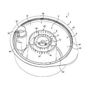
Figures 1 to 6 show a first embodiment of cartridge 1 according to the present
disclosure.
For clarity, cartridge 1 is illustrated containing no beverage ingredient so
that features of the
cartridge 1 may be more easily seen. However, prior to use, and during
assembly, the cartridge 1
would receive one or more beverage ingredients therein and then be sealed by
means of a lid 5
as will be described below, and as shown in Figure 6.
The cartridge 1 generally comprises a body 2, an inner member 3 and the lid 5.
The body
2, inner member 3 and lid 5 are assembled to form the cartridge 1.
The body 2 may generally comprise a cup-shaped member defining a beverage
ingredient chamber 6 within an interior thereof. The body 2 may have a curved
side wall 21, a
closed top 29 and an open bottom 30 defining an open mouth of the body 2 which
is surrounded
by a rim 46 and a flange 42 which extends radially outwards from the rim 46.
In addition, the body
2 may further define an optional annular void space 44 between an interior
wall 43 of the
container and the flange 42. In this case, a free edge of the interior wall 43
may define the rim 46.
The closed top 29 of the body 2 may comprise, as shown in Figure 6, a
centrally-located
cylindrical bore 40 that forms a depression in the outer surface of the body
2. A closed end of the
cylindrical bore 40 may comprise a cylindrical extension 24 of narrower
diameter compared to the
cylindrical bore 40, the function of which will be described further below.
The cartridge 1 further comprises an inlet point 13 and an outlet point 14 as
shown in
Figure 6. The inlet point 13 and the outlet point 14 define the location of an
inlet for aqueous
medium, such as water, to enter in use the cartridge 1 and the location of an
outlet for beverage
to leave the cartridge 1 during dispensation. Preferably the inlet and outlet
are initially sealed by
the lid 5 such that the inlet point 13 and outlet point 14 are simply
predetermined areas of the lid 5
to be pierced, cut or otherwise opened in use. Alternative forms of inlet and
outlet may be
provided, for example, in the form of valve elements or tear-off elements that
can be removed
manually or by the beverage preparation machine.
The body 2 of cartridge 1 may be generally circular or disc-shaped, with a
diameter of the
cartridge 1 being greater than its height. Typically the overall diameter of
the body 2 is 74.5 mm
6mm and the overall height is 29 mm 3 mm. Typically, the internal volume of
the cartridge 1
able to receive beverage ingredient(s) when assembled is a maximum of 55 ml
(although it is not
required that the internal volume is filled to capacity with beverage
ingredient(s)). The diameter of
CA 3011614 2018-07-17
- 12 -
the body 2 may be smaller at the closed top 29 compared to the diameter at the
bottom 30,
resulting from a flaring of the curved side wall 21 from the closed top 29 to
the bottom 30.
The body 2 may comprise an inlet chamber 32 adjacent to the curved side wall
21 aligned
with the inlet point 13. The inlet chamber 32 comprises a cylindrical wall
structure having a jetting
slot 33 at one side configured to jet, in use, the aqueous medium entering the
inlet chamber 32
from the inlet point 13 into the beverage ingredient chamber 6 such that the
aqueous medium
circulates energetically around the beverage ingredient chamber 6. The jetting
slot 33 may be an
elongated slot or slit. Preferably, the jetting slot 33 is orientated so that
the aqueous medium
enters the beverage ingredient chamber 6 at an angle greater than 45 ,
preferably at 90 , from a
radial direction of the beverage ingredient chamber 6.
The inner member 3 is located within the body 2. The inner member 3 is
connected to the
body 2 and comprises a mounting flange 50, a first filter 8, a second filter
9, a flow constriction
and a discharge spout 12. The inner member 3 may be located centrally within
the body 2 so that
a central axis of the inner member 3 is coincident with and aligned to a
central axis of the body 2.
The mounting flange 50 may be connected to an inner surface of the closed top
29 of the body 2,
for example by ultrasonic welding. On assembly, the inner member 3 spans
between the closed
top 29 of the body 2 and the lid 5, as shown in Figure 6. The lid 5 is sealed
to distal rims of the
inner member 3 as well as the body 2 as will be described below.
With the inner member 3 in position within the body 2, the beverage ingredient
chamber
6, which holds the beverage ingredient prior to dispensation, takes the form
of an annular
chamber extending between the curved side wall 21 of the body 2 and the inner
member 3.
The inner member 3 may be formed as a single integral moulding.
As shown in Figures 2 to 4, the first filter 8 may take the form of a tubular
member that
extends from the mounting flange 50 and defines a first cylindrical filter
wall 81 that forms an outer
surface of the inner member 3. The first cylindrical filter wall 81 is
provided at a distal end from the
mounting flange 50 with a plurality of first filtering apertures 82.
The second filter 9 is arranged within the first cylindrical filter wall 81
and takes the form
of a second cylindrical filter wall 91. The second cylindrical filter wall 91
extends from a transverse
connecting flange 17 that joins the second cylindrical filter wall 91 to the
first cylindrical filter wall
81. The second cylindrical filter wall 91 is provided at a distal end from the
mounting flange 50
with a plurality of second filtering apertures 92.
As shown in Figure 4, the transverse connecting flange 17 may be provided with
a
plurality of radial stiffening ribs 60 on its lower face which extend between
the first cylindrical filter
wall 81 and the second cylindrical filter wall 91. In addition, further
radially inwards, the transverse
connecting flange 17 may be provided with a plurality of radial stiffening
ribs 62 on its lower face
which extend between the second cylindrical filter wall 91 and a cylindrical
tube 16 which
surrounds the discharge spout 12. Further, radially inwards, the transverse
connecting flange 17
CA 3011614 2018-07-17
- 13 -
may be provided with a plurality of radial stiffening ribs 63 on its lower
face which extend between
the cylindrical tube 16 and a base of the discharge spout 12.
As shown in Figures 3 and 3a, the transverse connecting flange 17 may also be
provided
with a plurality of radial stiffening ribs 64 on its upper face which extend
between the first
cylindrical filter wall 81 and a cylindrical wall 66 which is aligned with the
second cylindrical filter
wall 91 but extends upwardly from the transverse connecting flange 17 in the
opposite direction
from the direction of the second cylindrical filter wall 91. In other words
the cylindrical wall 66 and
the second cylindrical filter wall 91 lie on opposite sides of the transverse
connecting flange 17.
In addition, further radially inwards, the transverse connecting flange 17 may
be provided
with a plurality of radial stiffening ribs 65 on its upper face which extend
between the cylindrical
wall 66 and cylindrical rim 20 which surrounds an upper end of the discharge
spout 12.
The first filtering apertures 82 and the second filtering apertures 92 are
preferably formed
as slots that are relatively thin in a circumferential direction of the first
cylindrical filter wall 81 and
second cylindrical filter wall 91 and relatively long in a longitudinal
direction thereof. The slots may
be configured to filter out beverage ingredient particles having a dimension
of at least 0.5mm,
preferably in the range 0.5-2mm. A critical dimension (being the smallest
dimension, for example
the width) of the slots of the first cylindrical filter wall 81 and second
cylindrical filter wall 91 may
be 0.4 to 0.6 mm, preferably 0.5mm, in order to capture the larger particles
but allow flow of the
beverage out of the beverage ingredient chamber 6 without an unwanted
substantial increase in
back-pressure. The slots may extend from a free edge (i.e. the rim) of each of
the first cylindrical
filter wall 81 and second cylindrical filter wall 91. The slots in the first
cylindrical filter wall 81 may
be 3.0 mm long. The slots in the second cylindrical filter wall 91 may be 1.8
mm long.
The first filter 8 and second filter 9 may each be formed from a rigid,
impermeable
material, such as a plastics material, such that none of the beverage, aqueous
medium or
beverage ingredient may pass through the first filter 8 and second filter 9
except through the first
filtering apertures 82 and second filtering apertures 92.
As shown in Figure 2, the second cylindrical filter wall 91 is arranged within
the first
cylindrical filter wall 81. The second filter 9 is in this way arranged
downstream of, and spaced
apart from, the first filter 8 even though the first filter 8 and second
filter 9 may both be formed as
integral parts of the inner member 3. The first cylindrical filter wall 81 and
second cylindrical filter
wall 91 may be arranged concentrically with one another and also be centred on
the central axis
of the body 2 when assembled.
The discharge spout 12 of the inner member 3 is arranged for channelling the
beverage
towards the outlet point 14 of the cartridge 1. As illustrated in Figure 6,
the outlet point 14 may be
provided at or near the central axis of the cartridge 1. The discharge spout
12 may be surrounded
by the cylindrical tube 16 which extends part-way along the length of the
inner member 3 from the
transverse connecting flange 17. The discharge spout 12 and cylindrical tube
16 may be
arranged concentrically within the second cylindrical filter wall 91. Thus,
preferably all of the first
CA 3011614 2018-07-17
- 14 -
cylindrical filter wall 81, second cylindrical filter wall 91, cylindrical
tube 16 and discharge spout 12
are arranged concentrically to one another and centred on the central axis of
the cartridge 1.
An annular space 18 is defined between an inner face of the second cylindrical
filter wall
91 and an outer face of the cylindrical tube 16. The cylindrical tube 16 is
not provided with any
openings and does not allow passage of fluid across its wall. Instead, fluid
communication
between the annular space 18 and the discharge spout 12 is provided by a
channel 19 as shown
in Figures 3 to 5. The channel 19 defines a passage, akin to a chimney,
extending parallel to the
central axis of the cartridge 1 from the vicinity of the second filtering
apertures 92 and through the
transverse connecting flange 17. The channel 19 is defined by two curved walls
19a and 19b that
extend, on the lower side of the transverse connecting flange 17, between the
second cylindrical
filter wall 91 and the cylindrical tube 16 and extend, on the upper side of
the transverse
connecting flange 17, between the cylindrical wall 66 and the cylindrical rim
20. The lower end of
the two curved walls 19a and 19b stops short of the rims of the second
cylindrical filter wall 91
and the cylindrical tube 16 so as to form an entry point 67 of the channel 19.
An exit point of the
channel 19 at the upper end of the channel 19 is in fluid communication with
the flow constriction
as will be described further below.
The cartridge 1 may be provided with means for entraining air into the
beverage, for
example in the form of an eductor. As used herein, the term eductor refers to
the use of a flow
constriction in the form of an aperture, or similar structure, to form a jet
of beverage, the aperture
being located in the beverage flow path upstream of an air inlet 27 and an
expansion chamber,
said aperture being arranged to produce a jet of beverage which jets into the
expansion chamber
to produce a low pressure zone in the vicinity of the air inlet 27 which
causes air to be drawn
through the air inlet 27 and to become entrained in the beverage stream as a
plurality of bubbles.
In the first embodiment of Figures 1 to 6, the flow constriction is arranged
downstream of
the second filter 9, that is downstream of the second cylindrical filter wall
91. As shown in Figures
3, 3a and 6, the cylindrical rim 20 surrounds an inlet to the discharge spout
12. An inwardly
directed shoulder 26 is provided immediately within the cylindrical rim 20. At
one point around the
circumference of the cylindrical rim 20 a slot 25 is provided, the slot 25
extending from an upper
edge of the cylindrical rim 20 to a point marginally below the level of the
inwardly directed
shoulder 26. As shown in Figure 6, when the cartridge 1 is assembled, the
cylindrical extension
24 of the body 2 is seated within the cylindrical rim 20 and rests against the
inwardly directed
shoulder 26. The cylindrical extension 24 substantially closes off the inlet
of the discharge spout
12 including closing off the upper end of the slot 25. Because the slot 25 in
the cylindrical rim 20
extends below the level of the inwardly directed shoulder 26, the aperture for
forming a jet of
beverage remains open to provide a fluid path through the cylindrical rim 20.
Thus on assembly,
the slot 25 together with the body 2 define the flow constriction in the form
of the resulting
aperture. The resulting aperture may be of dimension 0.65mm x 1.00mm with a
cross-sectional
area of 0.65MM2.
CA 3011614 2018-07-17
- 15 -
Preferably, the location of the slot 25 is aligned with the exit point of the
channel 19 as
shown in Figure 3a.
As shown in Figure 3a, the air inlet 27 is located immediately downstream of
the aperture
resulting from partial closure of the slot 25. The air inlet 27 may comprise a
round hole, but in the
illustrated embodiment comprises an elongated slot that extends through the
transverse
connecting flange 17 so as to provide gas communication between a point above
the transverse
connecting flange 17 within an upper part of the discharge spout 12 and a void
space below the
transverse connecting flange 17 between the cylindrical tube 16 and the
discharge spout 12.
Preferably, the air inlet 27 is circumferentially aligned with the slot 25.
The air inlet 27 is provided
within a tapered channel 70 formed in line with the slot 25. The tapered
channel 70 comprises a
floor and two side walls that converge towards a lip 72. The air inlet 27 may
be located towards a
root of the tapered channel 70 adjacent the cylindrical rim 20.
The upper end of the discharge spout 12 may also be provided with a plurality
of
upstanding projections 71 which extend upwards from the transverse connecting
flange 17 and
surround a mouth of the exit bore of the discharge spout 12.
The diameter of the first cylindrical filter wall 81 may be relatively large
compared to the
internal diameter of the beverage ingredient chamber 6. For example, the
diameter of the first
cylindrical filter wall 81 may be 29 mm and the maximum internal diameter of
the beverage
ingredient chamber 6 may be 57 mm. Therefore, each side of the resultant
annular beverage
ingredient chamber 6, as shown in Figure 6, has a width, w, of 14 mm and a
height, h, of 29 mm.
Thus a void space is provided that allows beverage ingredient(s) to be filled
into the cartridge 1
where the local bed thickness of the beverage ingredient(s) is approximately 2
times the local bed
width of the beverage ingredient(s).
The lid 5 may be formed from a composite material. The composite material may
comprise an aluminium layer. The composite material may comprise one or more
polymer layers,
for example a polypropylene layer and/or a polyethylene terephthalate (PET)
layer.
When sealed to the body 2, the lid 5 forms a seal with the flange 42 of the
body 2 and
also a rim of the inlet chamber 32. In addition, the lid 5 is sealed to the
distal end of the inner
member 3, namely the rims formed by the free edges of the first cylindrical
filter wall 81, the
second cylindrical filter wall 91 and the cylindrical tube 16.
The cartridge 1 may contain one or more beverage ingredients in the beverage
ingredient
chamber 6. The cartridge 1 of the present disclosure finds particular
application where the one or
move beverage ingredients are one or more soluble beverage ingredients. For
example, the one
or more beverage ingredients may comprise one or more powdered beverage
ingredients. The
one or more beverage ingredients may comprise insoluble- or reduced solubility-
particles, for
example, cocoa powder or powder mixes containing coarsely ground spices (e.g.
cinnamon). A
non-exhaustive list of example beverage ingredients includes chocolate powder,
milk powder,
CA 3011614 2018-07-17
- 16 -
creamers, soluble coffee, fruit and vegetable powders, flavourings, herbs and
partially/coarsely
ground spices including but not limited to cinnamon, ginger, cardamom, etc.
In use, the sealed cartridge 1 is inserted in, or otherwise coupled to, a
beverage
preparation machine in order to dispense a beverage (or beverage part) from
the cartridge 1.
During operation of the dispensation cycle an inlet is formed at the inlet
point 13 and an outlet is
formed at the outlet point 14, for example, by piercing of the lid 5 by
elements of the beverage
preparation machine. A beverage flow path can then be defined linking the
inlet point 13 to the
outlet point 14 along which an aqueous fluid, which will be exemplified in the
following as hot
water, can pass. The beverage flow path is defined by spatial inter-
relationships between the
body 2, the inner member 3 and the lid 5.
The beverage flow path passes, in order, from the inlet point .13, through the
inlet
chamber 32, out of the jetting slot 33, around the annular beverage ingredient
chamber 6, through
the first filtering apertures 82 of the first cylindrical filter wall 81,
through the second filtering
apertures 92 of the second cylindrical filter wall 91, into the annular space
18, into and up the
.. channel 19, through the aperture of the eductor, over the air inlet 27 of
the eductor, into the
discharge spout 12 and finally arrives at the outlet point 14. From the outlet
at the outlet point 14
the beverage may be discharged into a suitable receptacle.
The orientation of the jetting slot 33 causes the hot water entering the
annular beverage
ingredient chamber 6 to swirl and circulate around the inner member 3,
potentially a large number
of times. In so doing the hot water is better able to dissolve the soluble
beverage ingredients. In
particular the energetic nature of the jet of hot water from the jetting slot
33 and the circulation of
the hot water around the full circumference of the annular beverage ingredient
chamber 6 helps to
break up any agglomerations of soluble beverage ingredient within the
cartridge 1. Further, whilst
not wishing to be bound by theory, the configuration wherein the local bed
thickness of the
beverage ingredient is 1.5 to 2.2 times the local bed width of the beverage
ingredient, is believed
to assist with the break-up of agglomerations of soluble beverage ingredients
by firstly, confining
the circulating water to a relatively narrow annular volume which results in
maintenance of higher
water velocities within the beverage ingredient chamber 6 and, secondly, by
providing a larger
circumferential surface area of the beverage ingredient that can be directly
exposed to the water.
Whilst not wishing to be bound by theory, the dispersion and dissolution of
the soluble
beverage ingredients is understood to be driven by the shear stress applied to
break-up the
wetted powder mass of the soluble beverage ingredients as it is contacted by
the water. By use
of the first cylindrical filter wall 81, which may be relatively large
compared to the internal diameter
of the beverage ingredient chamber 6, the shear rate of the water may be
increased and thereby
the shear stress applied to the wetted powder mass of the beverage ingredient
mix can be
increased leading to better dissolution of the soluble beverage ingredients.
For a 3-2 mm2 inlet
area and operating at pressures from 0.6 to 1.2 bar the pump in a test system
was found to give
a flow rate of 5.5 to 3.6 ml/s into the inlet point 13. The velocity of the
fluid, V, thru the inlet point
CA 3011614 2018-07-17
- 17 -
13 was in the range 0.9 to 1.8 m/s. Where the annular width of the beverage
ingredient chamber
is 9.5 mm, dividing the inlet velocity by this gap gives estimates of applied
shear rates in the
chamber of between 95 to 190 1/s.
The beverage thus formed from the hot water and the dissolved beverage
ingredients is
then able to pass out of the beverage ingredient chamber 6 through the first
filtering apertures 82
of the first cylindrical filter wall 81 and then the spaced apart second
filtering apertures 92 of the
second cylindrical filter wall 91. The first and second filtering apertures
82, 92 act to filter out from
the beverage any insoluble particles that may have been present in the
beverage ingredients and
also particles that have a reduced solubility such that for whatever reason
the particles are not
dissolved during the dispensation cycle.
Thus the first filter 8 defines an exit from the beverage ingredient chamber 6
and the
second filter 9 forms a secondary filter which improves the filtering
performance of the cartridge 1.
The size of the second filtering apertures 92 may be smaller than the size of
the first filtering
apertures 82 so that the first filter 8 acts as a 'coarse' filter and the
second filter 9 acts as a 'fine'
filter.
By providing the first and second filtering apertures 82, 92 to be arranged
around a major
portion of the circumference, respectively, of the first and second
cylindrical filtering walls 81, 91
dispensation performance of the cartridge 1 is maintained even as the first
and second cylindrical
filter walls 81, 91 retain and hold back particles on their upstream sides.
This may be for two
reasons. Firstly, the relatively large surface area of the first filter 8 and
the second filter 9 (since
they extend around a major portion of the circumference) means that even if
some filtering
apertures 82, 92 become blocked enough other filtering apertures 82, 92 are
present to allow
adequate through-flow of beverage without creating too high a level of back-
pressure within the
cartridge 1. Secondly, the cylindrical shape of, particularly, the first
filter 8 means that there is a
tendency for filtered particles held back by the first filtering apertures 82
to be 'washed off' the first
filter 8 by the circulating hot water/beverage mix within the annular beverage
ingredient chamber
6 so that the filtered particles tend to get carried back into circulating
fluid flow rather than
remaining trapped against the first filtering apertures 82.
A particular advantage is that the first filter 8 and the second filter 9
prevent beverage
ingredient particles larger than a desired predetermined size from reaching
the flow constriction,
preventing the flow constriction from becoming partially or totally blocked by
such particles.
The back pressure of beverage collecting in the beverage ingredient chamber 6
forces
the beverage under pressure through the first filter 8, the second filter 9,
the annular space 18
and up the channel 19. The beverage then passes through the eductor. In so
doing, the jet of
beverage passes over the air inlet 27. As a result air is entrained into the
beverage stream in the
form of a multitude of small air bubbles as the air is drawn up through the
air inlet 27. The jet of
beverage issuing from the aperture turbulently flows within the upper part of
the discharge spout
12 wherein collisions with the upstanding projections 71 help to modify the
bubble size within the
CA 3011614 2018-07-17
- 18 -
beverage. The beverage is then funnelled downwards along the exit bore of the
discharge spout
12 to the outlet where the beverage is discharged into a receptacle such as a
cup where the air
bubbles form the desired frothy appearance.
Various modifications may be made to the cartridge 1 of the present disclosure
as
described above without departing from the scope of the present disclosure. In
the following
passages of the description a number of modifications and alternatives will be
described that may
be made singularly or in any combination unless the context explicitly states
otherwise. In the
following only the changes will be described in detail. In other respects the
cartridges 1 are as
described above. In the following description, like numbers are used for like
features and
components.
Figures 7 to 8 show an alternative form of inner member 103 that may be used
with the
body 2 as described above to form a further embodiment of cartridge 101. Inner
member 103 is
similar to the inner member 3 described above except in that it comprises a
second flow
constriction and a second air inlet 127 is provided in the transverse
connecting flange 17. The
second flow constriction and second air inlet 127 have the same form as the
flow constriction and
the air inlet 27. In each case the size of the resulting aperture of the
eductor is half the size
compared to the first embodiment ¨ each aperture having a cross-sectional area
of 0.65mm x
0.5mm = 0.33mm2. Thus the combined open area of the two eductor apertures is
the same as the
open area of the single eductor aperture of the first embodiment.
The second air inlet 127 is circumferentially aligned with the second flow
constriction. In
addition, the second air inlet 127 and second flow constriction are spaced
from the air inlet 27 and
the first flow constriction around the circumference of the annular flange 17.
Preferably they may
be located diametrically opposite the air inlet 27 and flow constriction 10 as
shown in Figure 8.
Another difference is that the second cylindrical filter wall 91 extends
directly from the
mounting flange 50 rather than from the transverse connecting flange 17. Thus,
the transverse
connecting flange 17 in this embodiment only extends radially inwardly from
the second cylindrical
filter wall 91. As a consequence the radial stiffening ribs 160 between the
first cylindrical filter wall
81 and the second cylindrical filter wall 91 are taller than in the first
embodiment described above.
As well as the channel 19, a second channel 119 is provided to provide fluid
communication between the annular space 18 and the discharge spout 12. The
second flow
constriction is arranged downstream of the second channel 119 such that two
flow paths from the
annular space 18 to the discharge spout 12 are defined, the first flow path
passing through the
channel 19 which now forms a first channel and first flow constriction and the
second flow path
passing through the second channel 119 and the second flow constriction.
Since the second flow constriction is spaced from the first flow constriction
around the
circumference of the annular flange 17 in use the jets of beverage emerging
from the first flow
CA 3011614 2018-07-17
- 19 -
constriction and second flow constriction collide in the upper part of the
discharge spout 12,
resulting in improved mixing and frothing of the beverage. In the preferred
arrangement, where
the two eductors are diametrically opposite one another, the jets of beverage
impact one another
substantially head-on. The inclusion of the second flow constriction has been
found to result in
reduced back pressure within the cartridge 101 in use.
In use, the back pressure of beverage collecting in the beverage ingredient
chamber 6
forces the beverage under pressure through the first filter 8 and the second
filter 9 as described
above. The flow of beverage then separates into two flows the first flow
passing through the first
channel 19 and first flow constriction and the second flow path passing
through the second
channel 119 and the second flow constriction, emerging from each flow
constriction as a jet into
the upper end of the discharge spout 12. A first jet of beverage emerges from
the first flow
constriction and passes over air inlet 27. A second jet of beverage emerges
from the second flow
constriction and passes over the second air inlet 127. As a result air is
entrained into both
beverage streams in the form of a multitude of small air bubbles as the air is
drawn up through the
.. air inlets 27, 127. The two jets collide in the discharge spout 12 before
being funnelled
downwards to the outlet.
Figures 9 to 11 show another alternative form of inner member 203 that may be
used with
the body 2 described above or a modified body 202 described below to form a
further
embodiment of cartridge 201.
As before, the cartridge 201 comprises an inlet chamber 32. However, the inlet
chamber
32 is not provided with a jetting slot 33 communicating directly with the
beverage ingredient
chamber 6. Rather, the inlet chamber 32 is provided with opposed slots 133
which communicate
with the annular void space 44. In addition, the interior wall 43 is provided
with a pair of inlets 213
arranged at opposite sides of the beverage ingredient chamber 6 as shown in
Figure 9. The pair
of inlets 213 may be diametrically opposite one another and may be in the form
of small slots in
the interior wall 43.
The cartridge 201 further comprises the alternative form of inner member 203.
The inner
member 203 comprises a filter 208, a first flow constriction, a second flow
constriction, and a
discharge spout 12. The filter 208 defines an exit from the beverage
ingredient chamber 6. The
filter 208 performs the same function as the first filter 8 described above.
In this embodiment there
is no second filter. The first flow constriction and second flow constriction
are arranged
downstream of the filter 208.
The filter 208 comprises a cylindrical filter wall 281 having a plurality of
filtering apertures
282 located therein. The cylindrical filter wall 281 is in the form of a
tubular member comprising
the filtering apertures 282. The filtering apertures 282 are preferably formed
as slots that are
relatively thin in a circumferential direction of the cylindrical filter wall
281 and relatively long in a
longitudinal direction thereof. The slots may be configured to filter out
beverage ingredient
CA 3011614 2018-07-17
- 20 -
particles having a dimension of at least 0.5mm, preferably in the range 0.5-
2mm. A critical
dimension (being the smallest dimension, for example the width) of the slots
of the cylindrical filter
wall 281 may be 0.4 to 0.6 mm, preferably 0.5mm, in order to capture the
larger particles but
allow flow of the beverage out of the beverage ingredient chamber 6 without an
unwanted
substantial increase in back-pressure. The slots may extend from a free edge
(i.e. the rim) of the
cylindrical filter wall 281. The slots in the cylindrical filter wall 281 may
be 3.0 mm long.
The discharge spout 12 and cylindrical tube 16 of the inner member 203 are
arranged
within the cylindrical filter wall 281 and connected thereto by the transverse
connecting flange 17
as before.
An annular space 218 is defined between an inner face of the cylindrical
filter wall 281
and an outer face of the cylindrical tube 16. Fluid communication between the
annular space 218
and the discharge spout 12 is provided by the channel 19 which now forms a
first channel and a
second channel 119 as in the embodiment described above. The arrangement of
the first flow
constriction, second flow constriction and the discharge spout 12 are as
described for inner
member 103.
The diameter of the cylindrical filter wall 281 may be smaller than that of
the first
cylindrical filter wall 81 of the embodiments described above. For example,
the diameter of the
cylindrical filter wall 281 may be 18.5 mm. As before, the maximum internal
diameter of the
beverage ingredient chamber 6 may be 57 mm. Therefore, each side of the
resultant annular
beverage ingredient chamber 6 has a width, w, of 19 mm and a height, h, of 29
mm. Thus a void
space is provided that allows beverage ingredient to be filled into the
cartridge 1 where the local
bed thickness of the beverage ingredient is approximately 1.5 times the local
bed width of the
beverage ingredient.
Use of the cartridge 201 is the same as described above with reference to
cartridge 101
including inner member 103 except in the differences described below.
On injection of the hot water into the inlet chamber 32, the water passes
through the
opposed slots 233 into the annular void space 44 until it reaches the pair of
inlets 213. The water
is then diverted to be jetted into the beverage ingredient chamber 6 in a
radial direction towards
the inner member 203. The water impacts on the inner member 203 and then
rebounds and sets
up a circulatory pattern within the annular beverage ingredient chamber 6. As
before, passage of
the hot water within the annular beverage ingredient chamber 6 acts to
dissolve the soluble
beverage ingredients.
The back pressure of beverage collecting in the annular beverage ingredient
chamber 6
forces the beverage under pressure through the filter 208. The beverage passes
directly into the
annular space 218. The flow of beverage then separates into two flows, the
first flow passing
through the first channel 19 and first flow constriction and the second flow
path passing through
the second channel 119 and the second flow constriction as in inner member
103. Thereafter,
dispensation is as described previously.
CA 3011614 2018-07-17
-21 -
As noted, the described modifications and alternatives above may be made
singularly or
in any combination, not only in those combinations explicitly mentioned above
in the described
embodiments. For example, as utilised in some of the worked examples below,
embodiments of
.. the cartridge according to the present disclosure may combine the body 2 of
Figure 1 (having the
jetting slot 33) with an inner member (not illustrated) having a single
cylindrical filter wall 281
having filtering apertures 282 and a single eductor. Or in another example,
the cartridge may
combine the body 202 of Figure 9 (having the opposed slots 133) with an inner
member (not
illustrated) having a single cylindrical filter wall 281 having filtering
apertures 282 and a single
eductor.
Examples
In the following examples cartridges were prepared and then dispensed in a
beverage machine
.. using hot water at -85 C.
In each test the same composition of beverage ingredients was used - which was
a conventional
soluble chocolate beverage ingredient mix, comprising:
sugar (-45-50 %)
cocoa powder (-5-10%)
whole milk powder (-5-10%)
Skim milk powder (-15-25%)
whey powder (0-15%)
creamer (0-10%)
with the balance other minor ingredients such as flavours (<1%).
In all cases the soluble powder chocolate beverage ingredient mix was loaded
into the cartridge
at fill weights ranging from 25-33 g. The cartridge was then sealed with the
lid 5. The cartridge
was dispensed in a Tassimo T-20/Amia beverage preparation machine running at
240 V. During
dispensation the peak pressures during the 'brew' stage and the 'purge' stage
were measured
and recorded. The 'brew' stage is the period of the dispensation cycle where
the bulk of the hot
water is injected into the cartridge to mix with the beverage ingredients and
be directed into the
receptacle. The 'purge' stage follows the 'brew' stage and involves the
injection of steam through
the cartridge (although some residual water may also be present) in order to
drive out as far as
possible liquid from the cartridge into the receptacle. At the end of beverage
dispensation, the
drink weight delivered into the receptacle and the weight of the wet cartridge
were recorded.
Finally the wet cartridges were put in an oven at -103-105 C for three hours
or until all the water
had evaporated. The dry residue in grams was measured by weighing the dry
cartridges and then
CA 3011614 2018-07-17
- 22 -
the % solids in cup was calculated and expressed as % yield in cup. All tests
were repeated 100
times and the results for each cartridge type were averaged.
A summary of the results is shown in Table 1 below, wherein:
For Example 1 ¨ a comparative example of a cartridge as shown in Figure 12 was
used having a
body 202 of the same type as shown in Figure 9, an inner member 303 having a
cylindrical wall
381 of diameter 18.5mm and provided with large apertures 382 (not filtering
apertures) and
having a single eductor. The fill weight of beverage ingredient is 33g.
For Example 2 ¨ a cartridge as shown in Figure 13 was used having a body 202
of the same type
as shown in Figure 9, an inner member 403 similar to the inner member 203 as
shown in Figure
10 in that it has a single cylindrical filter wall 281 of diameter 18.5mm but
only a single eductor.
The fill weight is 33g.
For Example 3 ¨ a cartridge was used comprising a body 2 as shown in Figure 1,
an inner
member having a single cylindrical filter wall of diameter 29mm and having
filtering apertures and
a single eductor. The fill weight is 25g.
For Example 4 ¨ a cartridge was used comprising a body 2 as shown in Figure 1
and an inner
member 103 as shown in Figures 7 and 8 having first and second cylindrical
filter walls 81, 91
having filtering apertures therein with the first cylindrical filter wall 81
having a diameter of 29mnn.
The fill weight is 25g.
For Example 5 ¨ the cartridge used being the same as Example 2 but with a fill
weight of 26g.
In each the example the cartridge is sealed with a lid.
CA 3011614 2018-07-17
_
o
- 23-
0
i-
I-,
61
I-' Table 1
0.
Average Average
Average Average Average Average
IQ Powder Fill
0 No. of Drink Peak Purge Peak
Brew Wet Dry
Yield1-,
co inlets
Disc Description Weights (g) Weight
Pressure Pressure Residue Residue (%)
I
0 (g) (bar) (bar)
(g) (%)
...1
I Example 1 2 33 183 2.1 1.6
10.37 18 82
I-,
--1
Example 2 2 33 180 1.6 1.0
11.3 23 77
Example 3 1 25 175 1.7 1.2
8.7 15 85
_
Example 4 1 25 180 0.9 0.6
4.5 9 91
Example 5
2 26 179 1.5 0.9
5.4 12 88
=
- 24 -
As can be seen from the results, the cartridges of Example 1 which do not have
a first
filter 8 or second filter 9 according to the present disclosure and only
possess a single flow
restriction in the form of a single eductor suffer from relatively high peak
pressures ¨ during the
brew stage of 1.6 bar and during the purge stage of 2.1 bar. Whilst not
wishing to be bound by
theory it is believed that the high peak pressures are caused by partial or
full blockage (for at least
some of the dispensation cycle) of the single flow restriction at the
narrowest point of the slot of
the eductor by particles of the beverage ingredient(s) that are either
relatively insoluble or have
not dissolved sufficiently before reaching the flow restriction. The yield
from the cartridges is also
relatively low at 82%.
The cartridges of Example 2 which possess only a single filter and a single
flow restriction
in the form of a single eductor benefit from slightly reduced peak pressures
compared to Example
1 ¨ during the brew stage of 1.0 bar and during the purge stage of 1.6 bar.
However, the yield
from the capsules is low at 77%.
By contrast the cartridges of Examples 3 to 5, benefit from significantly
reduced peak
pressures in combination with improved yields. Most preferably, the cartridges
of Example 4 have
low peak pressures - during the brew stage of 0.6 bar and during the purge
stage of 0.9 bar in
combination with the yield from the capsules being increased to 91%.
Whilst not wishing to be bound by theory it is believed that the improvements,
in particular
for the cartridges of Examples 3 to 5, comes from a combination of factors.
The provision of at
least one filter in the form of a filter wall with filtering apertures is
believed to help to prevent
partial or full blockage of the flow restriction(s) at the narrowest point of
the slot of the eductor(s)
by particles of the beverage ingredient(s) that are either relatively
insoluble or have not dissolved
sufficiently, since those particles are held back by the filtering apertures
upstream of the flow
restriction. In addition, configuring the filter as a cylindrical filter with
a large number of individual
filtering apertures in the form of slots means that even if some are blocked,
others remain to allow
the beverage to flow onwards towards the outlet point. Further the swirling,
circulating flow within
the annular beverage ingredient chamber 6 may have a tendency to Wash' away
the particles
from the surface of the filter wall leading to re-opening of blocked filtering
apertures. This
beneficial effect is enhanced where the inner member has a relatively large
diameter compared to
the body so that the local bed thickness of the beverage ingredient is 1.5 to
2.2 times the local
bed width of the beverage ingredient.
Various further modifications will now be described which may be made to any
of the
cartridges of the present disclosure as described above (or other cartridges)
without departing
from the scope of the present disclosure. In the following passages of the
description a number of
modifications and alternatives will be described that may be made singularly
or in any
combination unless the context explicitly states otherwise. In the following
only the changes will
1,510,
CA 30116142019-10-29
- 25 -
be described in detail. In other respects the cartridges may be as described
above. In the
following description, like numbers are used for like features and components.
As shown in Figures 14 and 14b a conduit upstream of the or each flow
constriction may
be configured to prevent deposition of undissolved or partially dissolved
beverage ingredient. As
can be seen in the version of the cartridge shown in Figure 14a, the shaping
and sizing of the
centrally-located boss 40 with its cylindrical extension 24 can result in
there being a 'dead space'
150 at an upper end of the channel 19 immediately upstream of each flow
constriction 10. In the
modified cartridge shown in Figure 14b the portion of the channel 19
immediately upstream of the
flow constriction 10 has been smoothed by extending the centrally-located boss
40 so that it
terminates flush with the upper edge of the slot 25 of the flow restriction
10. This results in there
not being any dead spaces, sharp corners or sudden changes in concavity
upstream of the flow
restriction which might encourage particle deposition.
As shown in Figures 15 to 18, the beverage ingredient chamber 6 may comprise
one or
more partition elements 151 which act to demarcate two or more zones 6a to 6d
within the
beverage ingredient chamber 6, each of which contain the one or more beverage
ingredients.
Preferably, the one or more partition elements 151 extend from the first
filter 8 towards the body
2 of the cartridge 1. The one or more partitions 151 may be planar as shown in
Figure 16 and
may be orientated radially within the body 2. In the example shown in Figures
15 and 16 there are
four partitions 151 provided equi-spaced around the circumference.
Figure 17 shows an alternative wherein the one or more partitions 152 are
curved. This
may aid funnelling of the beverage towards the first filter 8.
The one or more partitions 151, 152 may extend from the centrally-located
first filter 8
towards the surrounding wall of the body 2. Alternatively, as shown in Figure
18, partitions 153
may be provided which extend into contact with the surrounding wall of the
body so as to fully
separate zones 6a to 6d, one from the other, within the beverage ingredient
chamber 6. Each,
separate, zone 6a to 6d will comprise at least one inlet 33 permitting entry
of the aqueous
medium into the zone and at least a portion of the first filter 8 permitting
exit of beverage from the
zone.
Advantageously, separating the beverage ingredient chamber 6 into two or more
zones
6a to 6d can produce better dissolution of the one or more beverage
ingredients by focussing the
mixing of the aqueous medium and the beverage ingredients in key areas and
providing
alternative flow patterns.
As shown in Figures 19 to 21, a flow path from the filter(s) 8,9 to the flow
constriction(s)
10 may be configured to be spiral in shape. For example, spiral ramp elements
154 may be
located within the annular space 18 between the terminal filter (the second
filter 9 where present,
14111.04.
CA 30116142019-10-29
- 26 -
or the first filter 8 where only one filter is provided) and the cylindrical
tube 16, wherein the
beverage is forced to flow through the annular space 18 on the way to the flow
constriction(s) 10.
The spiral ramp elements 154 cause the beverage to spiral around the
cylindrical tube 16 creating
additional mixing vortices and swirl within the beverage. Advantageously, this
flow pattern can
help to break up small, partially wetted clumps of beverage ingredient which
may have managed
to pass the filter(s). Additional obstructions 155, for example, ribs,
corners, etc. can be provided
on the spiral ramp elements 154 to aid break-up of clumps. In the illustrated
example, four spiral
ramp elements 154 are provided equi-spaced around the circumference with each
spiral ramp
element 154 turning through approximately 90 degrees.
As shown in Figures 22 to 24, the beverage ingredient chamber 6 may contain a
plurality
of bristles 156. The bristles 156 advantageously can act to disrupt the flow
path with the beverage
ingredient chamber 6 to promote turbulence and better mixing of the one or
more beverage
ingredients. The bristles 156 may be arranged around, and spaced from, the
first filter 8. The
bristles 156 may comprise elongate plastic pins. The bristles may extend the
full height of the
beverage ingredient chamber 6. The bristles 156 may be formed unitarily as
part of the inner
member 3 also comprising the first filter 8 received within the body 2. In the
example shown, the
bristles 156 extend downwards from the mounting flange 50. The bristles 156
are arranged in
three concentric rings about the first filter 8. The spacing between
neighbouring bristles 156 is
.. such that the bristles 156 do not carry out a filtering function but rather
act to break up
agglomerations of powdered beverage ingredient.
As shown in Figure 25 the body 2 of the annular beverage ingredient chamber 6
may
comprise Multiple inlet points 33, each of which may be angled so that the
flow of aqueous
medium entering is stopped from entering radially but is rather angled at
greater than 45 and
preferably at 90 . As shown in Figure 25 the angling may be achieved by
providing an L-shaped
cover 160 to each inlet slot 33 so that the flow is turned through 90 before
entering the annular
beverage ingredient chamber. As shown the body comprises four inlet points 33
spaced at 90
from each other. Other numbers of inlet points can be provided.
As shown in Figure 26, the body 2 defining the beverage ingredient chamber 6
may have
one or more lobes 162 as part of an outer side wall of the beverage ingredient
chamber 6. The
one or more lobes 162 may be smoothly, convexly curved (when viewed from a
centre-point of
the cartridge) with a smooth inwardly-directed face 163. A lobe 162 may be
provided between
pairs of inlet apertures 33 to the beverage ingredient chamber 6.
Advantageously, the one or
more lobes 162 can improve dissolution of the one or more beverage ingredients
by first,
confining the incoming aqueous medium to a smaller cross-sectional flow area
leading to
improved shear forces and higher flow velocities which improve dissolution.
Secondly, the one or
#18473611
CA 3011614 2018-07-17
- 27 -
more lobes 162, when positioned between pairs of inlet apertures 33, tend to
decrease the
amount of 'dead space' in the beverage ingredient chamber 6. By 'dead space'
is meant that part
or parts of the volume of the beverage ingredient chamber 6 where circulating
flow of the aqueous
medium and/or beverage tends not to reach. For example, with an annular
beverage ingredient
chamber 6 having four equi-spaced radially-directed inlet apertures 33 at,
say, 00, 90 , 180 and
270 , it has been found that the locations by the side wall at 45 , 135 , 225
and 315 tend to be
'dead spaces' which tend not to be reached by circulating flow.
As shown in Figure 27 the beverage ingredient chamber 6 may comprise two or
more
separate chambers 164, 165 each of which hold a different beverage ingredient.
For example, a
first chamber 165 may hold sugar or a sugar-containing ingredient and a second
chamber 164
may hold a chocolate-containing ingredient. Each, separate, chamber will
comprise at least one
inlet 33a, 33b permitting entry of the aqueous medium into the chamber and at
least a portion of
the first filter 8 permitting exit of beverage from the chamber.
Advantageously, such an
arrangement can be used to tailor the size and number of inlet apertures and
the size and number
of filtering apertures to each ingredient.
As shown in Figure 28, the beverage ingredient chamber 6 may comprise a
dedicated
flow-conditioning chamber 168 which receives incoming aqueous medium in a
first condition and
discharges the aqueous medium into a remainder of the beverage ingredient
chamber in a
second condition. The first and second conditions may include one or more of:
first and second
flow velocities, first and second flow directions, and first and second flow
compositions. For
example, the flow-conditioning chamber 168 may comprise an angled wall 167 to
condition an
incoming aqueous medium that has a first condition of a relatively low flow
velocity, a radial flow
direction169 and a composition of pure water into a second condition of a flow
having a relatively
high flow velocity, a tangential flow direction 166 and a composition of water
mixed with one or
more beverage ingredients.
As shown in Figure 29, the beverage ingredient chamber 6 may comprise a plate
member
175 which initially rests on a bed of the one or more beverage ingredients.
The use of the plate
member 175 finds particular application where the inlet(s) 33 to the beverage
ingredient chamber
are located at or towards a bottom of the beverage ingredient chamber. In use,
as the one or
more beverage ingredients is incrementally dissolved away beneath the plate
member 175 the
weight of the plate member 175 (which may be freely movable within the
beverage ingredient
chamber 6) forces undissolved beverage ingredient higher up in the beverage
ingredient chamber
downwards into the path of the incoming aqueous medium. The plate member 175
may comprise
apertures 176 to allow for circulation of aqueous medium and/or beverage above
and below the
plate member in use as shown by arrows 177.
N1847368
CA 3011614 2018-07-17
- 28 -
As shown in Figure 30, the beverage ingredient chamber 6 may contain a
rotatable mixer
blade assembly 178. The rotatable mixer blade assembly 178 may comprise one or
more vanes
or blades 179 which act to break up agglomerations of powdered beverage
ingredient as the
rotatable mixer blade assembly 178 rotates within the beverage ingredient
chamber 6. Rotation of
the rotatable mixer blade assembly 178 is caused by the movement of the
aqueous medium and
in this case the rotation can be enhanced by jetting the aqueous medium into
the beverage
ingredient chamber 6 with an tangential directional component so as to
generate a whirling flow
within the beverage ingredient chamber 6.
As shown in Figures 31 and 32, the beverage ingredient chamber 6 may comprise
one or
more baffles orientated to induce vertical vortices within the beverage
ingredient chamber. In the
example of Figure 31 a curved baffle 190 is provided as part of the inner
member 3 and received
incoming aqueous medium that is jetted into the beverage ingredient chamber at
the bottom of
the chamber. The curved baffle 190 directs the flow upwards so that a vertical
vortex of flow is
created as shown by arrow 191. In the example of Figure 32 a baffle 193 is
provided at the base
of the beverage ingredient chamber 6 neat the inlet point 33 which causes the
incoming fluid to be
directed upwards initially to create a vertical vortex as shown by arrow 194.
The disclosure has been described above by way of example as having a body 2,
202
and inner member 3, 103, 203 formed as separate components which are conjoined
during
assembly of the cartridge. Alternatively the body 2, 202 and inner member 3,
103, 203 may be
formed as a single component.
The disclosure has been described above by way of example embodied in a
cartridge
formed from, amongst other parts, an outer member 2 and an inner member 3. In
particular, the
flow constriction has been described as delimited by portions of the body 2,
202 and inner
member 3, 103, 203. However, it is to be understood that the disclosure is
also applicable to
apertures formed in a single component rather than from the junction of two
components.
The one or more beverage ingredients may be a powder, a concentrated liquid or
a gel.
The cartridge described is suitable for any product which forms coagulates or
agglomerates or
which comprises particles susceptible to remaining undiluted by the aqueous
medium. For
example, beverage ingredients may be concentrated chocolate, flavour enhancing
syrups, vitamin
supplements or chocolate powder mix, containing insoluble particles of cocoa,
which are typically
0.5 to 2mm in size.
The cartridge 1, 101, 201 may be rigid, semi-rigid or flexible. The body 2,
may be formed
as a single integral piece from high density polyethylene, polypropylene,
polystyrene, polyester, or
a laminate of two or more of these materials. The body 2, 202 may be opaque,
transparent or
#1847368
CA 3011614 2018-07-17
- 29 -
translucent. The body 2, 202 and/or inner member 3, 103, 203 may be formed
from a
biodegradable polymer.
The body 2, 202 described above is generally circular or disc-shaped.
Alternatively, the
body 2, 202 may be of another form suitable for insertion into an on-demand
beverage machine,
for example the body 2, 202 may be frustroconical or cup-shaped.
The cartridge 1, 101, 201 may be closed by a rigid or semi-rigid lid instead
of a flexible
laminate.
#1847368
CA 3011614 2018-07-17