Language selection

Search

Patent 3012013 Summary

Third-party information liability

Some of the information on this Web page has been provided by external sources. The Government of Canada is not responsible for the accuracy, reliability or currency of the information supplied by external sources. Users wishing to rely upon this information should consult directly with the source of the information. Content provided by external sources is not subject to official languages, privacy and accessibility requirements.

Claims and Abstract availability

Any discrepancies in the text and image of the Claims and Abstract are due to differing posting times. Text of the Claims and Abstract are posted:

  • At the time the application is open to public inspection;
  • At the time of issue of the patent (grant).
(12) Patent: (11) CA 3012013
(54) English Title: BIDIRECTIONAL ECCENTRIC STABILIZER
(54) French Title: STABILISATEUR EXCENTRIQUE BIDIRECTIONNEL
Status: Granted
Bibliographic Data
(51) International Patent Classification (IPC):
  • E21B 17/10 (2006.01)
(72) Inventors :
  • SMITH, LEE MORGAN (Albania)
  • EASTUP-SMITH, BETTY A. (United States of America)
(73) Owners :
  • FRANK'S INTERNATIONAL LLC. (United States of America)
(71) Applicants :
  • SMITH, LEE MORGAN (United States of America)
  • EASTUP-SMITH, BETTY A. (United States of America)
(74) Agent: ROBIC AGENCE PI S.E.C./ROBIC IP AGENCY LP
(74) Associate agent:
(45) Issued: 2020-04-14
(22) Filed Date: 2018-07-19
(41) Open to Public Inspection: 2019-10-21
Examination requested: 2019-07-02
Availability of licence: N/A
(25) Language of filing: English

Patent Cooperation Treaty (PCT): No

(30) Application Priority Data:
Application No. Country/Territory Date
15/970,614 United States of America 2018-05-03

Abstracts

English Abstract

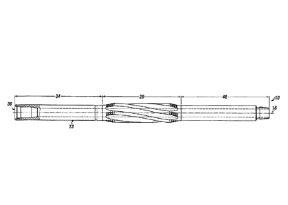
A drilling rig has a bidirectional eccentric stabilizer for use in a wellbore. The bidirectional eccentric stabilizer is coupled between a drill string and a bottom hole assembly. The bidirectional eccentric stabilizer has a shaft connected between a first shaft end and a second shaft end, an annulus formed longitudinally through the shaft and a cutting portion formed on an outer surface of the shaft. The cutting portion has a first cutting portion, a second cutting portion, a plurality of helical blades, a plurality of flutes, a plurality of cutting nodes, and a plurality of impact arrestors. The bidirectional eccentric stabilizer has a center of eccentric rotation which is offset from the longitudinal axis of the shaft, enabling the bidirectional eccentric stabilizer to form a larger wellbore than a drill bit on the bottom hole assembly and a larger diameter wellbore than originally drilled by the drill bit.


French Abstract

Un appareil de forage a un stabilisateur excentrique bidirectionnel destiné à être utilisé dans un puits de forage. Le stabilisateur excentrique bidirectionnel est couplé entre un train de tiges et un ensemble de fond de trou. Le stabilisateur excentrique bidirectionnel a un arbre connecté entre un premier et un second bout darbre, un espace annulaire formé longitudinalement à travers larbre et une partie de coupe formée sur une surface externe de larbre. La partie de coupe a une première et une seconde partie de coupe, une pluralité de lames hélicoïdales, une pluralité de cannelures, une pluralité de nuds de coupe et une pluralité de dispositifs darrêts dimpact. Le stabilisateur excentrique bidirectionnel a un centre de rotation excentrique qui est décalé par rapport à laxe longitudinal de larbre, permettant au stabilisateur excentrique bidirectionnel de former un plus grand puits de forage quun trépan sur lensemble de fond de trou et un puits de forage ayant un diamètre plus grand que celui initialement percé par le trépan.

Claims

Note: Claims are shown in the official language in which they were submitted.


CLAIMS

What is claimed is:

1. A drilling rig having a bidirectional eccentric stabilizer for use in a
wellbore, wherein the
bidirectional eccentric stabilizer is coupled between a downhole drill string
and a bottom
hole assembly, comprising:
a. the drilling rig comprising:
i. a tower having a crown with sheaves;
a drawworks connected to a drawworks motor and connected to a power
supply;
a cable extending from the drawworks through the sheaves over the crown;
iv. a lifting block connected to the cable;
v. a hydraulic pump connected to a tank for flowing fluid into the wellbore
as
a drill pipe is turned into the wellbore;
vi. a rotating means for turning the drill pipe into the wellbore, the
rotating
means comprising at least one of: a top drive or a power swivel mounted to
the lifting block or a rotary table mounted to a rig floor for rotating the
drill
pipe into the wellbore;
vii. a blowout preventer connected between the rotating means and the
wellbore
for receiving the drill pipe;
b. the bidirectional eccentric stabilizer comprising:
a shaft connected between a first shaft end and a second shaft end, wherein
the shaft comprises an outer diameter with the first shaft end and the second
shaft end centered around a longitudinal axis of the bidirectional eccentric
stabilizer;


ii. an annulus formed longitudinally through the shaft, wherein the annulus
is
configured for wellbore fluid flow; and
iii. a cutting portion formed on an outer surface of the shaft, the cutting
portion
comprising:
(a) a first cutting portion extending at a first cutting angle to a first
apex
from the first shaft end;
(b) a second cutting portion extending at a second cutting angle to a
second apex from the second shaft end, the second cutting portion
forming a slightly larger outer diameter for the second cutting
portion as the second cutting portion extends away from the second
shaft end;
(c) a plurality of helical blades longitudinally connected eccentrically
between the first cutting portion and the second cutting portion, each
helical blade of the plurality of helical blades existing in a plane
parallel to the longitudinal axis of the bidirectional eccentric
stabilizer, and each helical blade of the plurality of helical blades
comprising a smooth blade surface;
(d) a plurality of flutes formed between pairs of helical blades of the
plurality of helical blades;
(e) a plurality of cutting nodes installed on at least one edge of the
first
cutting portion, on at least one edge of the second cutting portion, or
on at least one edge of the first cutting portion and on at least one
edge of the second cutting portion; and
(f) a plurality of impact arrestors, each impact arrestor of the
plurality
of impact arrestors mounted in a location either directly adjacent
each cutting node of the plurality of cutting nodes on the first cutting
portion, directly adjacent each cutting node of the plurality of

21


cutting nodes on the second cutting portion or in both locations; and
wherein the bidirectional eccentric stabilizer couples into the downhole drill
string and the
bidirectional eccentric stabilizer has a center of eccentric rotation which is
offset from the
longitudinal axis of the bidirectional eccentric stabilizer, enabling the
bidirectional
eccentric stabilizer to form a larger wellbore than a drill bit on the bottom
hole assembly
and a larger diameter wellbore than originally drilled by the drill bit.
2. The drilling rig having a bidirectional eccentric stabilizer for use in
a wellbore of claim 1,
wherein the bidirectional eccentric stabilizer is a dual eccentric
bidirectional stabilizer.
3. The drilling rig having a bidirectional eccentric stabilizer for use in
a wellbore of claim 1,
wherein each helical blade of the plurality of helical blades has an identical
longitudinal
length.
4. The drilling rig having a bidirectional eccentric stabilizer for use in
a wellbore of claim 1,
wherein the plurality of helical blades comprise 4 to 16 helical blades each
extended
longitudinal length along the shaft of the bidirectional eccentric stabilizer.
5. The drilling rig having a bidirectional eccentric stabilizer for use in
a wellbore of claim 1,
wherein the plurality of helical blades comprise multiple helical blades with
each helical
blade of the plurality of helical blades having an identical thickness.
6. The drilling rig having a bidirectional eccentric stabilizer for use in
a wellbore of claim 1,
wherein the plurality of helical blades comprise multiple helical blades with
each helical
blade of the plurality of helical blades having alternating thicknesses.
7. The drilling rig having a bidirectional eccentric stabilizer for use in
a wellbore of claim 1,
wherein the end portion and the nose portion range in length from 25 percent
to 35 percent
of a total length of the bidirectional eccentric stabilizer.
8. The drilling rig having a bidirectional eccentric stabilizer for use in
a wellbore of claim 1,
wherein the plurality of impact arrestors comprises at least one of: a
tungsten carbide
arrestor, a ceramic impact arrestor, a polycrystalline diamond impact
arrestor, and a

22


diamond impregnated impact arrestor.
9. The drilling rig having a bidirectional eccentric stabilizer for use in
a wellbore of claim 1,
comprising a plurality of cutting elements, wherein the plurality of cutting
elements
comprises at least one of: a diamond impregnated cutting element and a
polycrystalline
diamond cutting element, and wherein the plurality of cutting elements are
mounted either
directly on a face of the plurality of helical blades or on at least one edge
of the plurality
of helical blades.
10. The drilling rig having a bidirectional eccentric stabilizer for use in
a wellbore of claim 1,
comprising at least one diamond enhanced hardfacing disposed on least one of:
a portion
of each helical blade, an entire helical blade, and an area surrounding each
impact arrestor.
11. The drilling rig having a bidirectional eccentric stabilizer for use in
a wellbore of claim 1,
comprising from 1 impact arrestor to 60 impact arrestors per bidirectional
stabilizer, each
impact arrestor of the plurality of impact arrestors configured to
simultaneously perform
as a shock dampener and as a cutting element.
12. The drilling rig having a bidirectional eccentric stabilizer for use in
a wellbore of claim 1,
wherein each impact arrestor of the plurality of impact arrestors is either
flush mounted in
the cutting portion or slightly raised above a surface of the cutting portion
or the plurality
of helical blades and extend from the surface less than the plurality of
cutting nodes extend
from the surface.
13. The drilling rig having a bidirectional eccentric stabilizer for use in
a wellbore of claim 1,
further comprising a plurality of cutting buttons mounted on at least one of:
an edge of each
helical blade, cutting portions adjacent the plurality of cutting nodes, and a
surface of each
helical blade.
14. The drilling rig having a bidirectional eccentric stabilizer for use in
a wellbore of claim 1,
wherein the first cutting portion and the second cutting portion are installed
at the first
cutting angle and the second cutting angle ranging from 20 degrees to 55
degrees from the
longitudinal axis of the bidirectional eccentric stabilizer.

23


15. The drilling rig having a bidirectional eccentric stabilizer for use in
a wellbore of claim 1,
wherein the smooth blade surface of each helical blade of the plurality of
helical blades
has a wrap angle forming a particle flow path between pairs of helical blades
of the plurality
of helical blades without intersecting more than thirty percent of any one
helical blade and
configured with a line of sight parallel to the longitudinal axis of the
bidirectional eccentric
stabilizer.
16. The drilling rig having a bidirectional eccentric stabilizer for use in
a wellbore of claim 1,
wherein an outer radius of the cutting portion is greater than or equal to 1/4
of an inch of a
blade depth as measured from a flute trough to reduce hang-up in the wellbore;
and an
inner radius of the cutting portion is greater than or equal to 1/8 of an inch
of the blade depth
as measured from the flute trough to reduce stress on the bottom hole
assembly.
17. The drilling rig having a bidirectional eccentric stabilizer for use in
a wellbore of claim 1,
wherein the plurality of flutes are configured with a first bypass area
greater than or equal
to thirty-five percent of a bit diameter for drill bits having an outer
diameter of 10 and %
inches or greater or a second bypass area greater than or equal to twenty five
percent of a
bit diameter for drill bits having an outer diameter less than 10 and 5/8
inches.
18. The drilling rig having a bidirectional eccentric stabilizer for use in
a wellbore of claim 1,
comprising in the bidirectional eccentric stabilizer: a plurality of cutting
inserts mounted
on at least one of: an edge of each helical blade of the plurality of helical
blades, the first
and second cutting portions adjacent the plurality of cutting nodes, and a
surface of each
helical blade and wherein the plurality of cutting inserts are disposed on the
surface of each
helical blade without extending from the surface of each helical blade more
than 0.5 percent
of a blade depth.
19. The drilling rig having a bidirectional eccentric stabilizer for use in
a wellbore of claim 17,
comprising: at least one nozzle diverting a portion of drilling fluid from the
annulus to the
plurality of flutes, the at least one nozzle oriented at an angle from 0
degrees to 90 degrees
from the longitudinal axis of the bidirectional eccentric stabilizer.

24

Description

Note: Descriptions are shown in the official language in which they were submitted.


CLAIMS
What is claimed is:
1. A drilling rig having a bidirectional eccentric stabilizer for use
in a wellbore, wherein the
bidirectional eccentric stabilizer is coupled between a downhole drill string
and a bottom
hole assembly, comprising:
a. the drilling rig comprising:
i. a tower having a crown with sheaves;
a drawworks connected to a drawworks motor and connected to a power
supply;
iii. a cable extending from the drawworks through the sheaves over the
crown;
iv. a lifting block connected to the cable;
v. a hydraulic pump connected to a tank for flowing fluid into the wellbore
as
a drill pipe is turned into the wellbore;
vi. a rotating means for turning the drill pipe into the wellbore, the
rotating
means comprising at least one of: a top drive or a power swivel mounted to
the lifting block or a rotary table mounted to a rig floor for rotating the
drill
pipe into the wellbore;
vii. a blowout preventer connected between the rotating means and the
wellbore
for receiving the drill pipe;
b. the bidirectional eccentric stabilizer comprising:
i. a shaft connected between a first shaft end and a second
shaft end, wherein
the shaft comprises an outer diameter with the first shaft end and the second
shaft end centered around a longitudinal axis of the bidirectional eccentric
stabilizer;
CA 3012013 2019-12-19

an annulus formed longitudinally through the shaft, wherein the annulus is
configured for wellbore fluid flow; and
iii.
a cutting portion formed on an outer surface of the shaft, the cutting
portion
comprising:
(a) a first cutting
portion extending at a first cutting angle to a first apex
from the first shaft end;
(b) a second cutting portion extending at a second cutting angle to a
second apex from the second shaft end, the second cutting portion
forming a slightly larger outer diameter for the second cutting
portion as the second cutting portion extends away from the second
shaft end;
(c) a plurality of helical blades longitudinally connected eccentrically
between the first cutting portion and the second cutting portion, each
helical blade of the plurality of helical blades existing in a plane
parallel to the longitudinal axis of the bidirectional eccentric
stabilizer, and each helical blade of the plurality of helical blades
comprising a smooth blade surface;
(d) a plurality of flutes formed between pairs of helical blades of the
plurality of helical blades;
(e) a plurality of
cutting nodes installed on at least one edge of the first
cutting portion, on at least one edge of the second cutting portion, or
on at least one edge of the first cutting portion and on at least one
edge of the second cutting portion; and
(0
a plurality of impact arrestors, each impact arrestor of the plurality
of impact arrestors mounted in a location either directly adjacent
each cutting node of the plurality of cutting nodes on the first cutting
portion, directly adjacent each cutting node of the plurality of
21
CA 3012013 2019-12-19

cutting nodes on the second cutting portion or in both locations; and
wherein the bidirectional eccentric stabilizer couples into the downhole drill
string and the
bidirectional eccentric stabilizer has a center of eccentric rotation which is
offset from the
longitudinal axis of the bidirectional eccentric stabilizer, enabling the
bidirectional
eccentric stabilizer to form a larger wellbore than a drill bit on the bottom
hole assembly
and a larger diameter wellbore than originally drilled by the drill bit.
2. The drilling rig having a bidirectional eccentric stabilizer for use in
a wellbore of claim 1,
wherein the bidirectional eccentric stabilizer is a dual eccentric
bidirectional stabilizer.
3. The drilling rig having a bidirectional eccentric stabilizer for use in
a wellbore of claim 1,
wherein each helical blade of the plurality of helical blades has an identical
longitudinal
length.
4. The drilling rig having a bidirectional eccentric stabilizer for use in
a wellbore of claim 1,
wherein the plurality of helical blades comprise 4 to 16 helical blades each
extended
longitudinal length along the shaft of the bidirectional eccentric stabilizer.
5. The drilling rig having a bidirectional eccentric stabilizer for use in
a wellbore of claim 1,
wherein the plurality of helical blades comprise multiple helical blades with
each helical
blade of the plurality of helical blades having an identical thickness.
6. The drilling rig having a bidirectional eccentric stabilizer for use in
a wellbore of claim 1,
wherein the plurality of helical blades comprise multiple helical blades with
each helical
blade of the plurality of helical blades having alternating thicknesses.
7. The drilling rig having a bidirectional eccentric stabilizer for use in
a wellbore of claim 1,
wherein the end portion and the nose portion range in length from 25 percent
to 35 percent
of a total length of the bidirectional eccentric stabilizer.
8. The drilling rig having a bidirectional eccentric stabilizer for use in
a wellbore of claim 1,
wherein the plurality of impact arrestors comprises at least one of: a
tungsten carbide
arrestor, a ceramic impact arrestor, a polycrystalline diamond impact
arrestor, and a
22
CA 3012013 2019-12-19

diamond impregnated impact arrestor.
9. The drilling rig having a bidirectional eccentric stabilizer for use in
a wellbore of claim 1,
comprising a plurality of cutting elements, wherein the plurality of cutting
elements
comprises at least one of: a diamond impregnated cutting element and a
polycrystalline
diamond cutting element, and wherein the plurality of cutting elements are
mounted either
directly on a face of the plurality of helical blades or on at least one edge
of the plurality
of helical blades.
10. The drilling rig having a bidirectional eccentric stabilizer for use in
a wellbore of claim 1,
comprising at least one diamond enhanced hardfacing disposed on least one of:
a portion
of each helical blade, an entire helical blade, and an area surrounding each
impact arrestor.
11. The drilling rig having a bidirectional eccentric stabilizer for use in
a wellbore of claim 1,
comprising from 1 impact arrestor to 60 impact arrestors per bidirectional
stabilizer, each
impact arrestor of the plurality of impact arrestors configured to
simultaneously perform
as a shock dampener and as a cutting element.
12. The drilling rig having a bidirectional eccentric stabilizer for use in
a wellbore of claim 1,
wherein each impact arrestor of the plurality of impact arrestors is either
flush mounted in
the cutting portion or slightly raised above a surface of the cutting portion
or the plurality
of helical blades and extend from the surface less than the plurality of
cutting nodes extend
from the surface.
13. The drilling rig having a bidirectional eccentric stabilizer for use in
a wellbore of claim 1,
further comprising a plurality of cutting buttons mounted on at least one of:
an edge of each
helical blade, cutting portions adjacent the plurality of cutting nodes, and a
surface of each
helical blade.
14. The drilling rig having a bidirectional eccentric stabilizer for use in
a wellbore of claim 1,
wherein the first cutting portion and the second cutting portion are installed
at the first
cutting angle and the second cutting angle ranging from 20 degrees to 55
degrees from the
longitudinal axis of the bidirectional eccentric stabilizer.
23
CA 3012013 2019-12-19

15. The drilling rig having a bidirectional eccentric stabilizer for use in
a wellbore of claim 1,
wherein the smooth blade surface of each helical blade of the plurality of
helical blades
has a wrap angle forming a particle flow path between pairs of helical blades
of the plurality
of helical blades without intersecting more than thirty percent of any one
helical blade and
configured with a line of sight parallel to the longitudinal axis of the
bidirectional eccentric
stabilizer.
16. The drilling rig having a bidirectional eccentric stabilizer for use in
a wellbore of claim 1,
wherein an outer radius of the cutting portion is greater than or equal to 'A
of an inch of a
blade depth as measured from a flute trough to reduce hang-up in the wellbore;
and an
inner radius of the cutting portion is greater than or equal to 1/8 of an inch
of the blade depth
as measured from the flute trough to reduce stress on the bottom hole
assembly.
17. The drilling rig having a bidirectional eccentric stabilizer for use in
a wellbore of claim 1,
wherein the plurality of flutes are configured with a first bypass area
greater than or equal
to thirty-five percent of a bit diameter for drill bits having an outer
diameter of 10 and %
inches or greater or a second bypass area greater than or equal to twenty five
percent of a
bit diameter for drill bits having an outer diameter less than 10 and 5/8
inches.
18. The drilling rig having a bidirectional eccentric stabilizer for use in
a wellbore of claim 1,
comprising in the bidirectional eccentric stabilizer: a plurality of cutting
inserts mounted
on at least one of: an edge of each helical blade of the plurality of helical
blades, the first
and second cutting portions adjacent the plurality of cutting nodes, and a
surface of each
helical blade and wherein the plurality of cutting inserts are disposed on the
surface of each
helical blade without extending from the surface of each helical blade more
than 0.5 percent
of a blade depth.
19. The drilling rig having a bidirectional eccentric stabilizer for use in
a wellbore of claim 17,
comprising: at least one nozzle diverting a portion of drilling fluid from the
annulus to the
plurality of flutes, the at least one nozzle oriented at an angle from 0
degrees to 90 degrees
from the longitudinal axis of the bidirectional eccentric stabilizer.
24
CA 3012013 2019-12-19

Representative Drawing
A single figure which represents the drawing illustrating the invention.
Administrative Status

For a clearer understanding of the status of the application/patent presented on this page, the site Disclaimer , as well as the definitions for Patent , Administrative Status , Maintenance Fee  and Payment History  should be consulted.

Administrative Status

Title Date
Forecasted Issue Date 2020-04-14
(22) Filed 2018-07-19
Examination Requested 2019-07-02
(41) Open to Public Inspection 2019-10-21
(45) Issued 2020-04-14

Abandonment History

There is no abandonment history.

Maintenance Fee

Last Payment of $277.00 was received on 2024-06-04


 Upcoming maintenance fee amounts

Description Date Amount
Next Payment if standard fee 2025-07-21 $277.00 if received in 2024
$289.19 if received in 2025
Next Payment if small entity fee 2025-07-21 $100.00

Note : If the full payment has not been received on or before the date indicated, a further fee may be required which may be one of the following

  • the reinstatement fee;
  • the late payment fee; or
  • additional fee to reverse deemed expiry.

Patent fees are adjusted on the 1st of January every year. The amounts above are the current amounts if received by December 31 of the current year.
Please refer to the CIPO Patent Fees web page to see all current fee amounts.

Payment History

Fee Type Anniversary Year Due Date Amount Paid Paid Date
Application Fee $400.00 2018-07-19
Request for Examination $800.00 2019-07-02
Advance an application for a patent out of its routine order $500.00 2019-08-13
Final Fee 2020-05-20 $300.00 2020-03-04
Maintenance Fee - Patent - New Act 2 2020-07-20 $100.00 2020-07-13
Maintenance Fee - Patent - New Act 3 2021-07-19 $100.00 2021-07-19
Registration of a document - section 124 2021-08-17 $100.00 2021-08-17
Maintenance Fee - Patent - New Act 4 2022-07-19 $100.00 2022-06-01
Maintenance Fee - Patent - New Act 5 2023-07-19 $210.51 2023-05-31
Maintenance Fee - Patent - New Act 6 2024-07-19 $277.00 2024-06-04
Owners on Record

Note: Records showing the ownership history in alphabetical order.

Current Owners on Record
FRANK'S INTERNATIONAL LLC.
Past Owners on Record
ALASKAN ENERGY RESOURCES, INC.
EASTUP-SMITH, BETTY A.
SMITH, LEE MORGAN
Past Owners that do not appear in the "Owners on Record" listing will appear in other documentation within the application.
Documents

To view selected files, please enter reCAPTCHA code :


To view images, click a link in the Document Description column. To download the documents, select one or more checkboxes in the first column and then click the "Download Selected in PDF format (Zip Archive)" or the "Download Selected as Single PDF" button.

List of published and non-published patent-specific documents on the CPD .

If you have any difficulty accessing content, you can call the Client Service Centre at 1-866-997-1936 or send them an e-mail at CIPO Client Service Centre.


Document
Description 
Date
(yyyy-mm-dd) 
Number of pages   Size of Image (KB) 
Amendment 2019-12-19 16 669
Description 2019-12-19 5 216
Claims 2019-12-19 5 216
Final Fee 2020-03-04 1 47
Cover Page 2020-03-27 1 37
Maintenance Fee Payment 2020-07-13 1 33
Representative Drawing 2019-09-16 1 6
Representative Drawing 2020-03-27 1 6
Correspondence Related to Formalities / Filing Certificate Correction 2021-04-09 9 1,102
Patent Correction Requested 2021-04-12 8 268
Correction Certificate 2021-07-12 3 419
Cover Page 2021-07-12 2 257
Maintenance Fee Payment 2021-07-19 1 33
Change of Agent 2021-07-30 8 158
Office Letter 2021-11-03 1 185
Office Letter 2021-11-03 1 188
Drawings 2018-07-20 5 469
Description 2018-07-19 19 741
Drawings 2018-07-19 5 333
Claims 2018-07-19 6 220
Abstract 2018-07-19 1 21
Request for Examination 2019-07-02 1 48
Special Order 2019-08-13 2 58
Office Letter 2019-08-26 1 48
Early Lay-Open Request 2019-08-13 2 60
Representative Drawing 2019-09-16 1 6
Cover Page 2019-09-16 1 37
Acknowledgement of Grant of Special Order 2019-09-24 1 48
Examiner Requisition 2019-10-08 5 208