Language selection

Search

Patent 3012084 Summary

Third-party information liability

Some of the information on this Web page has been provided by external sources. The Government of Canada is not responsible for the accuracy, reliability or currency of the information supplied by external sources. Users wishing to rely upon this information should consult directly with the source of the information. Content provided by external sources is not subject to official languages, privacy and accessibility requirements.

Claims and Abstract availability

Any discrepancies in the text and image of the Claims and Abstract are due to differing posting times. Text of the Claims and Abstract are posted:

  • At the time the application is open to public inspection;
  • At the time of issue of the patent (grant).
(12) Patent: (11) CA 3012084
(54) English Title: FOOT VALVE FOR DRIP CHAMBERS OF MEDICAL INFUSION OR TRANSFUSION APPARATUSES
(54) French Title: CLAPET A PIED POUR CHAMBRES DE GOUTTE-A-GOUTTE D'APPAREILS MEDICAUX DE PERFUSION OU DE TRANSFUSION
Status: Granted
Bibliographic Data
(51) International Patent Classification (IPC):
  • A61M 5/14 (2006.01)
(72) Inventors :
  • GUALA, GIANNI (Italy)
(73) Owners :
  • INDUSTRIE BORLA S.P.A. (Italy)
(71) Applicants :
  • INDUSTRIE BORLA S.P.A. (Italy)
(74) Agent: BERESKIN & PARR LLP/S.E.N.C.R.L.,S.R.L.
(74) Associate agent:
(45) Issued: 2023-08-29
(86) PCT Filing Date: 2017-02-01
(87) Open to Public Inspection: 2017-08-10
Examination requested: 2021-11-12
Availability of licence: N/A
(25) Language of filing: English

Patent Cooperation Treaty (PCT): Yes
(86) PCT Filing Number: PCT/IB2017/050525
(87) International Publication Number: WO2017/134564
(85) National Entry: 2018-07-20

(30) Application Priority Data:
Application No. Country/Territory Date
102016000012348 Italy 2016-02-05

Abstracts

English Abstract

Foot valve (7) for drip chambers (1) of medical infusion or transfusion apparatuses, having an annular valve seat (15) with which a float obturator (11) axially displaceable between a position for closing and a position for opening the valve seat (15) cooperates. The foot valve (7) comprises a containment cage bush (8) having an elastically deformable lateral wall (9) within which the float obturator (11) floats in a guided fashion, and the lateral wall (9) of the containment bush (8) and the float (11) have respective mutually facing surfaces (14, 18) and configured such that a radial deformation of the containment bush (8) applies an axial thrust to the float obturator (11) in the direction of moving it apart from the annular valve seat (15).


French Abstract

La présente invention concerne un clapet à pied (7) pour des chambres de goutte-à-goutte (1) d'appareils médicaux de perfusion ou de transfusion, comportant un siège de clapet annulaire (15) avec lequel coopère un flotteur obturateur (11) déplaçable axialement entre une position de fermeture et une position d'ouverture du siège de clapet (15). Le clapet à pied (7) comprend une douille de cage de retenue (8) ayant une paroi latérale (9) élastiquement déformable, dans laquelle le flotteur obturateur (11) flotte de manière guidée, et la paroi latérale (9) de la douille de retenue (8) et le flotteur (11) comportent des surfaces (14, 18) mutuellement opposées et sont conçus de telle sorte qu'une déformation radiale de la douille de retenue (8) applique une poussée axiale au flotteur obturateur (11) dans la direction produisant l'éloignement du flotteur du siège de clapet annulaire (15).

Claims

Note: Claims are shown in the official language in which they were submitted.

- 7 -
CLAIMS
1. Foot valve for drip chambers of medical infusion
or transfusion apparatuses, comprising:
an annular valve seat with which a float obturator
which is axially displaceable between a closed position
and an open position of the valve seat cooperates,
a containment cage bush having an elastically
deformable lateral wall within which said float obturator
floats in a guided fashion,
the lateral wall of the containment cage bush and the
float obturator having respective mutually facing surfaces
configured such that a radial deformation of the
containment cage bush applies an axial thrust to the float
obturator in the direction of moving the float obturator
apart from said annular valve seat, and
wherein the lateral wall of the containment cage bush
is formed by a crown of elastically deformable axial
sectors with free ends having diverging portions facing
towards a corresponding diverging annular wall of the float
obturator.
2. The foot valve according to claim 1, wherein the
containment cage bush has a flat base forming said annular
valve seat and said float obturator is provided with a soft
disk-like membrane which rests against said flat base in
said closing position.
3. Drip chamber for medical infusion or transfusion
apparatuses, comprising:
a hollow elongated cylindrical body having a radially
elastically deformable lateral wall and a bottom wall
provided with an outlet opening, and a foot valve including
an annular valve seat facing said outlet opening and with
which a float obturator which is axially displaceable

- 8 -
between a position for closing and a position for opening
the valve seat cooperates,
the foot valve comprising a containment cage bush
sealingly engaged between the lateral wall and the bottom
wall of the drip chamber body and having an elastically
deformable lateral wall within which said float obturator
floats in a guided fashion,
the lateral wall of the containment cage bush and the
float obturator having respective mutually facing surfaces
configured such that a radial deformation of the lateral
wall of the drip chamber body and transmitted to the
lateral wall of the containment cage bush applies an axial
thrust to the float obturator in the direction of moving
the float obturator apart from said annular valve seat,
wherein the lateral wall of the containment cage bush
is formed by a crown of elastically deformable axial
sectors with free ends having diverging portions facing
towards a corresponding diverging annular wall of the float
obturator.
4. The drip chamber according to claim 3, wherein the
containment cage bush has a flat base forming said annular
valve seat and said float obturator is provided with a soft
disk-like membrane which rests against said flat base in
said closing position.

Description

Note: Descriptions are shown in the official language in which they were submitted.


C.11 03012084 2018-07-20
WO 2017/134564
PCT/1B2017/050525
- 1 -
"Foot valve for drip chambers of medical infusion or
transfusion apparatuses"
****
Field of the invention
The present invention generally regards medical
infusion or transfusion apparatuses and more in
particular it regards a drip chamber for the metered
supply of a medical liquid, typically contained in a
bag or a bottle, to a patient.
State of the art
Drip chambers thus made consist of a hollow
elongated cylindrical body having a bottom wall with an
outlet opening. The passage through the outlet opening
is controlled by a foot valve including an annular
valve seat with which a float obturator axially
displaceable in use between an open position, in
presence of the liquid inside the drip chamber, and a
closed position should the liquid become exhausted,
cooperates. Then, the re-opening of the valve may be
carried out manually, due to a radial thrust applied
from outside the float obturator through the lateral
wall of the drip chamber, which is radially elastically
deformable, so as to move the float obturator apart
from the valve seat.
The float obturator is conventionally constituted
by a simple ball element free to move inside the drip
chamber body. Though simple and economic, this
configuration can reveal functional problems in that -
in use - should the drip chamber not be perfectly
vertical, the closure of the ball obturator on the
annular valve seat may be inaccurate and incomplete,
with the risk of failing to completely close the flow
of air through the outlet opening in the bottom wall of
the drip chamber.
Document US-2011/0125103A1 discloses a drip

CA 03012084 2018-07-20
WO 2017/134564
PCT/1B2017/050525
- 2 -
chamber provided with a foot valve including an
obturator fixed to the drip chamber body and a valve
seat axially displaceable with respect to the obturator
by rotating a sleeve fastened to an elastically
deformable tubular appendage of the drip chamber.
Summary of the invention
The object of the present invention is to overcome
such drawback. This object is attained thanks to a foot
valve of the type defined in the pre-characterising
part of claim 1, whose peculiar feature resides in that
it comprises a containment cage bush having an
elastically deformable lateral wall within which the
float obturator floats in a guided fashion. The
lateral wall of the containment bush and the float have
respective surfaces mutually faced and configured such
that a radial deformation of the containment bush
applies an axial thrust to the float obturator in the
direction of moving it apart from the annular valve
seat.
Thanks to this solution, the movement of the float
obturator from the opening position, in presence of
liquid in the drip chamber, to the closing position, in
absence of liquid, occurs in a guided and thus
controlled manner in use, thus avoiding the risk of an
inaccurate or imperfect closure. The re-opening of the
foot valve can also be carried out in a more efficient
and safe manner thanks to the fact that, contrary to
conventional solutions, the travel of the obturator
floating in the drip chamber is not free but limited by
the containment cage bush.
According to the invention, the containment bush
has a flat base forming the annular valve seat, and the
float is provided with a soft disk-like membrane which
rests against such base in the valve closure position.
The containment bush is advantageously formed by a

CA 03012084 2018-07-20
WO 2017/134564
PCT/1B2017/050525
- 3 -
crown of elastically deformable axial sectors whose
free ends have diverging portions facing a
corresponding diverging annular wall of the float.
Brief description of the drawings
The invention will now be described in detail,
purely by way of non-limiting example, with reference
to the attached drawings, wherein:
- figure 1 is an axial sectional schematic view of
a drip chamber of a medical infusion or transfusion
apparatus provided with a foot valve according to the
invention, represented in opening position,
- figure 2 shows - in larger detail - a part of
figure 1 with the foot valve in closing position,
- figure 3 shows - in larger detail - the foot
valve in the opening position,
- figure 4 is a perspective view of the foot
valve, and
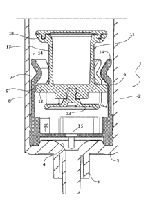
- figures 5 and 6 show, in axial section, a
variant of the foot valve according to the invention
respectively in closing position and in opening
position.
Detailed description of the invention
Initially referring to figure 1, a drip chamber
for medical infusion or transfusion apparatuses, formed
by a hollow elongated cylindrical body made of plastic
material having a radially elastically deformable
lateral wall 2 and a bottom wall 3 provided with an
outlet opening 4 communicating with a tubular connector
5 for connecting the drip chamber to a flexible pipe,
is indicated with 1.
The end of the drip chamber 1 opposite to the
bottom wall 3, indicated with 6, is designed to
sealingly receive a piercing element of the known type,
not represented.
Arranged inside the drip chamber 1 is a foot

CA 03012084 2018-07-20
WO 2017/134564
PCT/1B2017/050525
- 4 -
valve, generally indicated with 7, having the function
of controlling the flow through the outlet opening 4:
such passage should be open in presence of liquid
inside the drip chamber 1, and it should automatically
close should the liquid finish.
According to the invention, the foot valve 7
comprises a containment cage bush 8, formed by a crown
of elastically deformable axial sectors 9 projecting
from a flat base 10 sealingly fixed between the lateral
wall 2 and the bottom wall 3 of the drip chamber 1 and
forming an annular valve seat 15.
A float obturator 11, formed by a hollow body,
made of two pieces as illustrated or a single piece,
having a lower wall 12 and a shaped lateral wall 16,
floats inside the cage bush 8 in a guided fashion.
A disk-like membrane 13 made of soft material,
axially facing the annular valve seat 15 of the
containment cage bush 8 is fixed outside the lower wall
12.
The lateral wall 16 of the float obturator 11 has
an annular surface diverging towards the end 6 of the
drip chamber 1, which is arranged facing
correspondingly divergent portions 14 of the deformable
axial sectors 9 of the containment cage bush 8.
In the position for closing the foot valve 7,
represented in figure 2, the disk-like membrane 13 of
the float obturator 11 rests against the flat base 10
of the containment cage bush 8, so as to close the
annular valve seat 15 and thus the outlet opening 4 of
the drip chamber 1. This condition corresponds to the
absence of liquid in the drip chamber 1.
In presence of liquid, the foot valve 7 takes the
opening position represented in figures 1 and 3: the
float obturator 11 is displaced in the containment cage
bush 8 in a position such that the disk-like membrane

-5-
13 is separated from the annular valve seat 15, so as
to keep the passage open through the outlet opening 4
of the drip chamber 1.
The opening and closing displacements of the float
obturator 11 are efficiently guided by the containment
cage bush 8. In addition, the displacement thereof from
the closing position to the opening position can be
carried out in a comfortable and easy manner even
manually, by simply applying a radial deformation to
the elastically deformable lateral wall 2 of the drip
chamber 1 - using two fingers - so as to
correspondingly radially deform the deformable axial
sectors 9 of the containment cage bush 7 and transmit
an axial thrust of the float obturator 11 in the
direction of the end 6 of the drip chamber 1, due to
the interaction between the free and diverging ends 14
and the diverging annular surface 16.
In the light of the description above, it is clear
that the displacements of the float obturator 11
corresponding to the closing and opening of the foot
valve 7 occur not only in an efficiently guided manner
by the containment cage bush 8, but also for limited
axial travels that contribute to ensuring a perfect
closure and instantaneous re-opening of the foot valve
7.
Figures 5 and 6 show a variant of the foot valve
according to the invention, respectively represented in
the opening position and in the closing position.
In such variant, currently considered the
preferred embodiment, parts identical or similar to
previously described ones are indicated using the same
reference numbers. Its difference with respect to the
previous embodiments lies in that the flat base 10 of
the cage bush 8 is made in a single piece with the
deformable axial sectors 9 thereof. The obturator 11
8171151
Date Recue/Date Received 2023-02-03

- 6 -
has a cylindrical wall 17 whose upper end, indicated
with 18, is substantially radially turned towards the
external and it has a rounded surface to cooperate with
the diverging portions 14 of the deformable axial
sectors 9 of the containment cage bush 8, in a manner
similar to the previously described one.
Obviously, the construction details and the
embodiments may widely vary with respect to what has
been described and illustrated, without departing from
the scope of protection of the present invention as
defined in the claims that follow.
8171151
Date Recue/Date Received 2023-02-03

Representative Drawing
A single figure which represents the drawing illustrating the invention.
Administrative Status

For a clearer understanding of the status of the application/patent presented on this page, the site Disclaimer , as well as the definitions for Patent , Administrative Status , Maintenance Fee  and Payment History  should be consulted.

Administrative Status

Title Date
Forecasted Issue Date 2023-08-29
(86) PCT Filing Date 2017-02-01
(87) PCT Publication Date 2017-08-10
(85) National Entry 2018-07-20
Examination Requested 2021-11-12
(45) Issued 2023-08-29

Abandonment History

There is no abandonment history.

Maintenance Fee

Last Payment of $277.00 was received on 2024-01-22


 Upcoming maintenance fee amounts

Description Date Amount
Next Payment if standard fee 2025-02-03 $277.00
Next Payment if small entity fee 2025-02-03 $100.00

Note : If the full payment has not been received on or before the date indicated, a further fee may be required which may be one of the following

  • the reinstatement fee;
  • the late payment fee; or
  • additional fee to reverse deemed expiry.

Patent fees are adjusted on the 1st of January every year. The amounts above are the current amounts if received by December 31 of the current year.
Please refer to the CIPO Patent Fees web page to see all current fee amounts.

Payment History

Fee Type Anniversary Year Due Date Amount Paid Paid Date
Application Fee $400.00 2018-07-20
Maintenance Fee - Application - New Act 2 2019-02-01 $100.00 2019-01-18
Maintenance Fee - Application - New Act 3 2020-02-03 $100.00 2020-01-13
Maintenance Fee - Application - New Act 4 2021-02-01 $100.00 2021-01-20
Request for Examination 2022-02-01 $816.00 2021-11-12
Maintenance Fee - Application - New Act 5 2022-02-01 $203.59 2022-01-11
Maintenance Fee - Application - New Act 6 2023-02-01 $210.51 2023-01-19
Final Fee $306.00 2023-06-21
Maintenance Fee - Patent - New Act 7 2024-02-01 $277.00 2024-01-22
Owners on Record

Note: Records showing the ownership history in alphabetical order.

Current Owners on Record
INDUSTRIE BORLA S.P.A.
Past Owners on Record
None
Past Owners that do not appear in the "Owners on Record" listing will appear in other documentation within the application.
Documents

To view selected files, please enter reCAPTCHA code :


To view images, click a link in the Document Description column. To download the documents, select one or more checkboxes in the first column and then click the "Download Selected in PDF format (Zip Archive)" or the "Download Selected as Single PDF" button.

List of published and non-published patent-specific documents on the CPD .

If you have any difficulty accessing content, you can call the Client Service Centre at 1-866-997-1936 or send them an e-mail at CIPO Client Service Centre.


Document
Description 
Date
(yyyy-mm-dd) 
Number of pages   Size of Image (KB) 
Maintenance Fee Payment 2020-01-13 1 33
Request for Examination 2021-11-12 5 142
Examiner Requisition 2023-01-10 5 326
Amendment 2023-02-03 17 589
Description 2023-02-03 6 342
Claims 2023-02-03 2 112
Abstract 2018-07-20 2 77
Claims 2018-07-20 2 73
Drawings 2018-07-20 6 323
Description 2018-07-20 6 209
Representative Drawing 2018-07-20 1 66
Patent Cooperation Treaty (PCT) 2018-07-20 1 40
International Search Report 2018-07-20 3 96
National Entry Request 2018-07-20 5 129
Cover Page 2018-08-02 2 56
Maintenance Fee Payment 2019-01-18 1 33
Final Fee 2023-06-21 5 143
Representative Drawing 2023-08-14 1 22
Cover Page 2023-08-14 1 57
Electronic Grant Certificate 2023-08-29 1 2,527